-
Curtain end zones are automatically created at both ends of the curtains with H w / l w > 2.0 .
-
The critical wall height from the top of the foundation or the level where the length of the curtain in the plan is reduced by more than 20% , is automatically determined to provide the unfavorable conditions given in Equation (7.15) , not exceeding the value of 2l w .
-
Conditions given in 7.6.2.3 and 7.6.2.4 are automatically applied in determining the length of wall end zones in the plan .
ICONS
H cr = Curtain critical height
H w = Total curtain height measured from the top of the foundation or the ground floor slab
l w = Length of the curtain or tie-beam curtain piece in plan
Wall End Zones and Critical Wall Height Conditions
According to the Article 7.6.2.2 of TBDY , the critical wall height, H cr , is determined to meet the condition given in Equation 7.15 . Equation 7.15 according critical wall height 2l w at least to exceed, l w and H w / 6 values are determined such that the larger ones.

In this relation, H w is the wall height measured from the top of the foundation or the level at which the gross section bending stiffness of the wall is halved. In buildings where the stiffness of the basement floors are very large compared to the upper floors, and where the basement floor floors operate as a rigid diaphragm in the horizontal plane, the sizes of H w and H cr are taken into consideration from the ground floor floor upwards. In such buildings, the critical curtain zone is further extended downward at least along the height of the first basement floor below the ground floor.
In accordance with Article 7.6.2.1 of TBDY , wall end zones are formed at both ends of the walls in the plan with H w / l w > 2.0 ( Figure 7.11 ). Curtain end zones can be formed within their own thickness or at intersections of curtains.
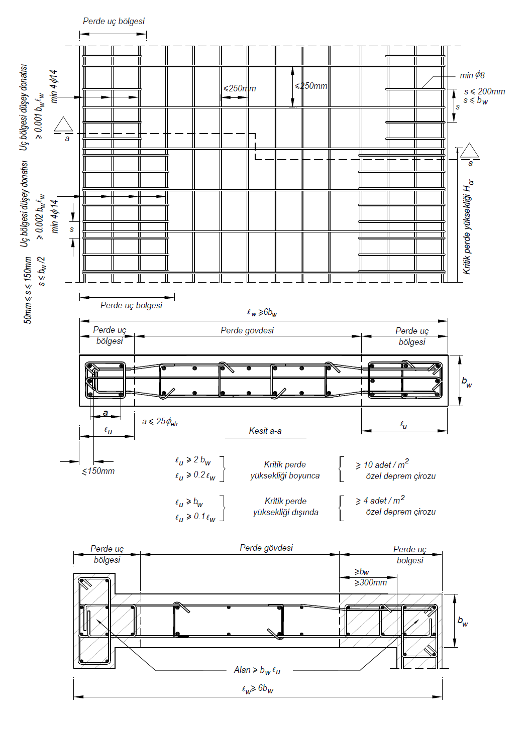
According to TBDY Article 7.6.2.3 , in rectangular walls;
-
The plan length of each of the wall end zones along the critical wall height is arranged so that it is not less than 20% of the total plan length of the curtain and twice the wall thickness.
-
For walls that are above the critical wall height, the plan length of each of the wall end zones is arranged such that the length in the plan is not less than 10% of the total length of the curtain and the wall thickness.
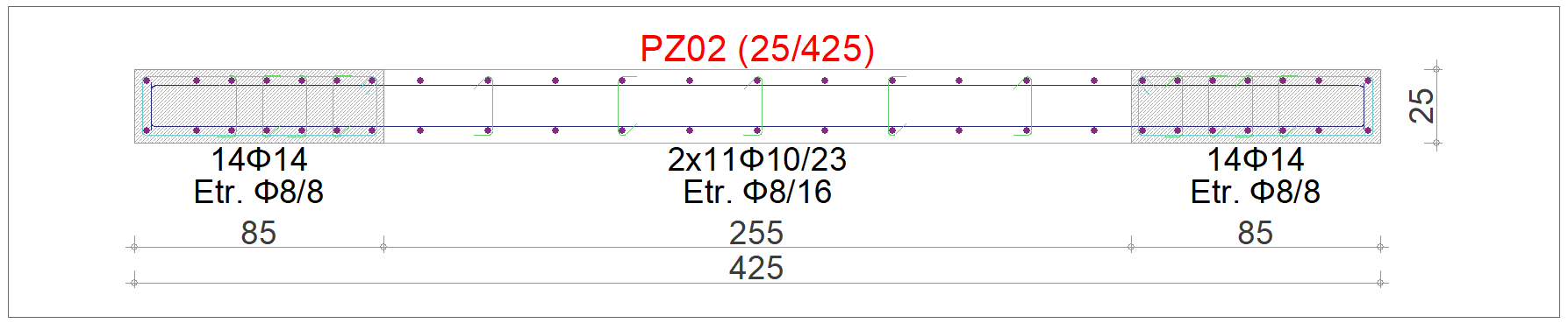
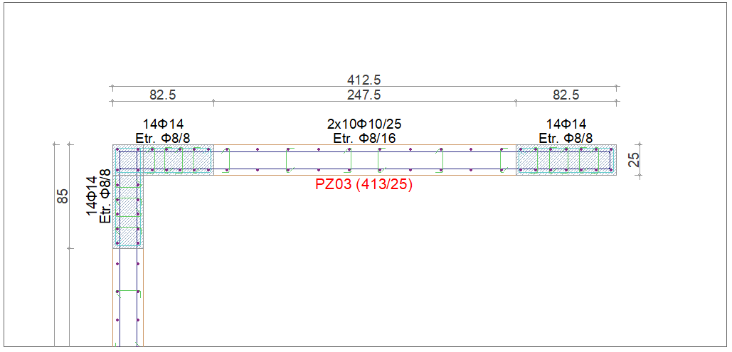
An example shape of the wall end zones formed within the wall thickness along the Critical Wall Height for a single wall is shown in the picture below. As can be seen, the length of the curtain in plan is 425 cm and its thickness is 25 cm. In this case, according to 7.6.2.3 , 20% of the total length in the plan (425 * 0.2 = 85 cm) and twice the thickness of the curtain (25 * 2 = 50 cm) are arranged so that they are not less than the values.
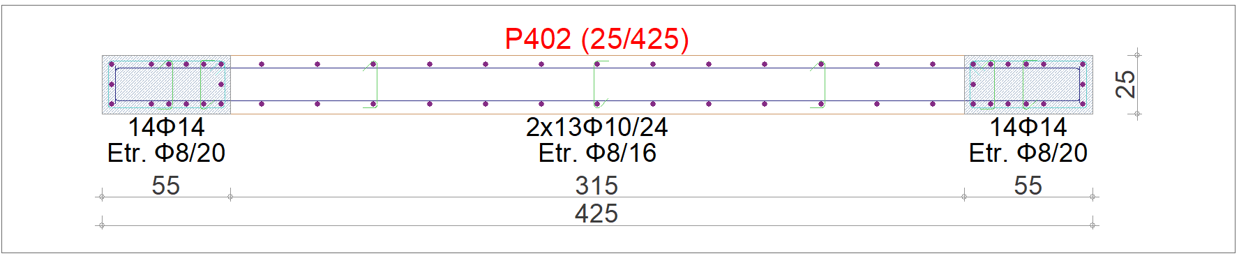
An example shape of the curtain end zones created in the walls above the critical wall height for a single curtain is shown in the picture below.
According to Article 7.6.2.4 of TBDY , for two intersecting walls , in the wall end regions;
-
Each curtain end zone is extended into the curtain body by at least the thickness of the curtain, not less than 300 mm.
-
The cross-sectional area of the wall end zone is arranged such that it is not less than the area defined in 7.6.2.3 for walls with rectangular cross-section .
An example of the curtain end zone formed at the end of a curtain that joins another curtain is shown in the picture below.
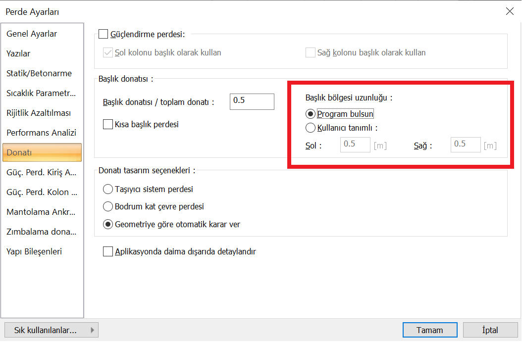
Curtain end zones are automatically determined by the program or can be entered as user defined. In the "Reinforcement" tab of the Curtain Settings window, the header zone length options are outlined in red in the picture below.
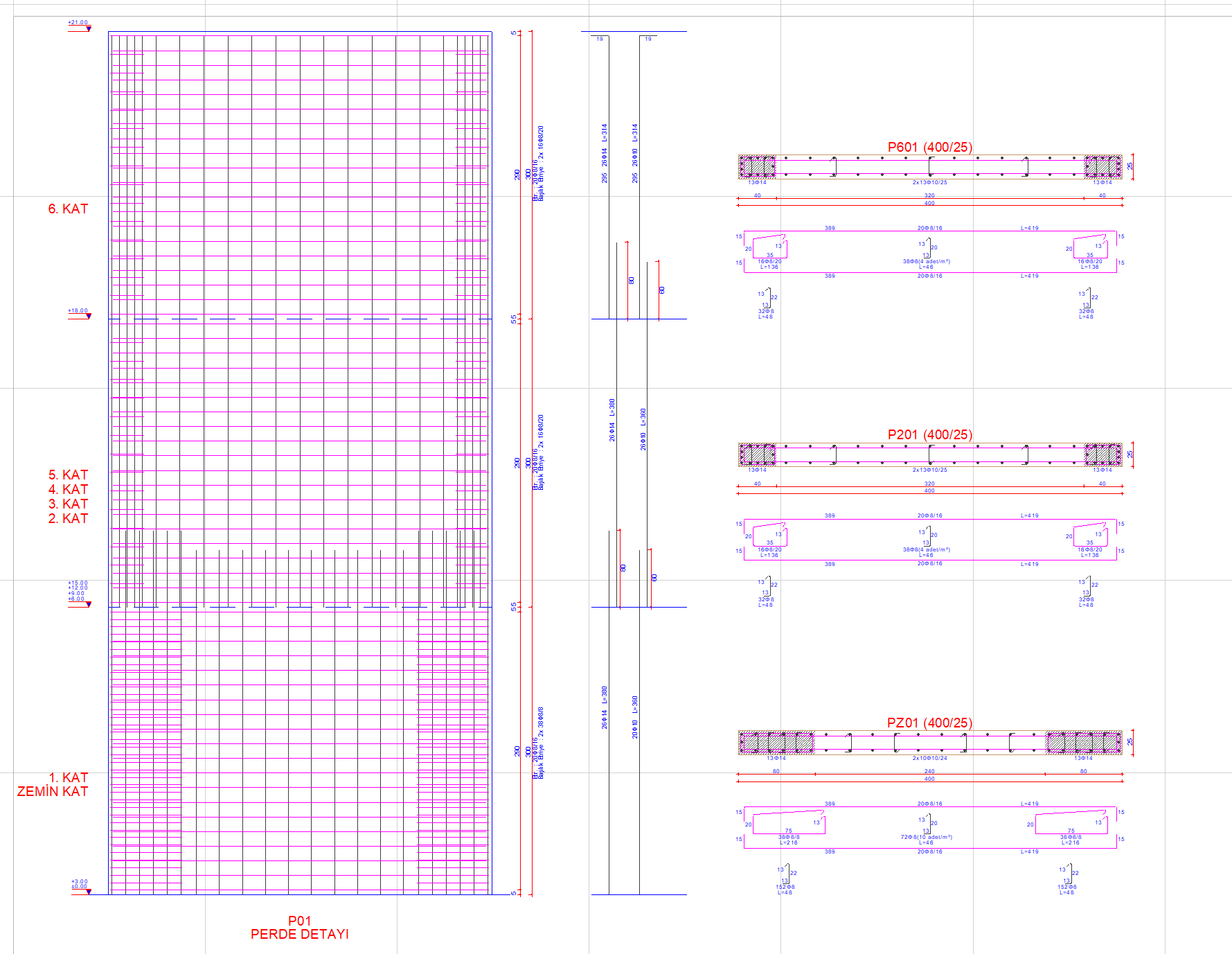
Using the curtain details command, the critical wall height and the wall end regions along the regions above this height can be seen.