
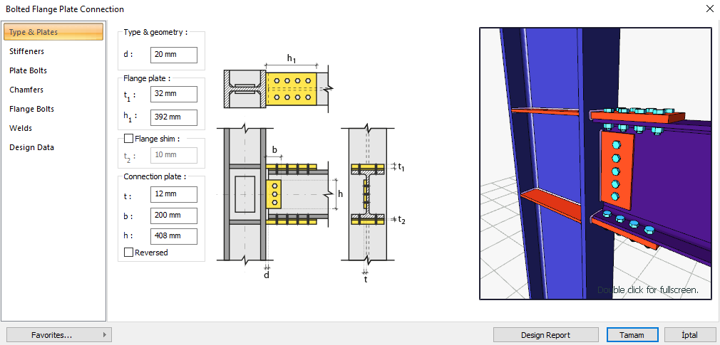
Bolted Flange Plate Connection is formed with header plates welded to the column head and bolted to the beam head. Bolt control, weld control, plate control and joint application limits control are performed automatically according to the placement of the elements of the joint. Head Plate Bolt Joint design is made automatically according to the Design, Calculation and Construction Principles of Steel Structures (ÇYTHYEDY) or AISC 360-16 regulations and a joint report is created. Joint detail application limits are checked according to TBDY Table 9B.2.
In the calculation of Head Plate Bolt Joint, horizontal and vertical bolt distances, butt plate weld thickness, continuity plate weld thickness and application limits are checked under geometry control. Bolt diameter in strength control, slip in cap and body bolts, crush in cap and body bolt hole, crush in beam cap bolt hole, head plate tensile yield and tensile failure, block slip in head plate and beam head, beam and body plate shear failure, block in body plate slip, body plate bending yield, slip plate column head weld strength, column panel region slip and slip region thickness control are performed.
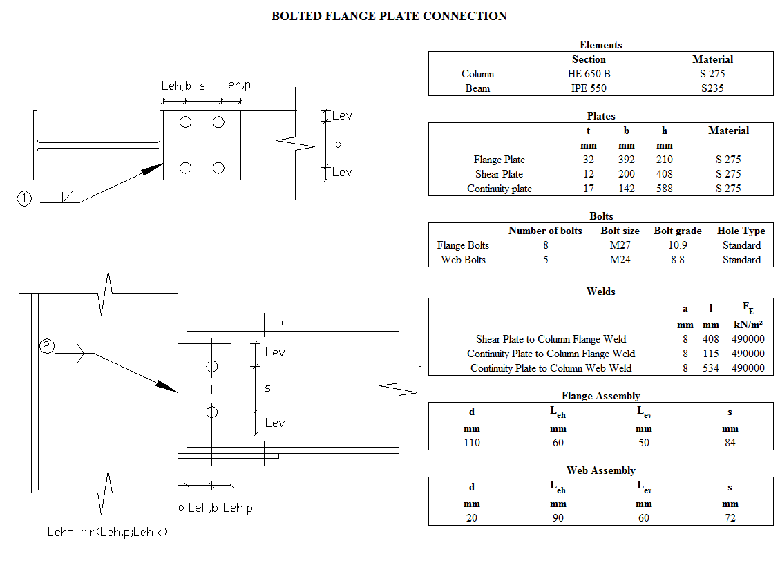
Connection Geometry
Geometry Checks
Bolt Spacing at Flange
|
|
ÇYTHYEDY 13.3.6 |
|
|
|
|
84 mm |
|
|
|
|
27 mm |
s =84 mm > smin = 3*27=81 mm |
√ |
Horizontal Edge Distance at Flange
|
|
ÇYTHYEDY 13.3.7 |
|
|
|
|
60 mm |
L e ≥ 2d = 2 * 27 = 54 mm conformity check for application |
√ |
|
|
36 mm |
Minimum distance check according to Table 13.9 |
√ |
Vertical Edge Distance at Flange
|
|
ÇYTHYEDY 13.3.7 |
|
|
|
|
50 mm |
Check suitability for L e ≥ 2d = 2 * 27 = mm application |
√ |
|
|
36 mm |
Minimum distance check according to Table 13.9 |
√ |
Weld Thickness
|
|
ÇYTHYEDY 13.3.7 |
|
|
|
|
9 mm |
|
√ |
|
|
3.5 mm |
Table 13.4 |
√ |
Bolt Spacing at Web
|
|
ÇYTHYEDY 13.3.6 |
|
|
|
|
72 mm |
|
|
|
|
24 mm |
s =7 mm > smin = 3*24=72 mm |
√ |
Horizontal Edge Distance at Web
|
|
ÇYTHYEDY 13.3.7 |
|
|
|
|
90 mm |
Conformity check for L e ≥ 2d = 2 * 24 = 48 mm application |
√ |
|
|
32 mm |
Minimum distance check according to Table 13.9 |
√ |
Vertical Edge Distance at Web
|
|
ÇYTHYEDY 13.3.7 |
|
|
|
|
60 mm |
L eh ≥ 2d = 2 * 24 = 48 mm conformity check for application |
√ |
|
|
32 mm |
Minimum distance check according to Table 13.9 |
√ |
Shear Plate to Column Flange Weld Size
|
a ≥ a min |
ÇYTHYEDY 13.3.7 |
|
|
|
a |
8 mm |
|
√ |
|
a min |
3.5 mm |
Table 13.4 |
√ |
Continuity Plate to Column Flange Weld Size
|
|
ÇYTHYEDY 13.3.7 |
|
|
|
|
8 mm |
|
√ |
|
|
4 mm |
Table 13.4 |
√ |
Continuity Plate to Column Web Weld Size
|
|
ÇYTHYEDY 13.3.7 |
|
|
|
|
8 mm |
|
√ |
|
|
4 mm |
Table 13.4 |
√ |
Connection Detail Prequalification Limits (TBDY Table 9B.2)
|
Beam span / Beam cross-section height |
9144 mm /550 mm=16.63 |
≥9.0 |
|
Beam cross-section height, d b |
550 mm |
≤ 920 |
|
Beam head thickness, t bf |
17.2 mm |
≤25 |
|
Column cross section height |
650 mm |
≤ 920 mm |
|
Bolt class |
8.8 |
8.8 - 10.9 |
|
Bolt size |
M27 |
≤ M27 |
|
Min yield stress of header plate material |
275 MPa |
235 /275 / 355 MPa |
|
Title plate welding |
CJP |
CJP |
Strength Checks
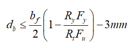
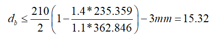
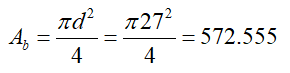
Bolt diameter
|
|
210 mm |
Table 9B.3 |
|
|
1.40 |
|
|
|
235.359 N/mm2 |
|
|
|
1.10 |
|
|
|
362.846 N/mm2 |
|
|
|
|
|
|
|
|
|
|
Required |
Available |
Ratio |
Control |
|---|---|---|---|
|
15.32 mm |
27 mm |
0.567 |
√ |
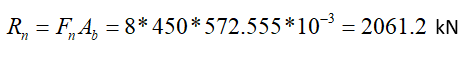
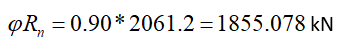
Bolt Shear at Flange
|
|
|
|
|
|
|
|
|
|
|
|
|
Required |
Available |
Ratio |
Control |
|---|---|---|---|
|
1628.396 kN |
1855.079 kN |
0.878 |
√ |
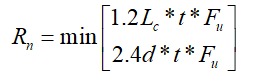
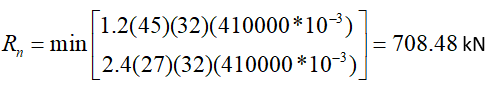
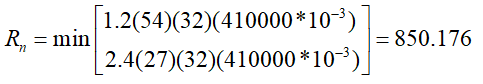
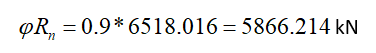
Bolt Bearing on Flange Plate
|
|
27+3=30 mm |
|
|
|
|
|
|
|
|
ÇYTHYEDY 13.3.13 Equation 13.14a and13.14b |
|
|
|
|
|
|
|
|
|
|
|
|
|
|

|
|
|
|
|
|
|
Required |
Available |
Ratio |
Control |
|---|---|---|---|
|
1628.396 kN |
5866.214 kN |
0.278 |
√ |
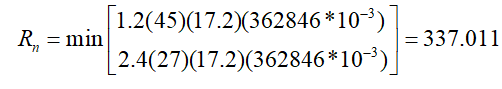
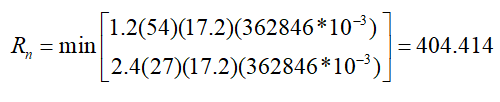
Bolt Bearing on Beam Flange
|
|
27+3=30 mm |
|
|
|
|
|
|
|
|
ÇYTHYEDY 13.3.13 Equation 13.14a and13.14b |
|
|
|
|
|
|
|
|
|
|
|
|
|
|

|
|
|
|
|
|
|
Required |
Available |
Ratio |
Control |
|---|---|---|---|
|
1628.396 kN |
279,455 kN |
0.584 |
√ |
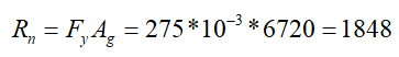
Flange Plate Tension Yield
|
|
|
|
|
|
275 N/mm2 |
|
|
|
|
ÇYTHYEDY 13.15 |
|
|

|
|
|
Required |
Available |
Ratio |
Control |
|---|---|---|---|
|
1628.396 kN |
1848 kN |
0.881 |
√ |
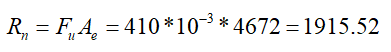
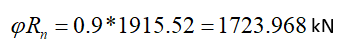
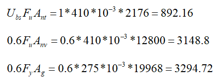
Flange Plate Tension Rupture
|
|
|
|
|
|
|
|
|
|
410 N/mm2 |
|
|
|
1.00 |
|
|
|
|
ÇYTHYEDY 13.16 |
|
|
|
|
|
Required |
Available |
Ratio |
Control |
|---|---|---|---|
|
1628.396 kN |
1723.968 kN |
0.945 |
√ |
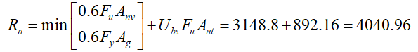
Flange Plate Block Shear
|
|
|
|
|
|
|
|
|
|
|
|
|
|
275 N/mm2 |
|
|
|
410 N/mm2 |
|
|
|
1 |
|
|
|
|
|
|
|
|
ÇYTHYEDY 13.19 |
|
|
|
|
|
Required |
Available |
Ratio |
Control |
|---|---|---|---|
|
1628.396 kN |
3636.864 kN |
0.448 |
√ |
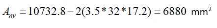
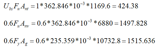
Beam Flange Block Shear
|
|
|
|
|
|
|
|
|
|
235.359 N/mm2 |
|
|
|
362.846 N/mm2 |
|
|
|
1 |
|
|
|
|
|
|
|

|
ÇYTHYEDY 13.19 |
|
|
|
|
|
Required |
Available |
Ratio |
Control |
|---|---|---|---|
|
1628.396 kN |
1729.992 kN |
0.941 |
√ |
Bolt Shear at Web
|
|
|
|
|
|
|
|
|
|
|
|
|
Required |
Available |
Ratio |
Control |
|---|---|---|---|
|
89.994 kN |
146,574 kN |
0.614 |
√ |
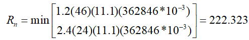
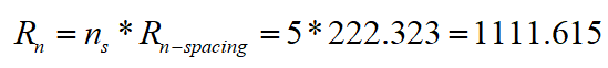
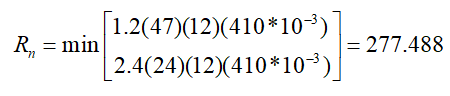
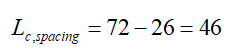
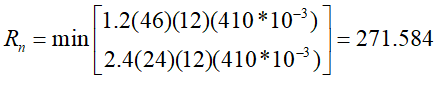
Bolt Bearing on Beam Web
|
|
24+2=26 mm |
|
|
|
|
ÇYTHYEDY 13.3.13 Equation 13.14a and13.14b |
|
|
|
|
|
Rn-spacing |
|
|
|
|
|
|
|
|
|
|
|
Required |
Available |
Ratio |
Control |
|---|---|---|---|
|
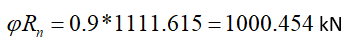
246.43 kN |
1000.454 kN |
0.246 |
√ |
Bolt Bearing on Web Plate
|
|
24+2=26 mm |
|
|
|
|
|
|
|
|
ÇYTHYEDY 13.3.13 Equation 13.14a and13.14b |
|
|
|
|
|
|
|
|
|
|
|
|
|
|

|
|
|
|
|
|
|
Required |
Available |
Ratio |
Control |
|---|---|---|---|
|
246.43 kN |
1227,442 kN |
0.201 |
√ |
Web Plate Shear Yield
|
|
|
|
|
|
275 N/mm2 |
|
|
|
|
ÇYTHYEDY 13.17 |
|
|
|
|
|
Required |
Available |
Ratio |
Control |
|---|---|---|---|
|
246.43 kN |
807.84 kN |
0.305 |
√ |
Web Plate Shear Rupture
|
|
|
|
|
|
410 N/mm2 |
|
|
|
|
ÇYTHYEDY 13.17 |
|
|
|
|
|
Required |
Available |
Rate |
Control |
|---|---|---|---|
|
246.43 kN |
712,022 kN |
0.346 |
√ |
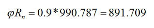
Beam Shear Rupture
|
|
|
|
|
|
410 N/mm2 |
|
|
|
|
ÇYTHYEDY 13.17 |
|
|
|
|
|
Required |
Available |
Ratio |
Control |
|---|---|---|---|
|
246.43 kN |
891.709 kN |
0.276 |
√ |
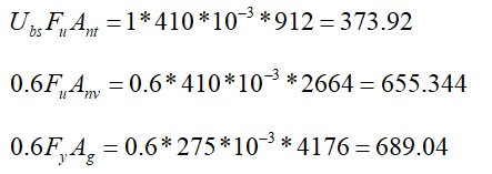
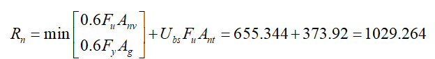
Web Plate Block Shear
|
|
|
|
|
|
|
|
|
|
|
|
|
|
275 N/mm2 |
|
|
|
410 N/mm2 |
|
|
|
1 |
|
|
|
|
|
|
|
|
ÇYTHYEDY 13.19 |
|
|
|
|
|
Required |
Available |
Ratio |
Control |
|---|---|---|---|
|
246.43 kN |
926,338 kN |
0.266 |
√ |
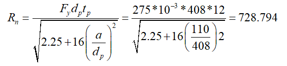
Web Plate Flexural Yield
|
|
408 mm |
|
|
|
275 N/mm2 |
|
|
|
12 mm |
|
|
|
110 mm |
|
|
|
|
|
|
|
|
|
|
Required |
Available |
Ratio |
Control |
|---|---|---|---|
|
246.43 kN |
728,794 kN |
0.338 |
√ |
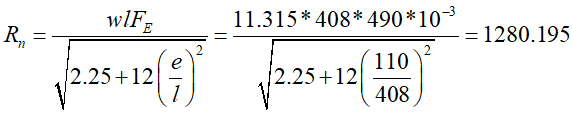
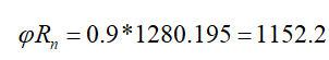
Shear Plate to Column Flange Weld Strength
|
in |
11.315 mm |
|
|
|
490 N/mm2 |
|
|
l |
408 mm |
|
|
is |
110 mm |
|
|
|
|
|
|
|
|
|
|
Required |
Available |
Ratio |
Control |
|---|---|---|---|
|
246.43 kN |
1152.2 kN |
0.214 |
√ |
Column Panel Zone Shear
|
|
429,124 kN |
ÇYTHYEDY 13.29a |
|
|
|
|
|
|
275000 kN/m2 |
|
|
|
28634.759 mm2 |
|
|
|
650 mm |
|
|
|
16 mm |
|
|
|
|
|
|
|
|
|
|
Required |
Available |
Ratio |
Control |
|---|---|---|---|
|
1379.649 kN |
1716 kN |
0.804 |
√ |
Panel Zone Thickness
|
t min ≥u / 180 |
|
TBDY 2018 9.3.4.2b |
|
tmin = tw |
16 mm |
|
|
|
16 mm |
|
|
u |
2207.2 mm |
|
|
Required |
Available |
Ratio |
Control |
|---|---|---|---|
|
12.262 mm |
16 mm |
0.766 |
√ |
Next Topic