
Moment and axial force diagrams of a system consisting of two rods according to 3 different states of freedom were compared with the manual results of ideCAD Structural.
Important Note: Given systems become isostatic with added freedoms, they are independent of element stiffness in terms of support reactions and internal force diagrams. For this reason, the results of the solutions below will not change in any material or section geometry selection.
|
Loading Status |
Controlled internal force |
ideCAD Static |
Manual solution |
Percentage of error |
|---|---|---|---|---|
|
|
N (chicken) |
0.00 |
0.00 |
0% |
|
M (kip-ft) |
-50.00 |
-50.00 |
0% |
|
|
|
N (chicken) |
0.00 |
0.00 |
0% |
|
M (kip-ft) |
-50.00 |
-50.00 |
0% |
|
|
|
N (chicken) |
-5.00 |
-5.00 |
0% |
|
M (kip-ft) |
0.00 |
0.00 |
0% |
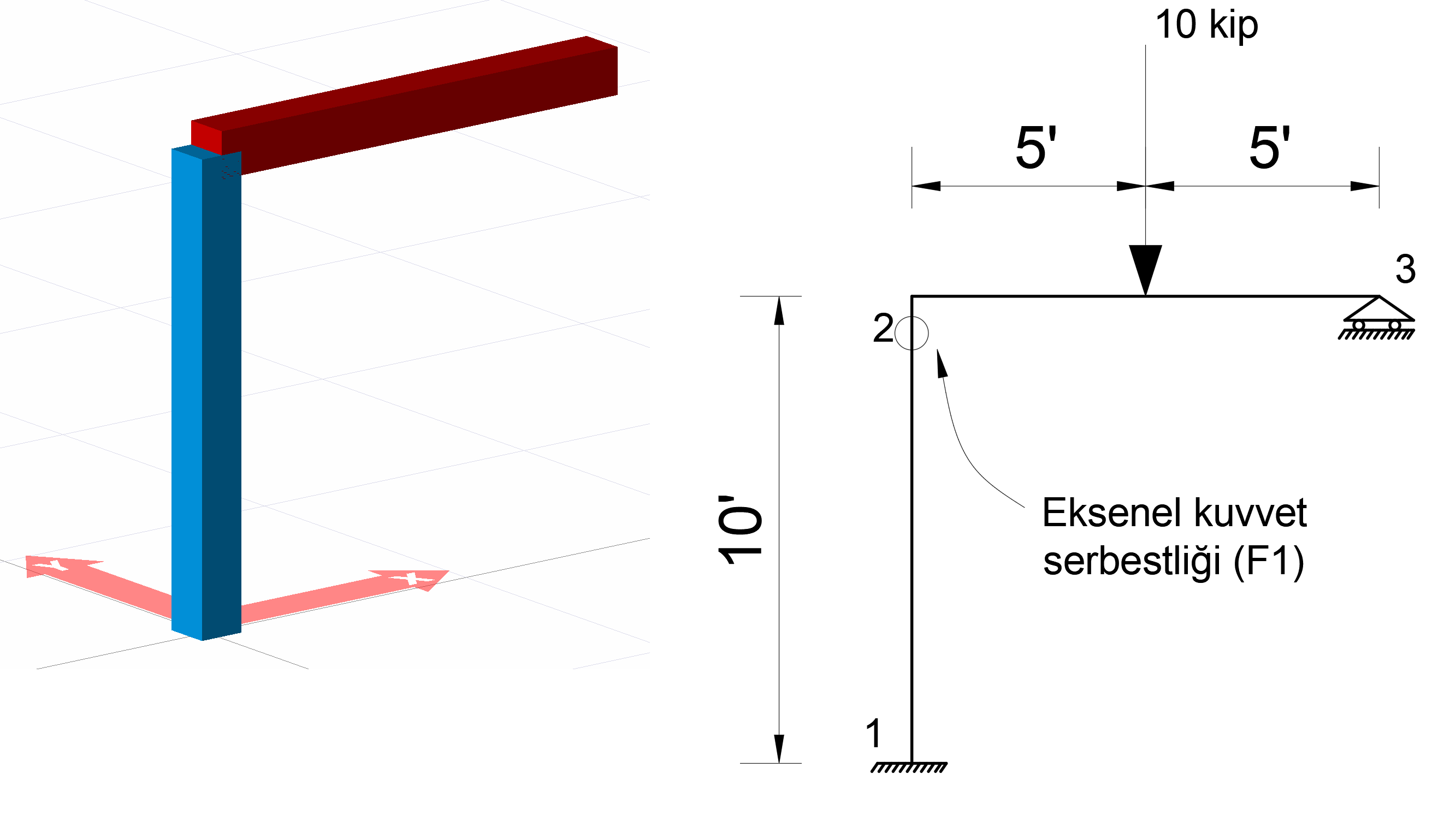
Geometric Properties and System Description
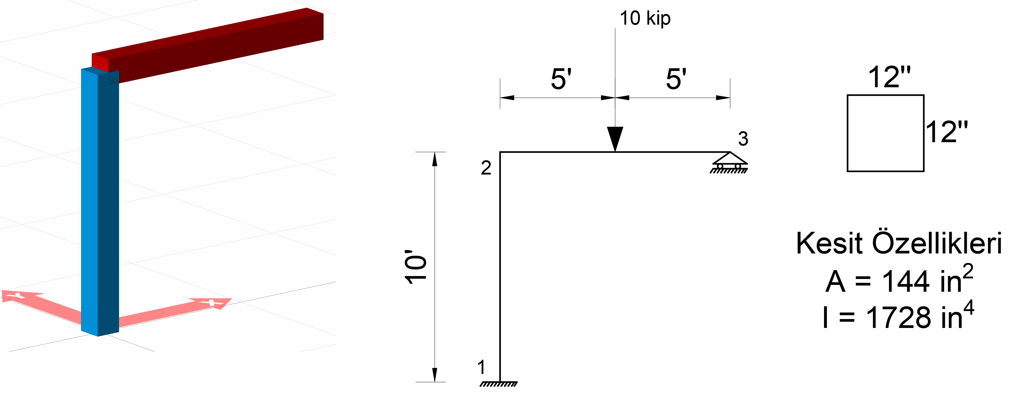
In the above system, a system consisting of 2 sticks and 3 nodes is given. The lengths of these rods are defined as 10 ft. Axial force cerebstence (F1) shall be defined on the end of the rod located at joint number 2 between joints 1-2, slip freedom (F2) and moment freedom (M3) shall be defined on the end of the rod located at joint point 2 between joints 2-3. In case these freedoms are defined, the system will become isostatic. In isostatic systems, internal force diagrams are independent from cross section geometry and material. Therefore, the internal force diagrams of the system will not change in case of a different material or section selection.
A square section with a side of 12 inches is used as a rod element.
The area of the square section is calculated as A = 12 * 12 = 144 in 2 and the
moment of inertia I = (1/12) * (12 * 12 3 ) = 1728 in 4
.
The modulus of elasticity of the material used is taken into consideration as E = 29000 k / in 2 .
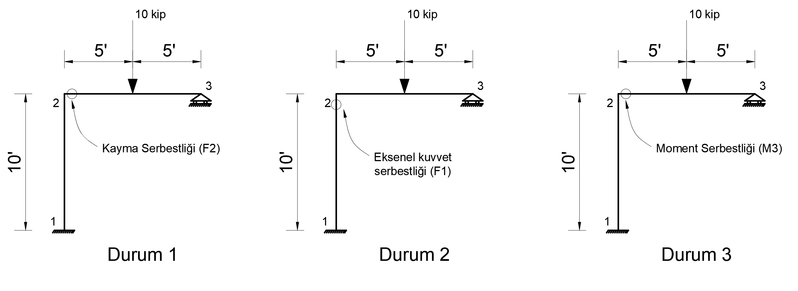
Loading Cases
In the above system, 3 support conditions are defined below. These conditions are named Case 1, Case 2 and Case 3. For Case 1, the freedom of sliding (F2) on the end of the rod located at joint 2 between joints 2-3 for Case 2, the axial force cerebstence (F1) to the end of the rod located at joint 1-2 between joint 1-2 for Case 2, and for Case 3 Moment freedom (M3) is defined at the end of the rod between the joints 2-3. A 10 kip single load was applied from the middle of the rod between 2-3 joints in all support conditions.
The following figure shows the systems for Case 1, Case 2, and Case 3.
You can find the files with defined loading status below.
Durum_1_Eleman_serbestlikleri.rarDurum_2_Eleman_serbestlikleri.rarDurum_3_Eleman_serbestlikleri.rar
Condition 1
For Case 1, the end of the rod located at joint 2 between the 2-3 joints has the freedom to slip (F2) and a 10 kip single load is applied to the rod between the 2-3 joints.
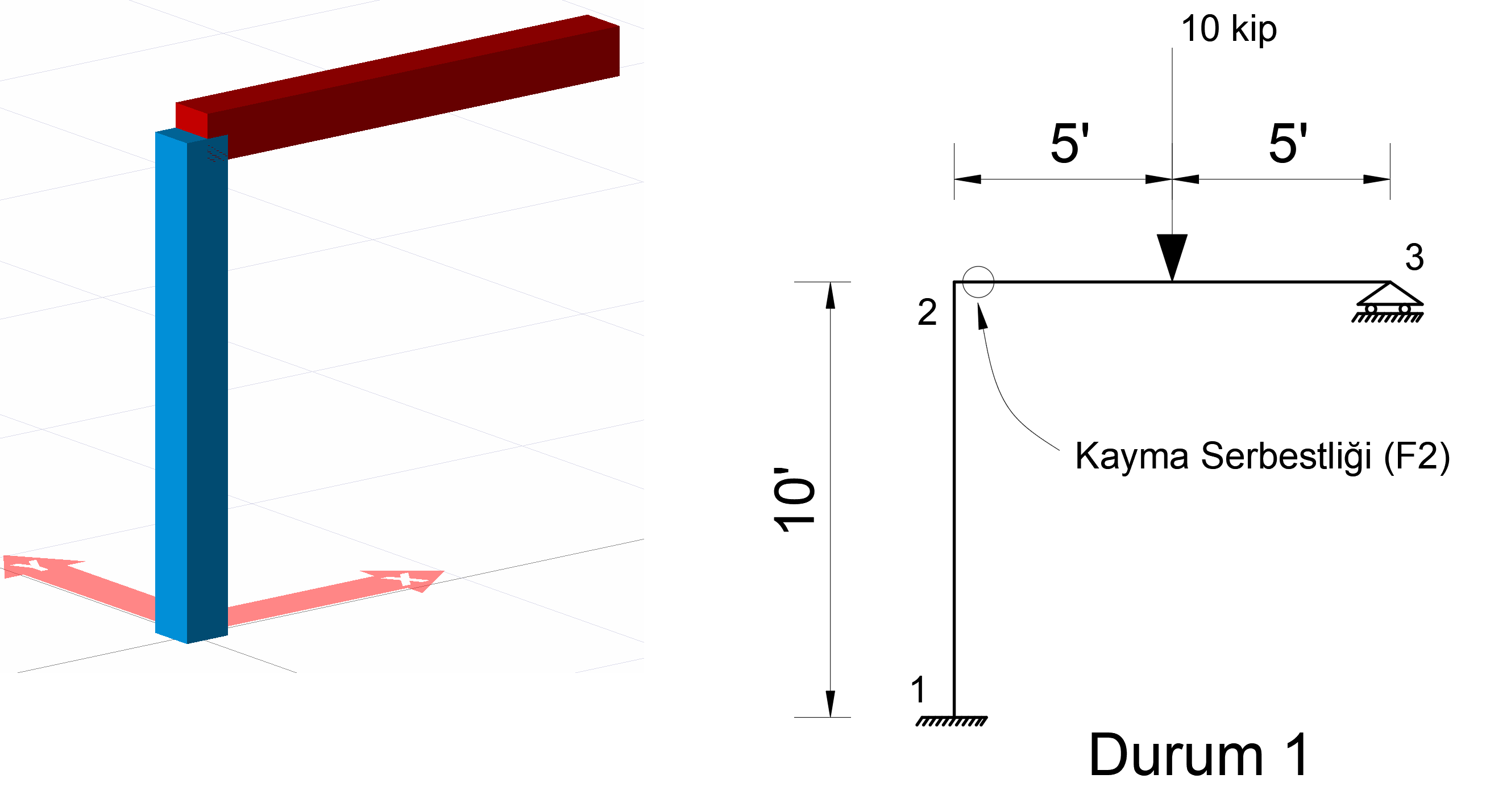
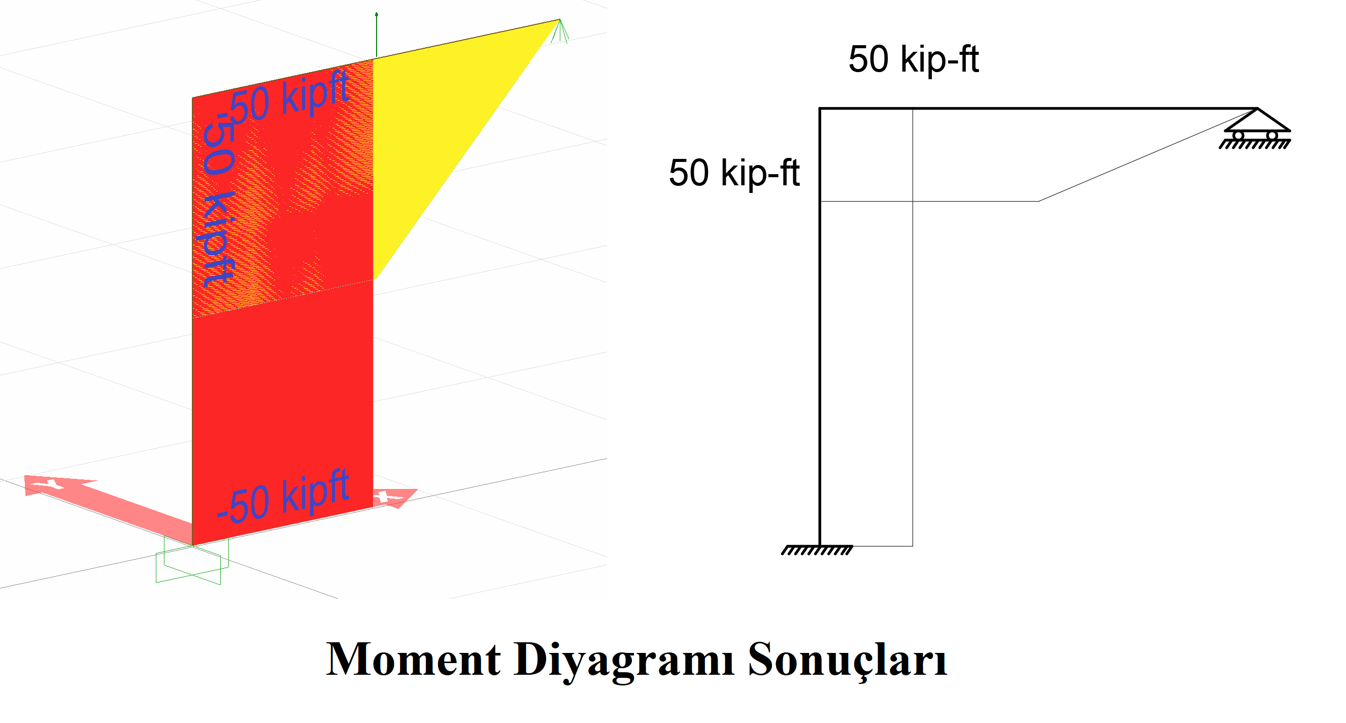
The support reactions, rod end forces, moment diagram and axial force diagram resulting from this loading are shown in the picture below.

Due to the freedom of F2, no axial force occurred in the column. The bending moment is the moment value of 10 * 5 = 50 kip-ft due to a 10 kip vertical load.
The manually calculated moment and axial force diagram gives exactly the same results with ideCAD Structural.
Condition 2
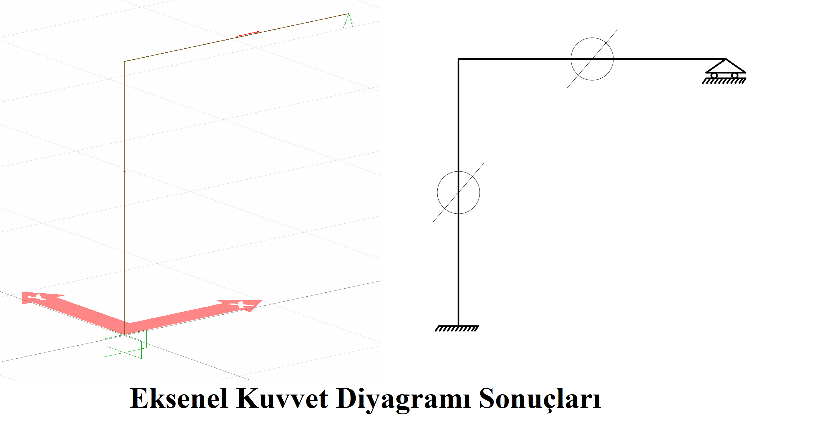
For Case 2, the axial force cerebrasy (F1) is defined at the end of the rod between joints 1-2 at joint 2, and a 10 kip single load is applied to the rod between the 2-3 joints.
The support reactions, rod end forces, moment diagram and axial force diagram resulting from this loading are shown in the picture below.
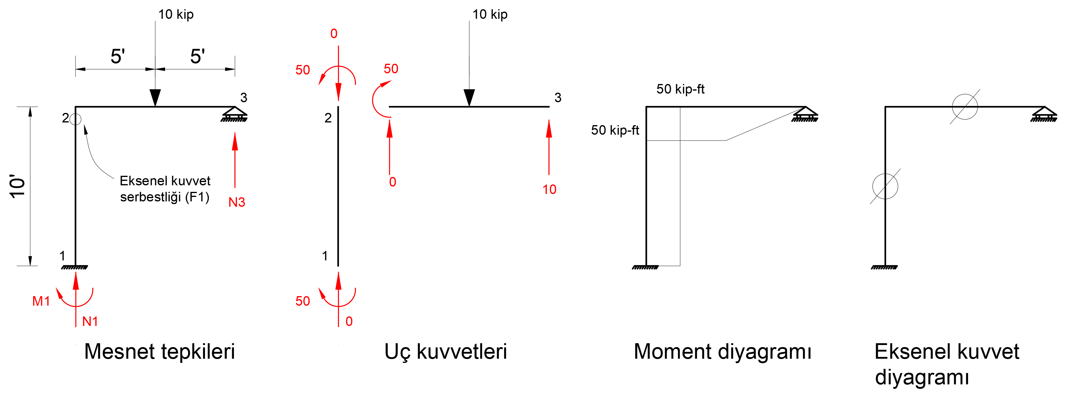
Due to the F1 freedom, no axial force occurred in the column. The bending moment is the moment value of 10 * 5 = 50 kip-ft due to a 10 kip vertical load.
The manually calculated moment and axial force diagram gives exactly the same results with ideCAD Structural.
Condition 3
For case 3, moment freedom (M3) is defined at the end of the rod at joint 2 between joints 2-3 and a 10 kip single load is applied to the rod between joints 2-3.
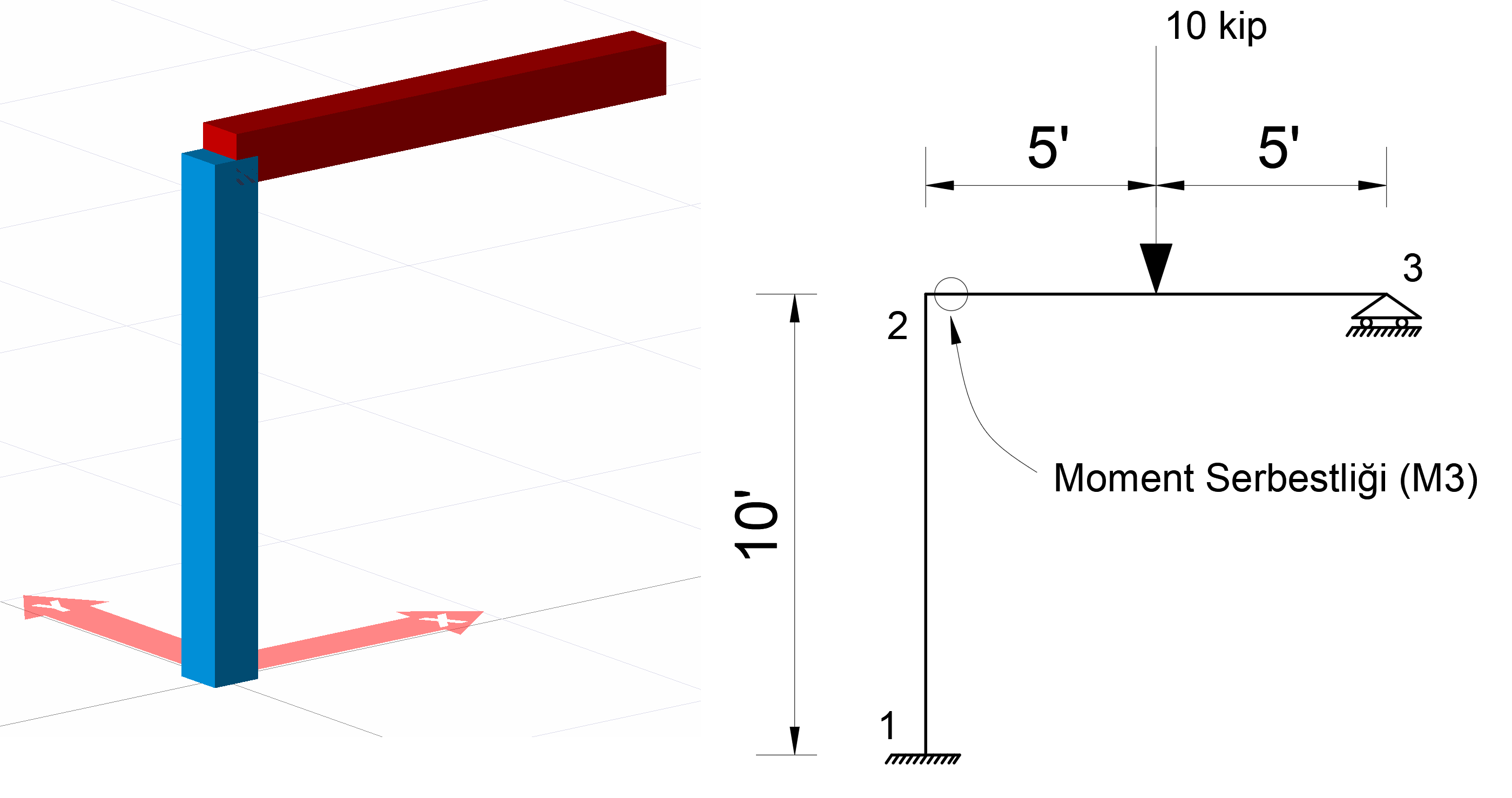
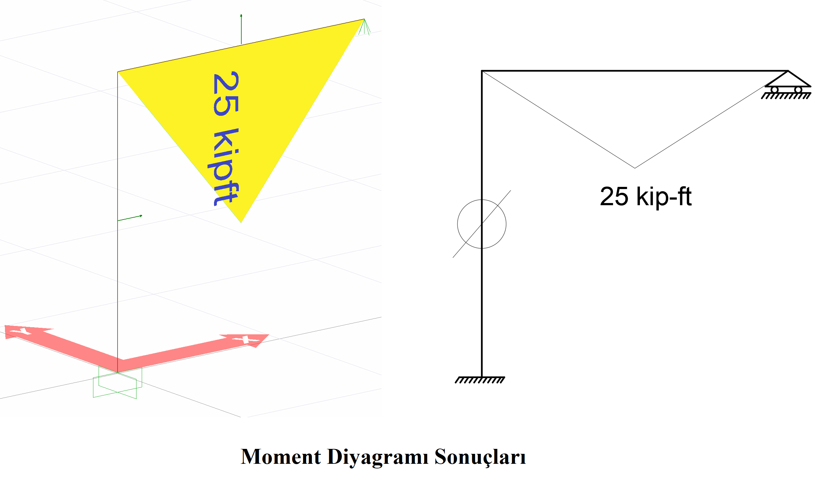
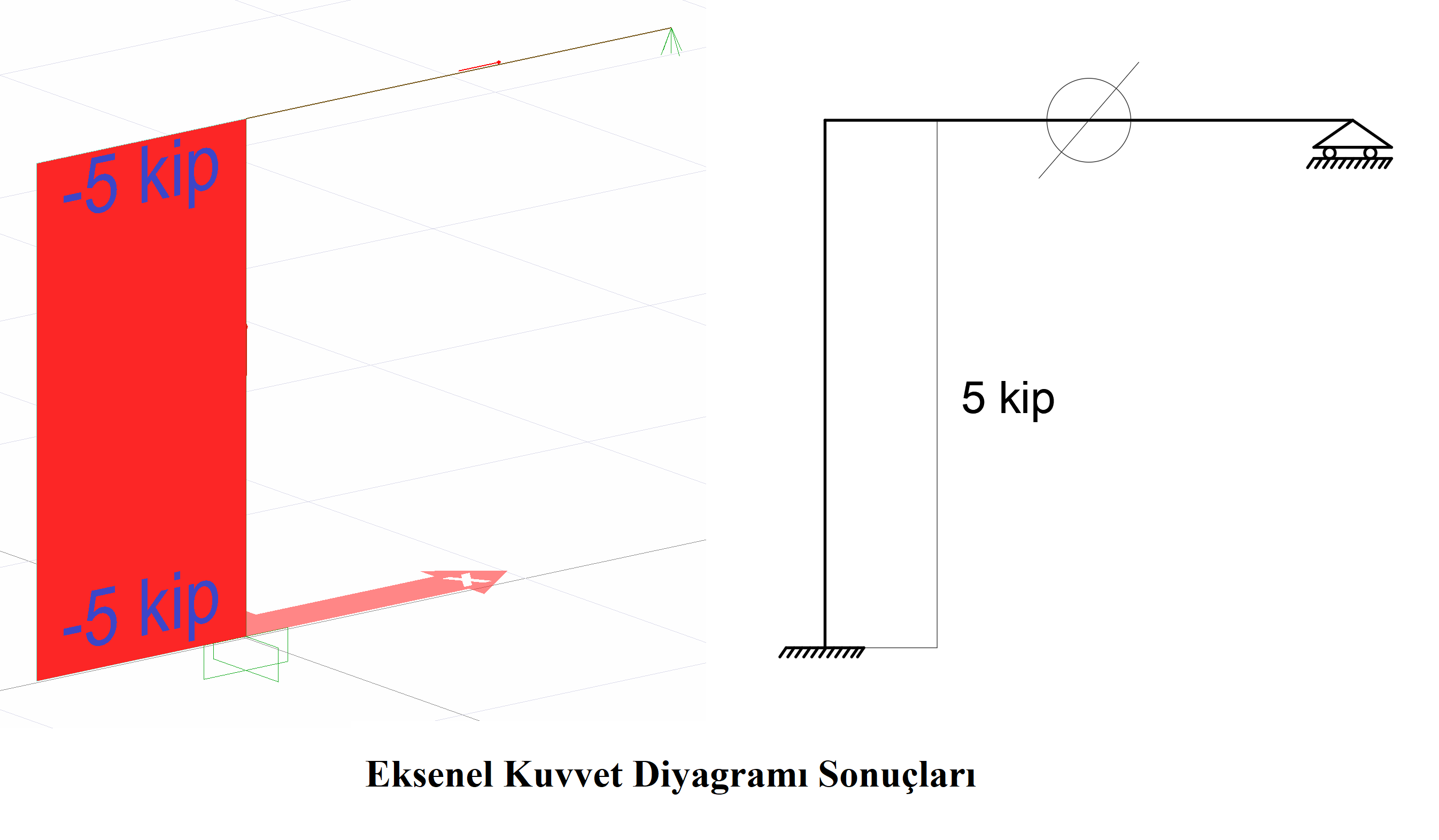
The support reactions, rod end forces, moment diagram and axial force diagram resulting from this loading are shown in the picture below.
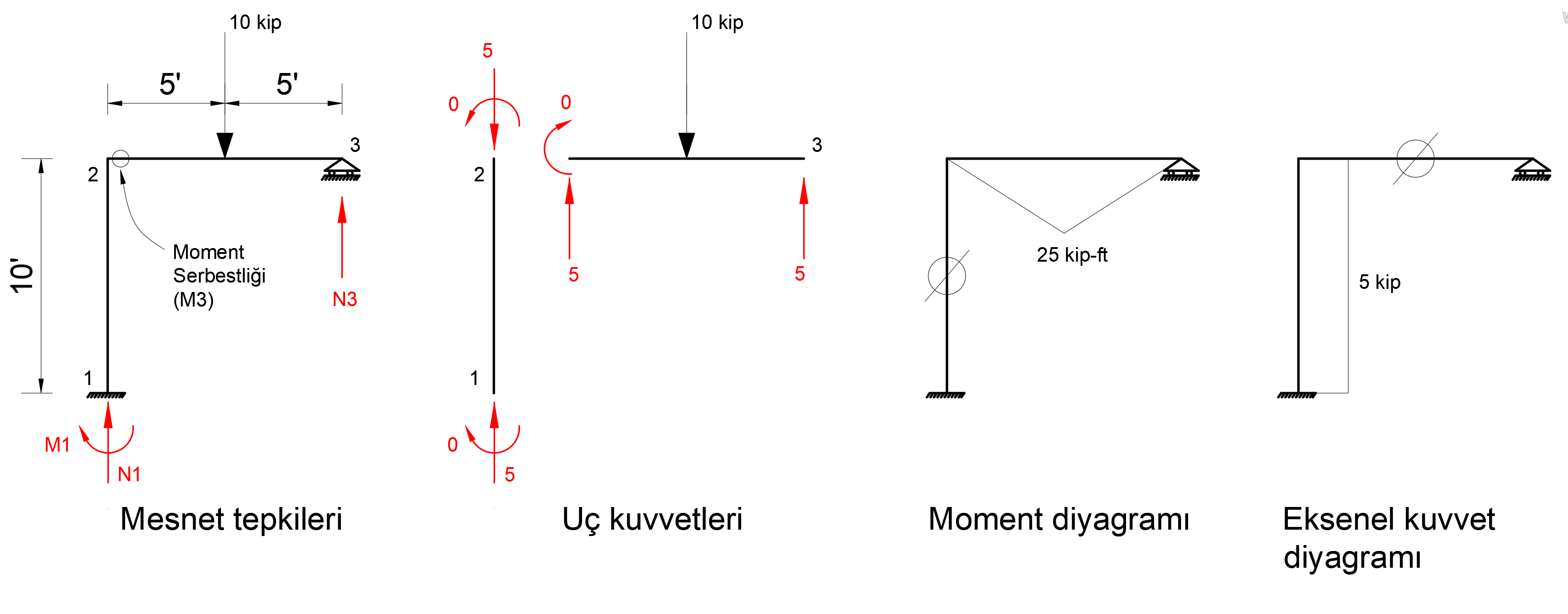
Due to M1 freedom, in the element (column) between 1-2 joints, no moment value has occurred, only an axial force of 5 kip has occurred. Moment freedom at the left end of the element between the 2-3 joints, and at the right end, no moment will occur at these ends from the movable support groove, a moment of 5 * 5 = 25 kip-ft will occur in the middle of the rod due to the singular load effect. In addition, due to the 10 kip vertical load, a 5 kip support reaction will occur on the supports 1 and 3, and a uniformly distributed 5 kip axial force will occur in the column.
The manually calculated moment and axial force diagram gives exactly the same results with ideCAD Structural.
Next Topic