
-
Along the critical wall height , the ratio of the total vertical reinforcement area in each of the wall end zones is at least 0.002, except for this height, this ratio is not less than 0.001.
-
The conditions that the longitudinal reinforcement amount should not be less than 4ϕ14 in each of the wall end zones and the minimum longitudinal reinforcement ratio should be 0.03 (0.06 in the overlap zone) at the wall end zones are automatically applied.
-
The diameter of the transverse reinforcement to be used in the end regions is not taken less than 8 mm. And the stirrup arms and / or horizontal spacing between crossties, a , greater than the diameter of hoops and crossties 25 of the solid is not selected.
-
7.6.2.2 as defined in the critical wall height of the wall end zones along, for winding zones of columns 7.3.4.1 from Eq. (7.1) "in the second condition of at least the determined transverse reinforcement 2/3 condition at user discretion.
-
In the vertical direction, the stirrup and / or tie-dye spacing is not taken larger than 150 mm and smaller than 50 mm. This gap should not be more than 6 times the longitudinal reinforcement diameter and 1/3 of the wall thickness.
-
The transverse reinforcements in the wall end zone are continued inside the foundation for a height not less than 300 mm and wall thickness.
-
The stirrups and / or trousers spacing in vertical direction in the wall end regions outside the critical wall height shall not be taken larger than the wall thickness and 200 mm.
ICONS
ϕ = Rebar diameter
Reinforcement Conditions in Wall End Regions
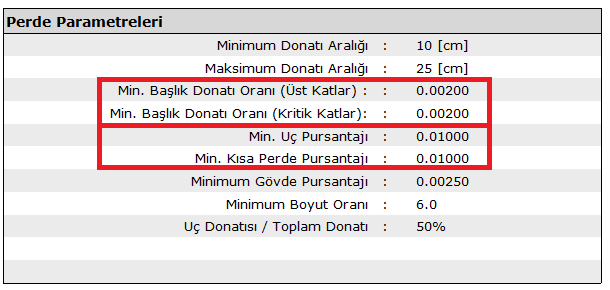
In the wall end zones, the ratio of the total vertical reinforcement area of each wall end zone along the critical wall height defined in 7.6.2.2 in accordance with Article 7.6.5.1 of TBDY is arranged to be at least 0.002. Except for the critical curtain height , this ratio is arranged to be not less than 0.001. The longitudinal reinforcement ratio in the wall end zones is arranged to be at most 0.03 (0.06 in the overlap zone). At the same time, the amount of longitudinal reinforcement in the wall end regions is arranged not to be less than 4ϕ14.
The following picture shows the Curtain Parameters table of the Curtain Preliminary Information report . In this report, minimum longitudinal reinforcement ratio values for wall end zone specified in 7.6.5.1 are shown.
Conditions mentioned in 7.6.5.1 at the wall end zones are given in Figure 7.11 TBDY .
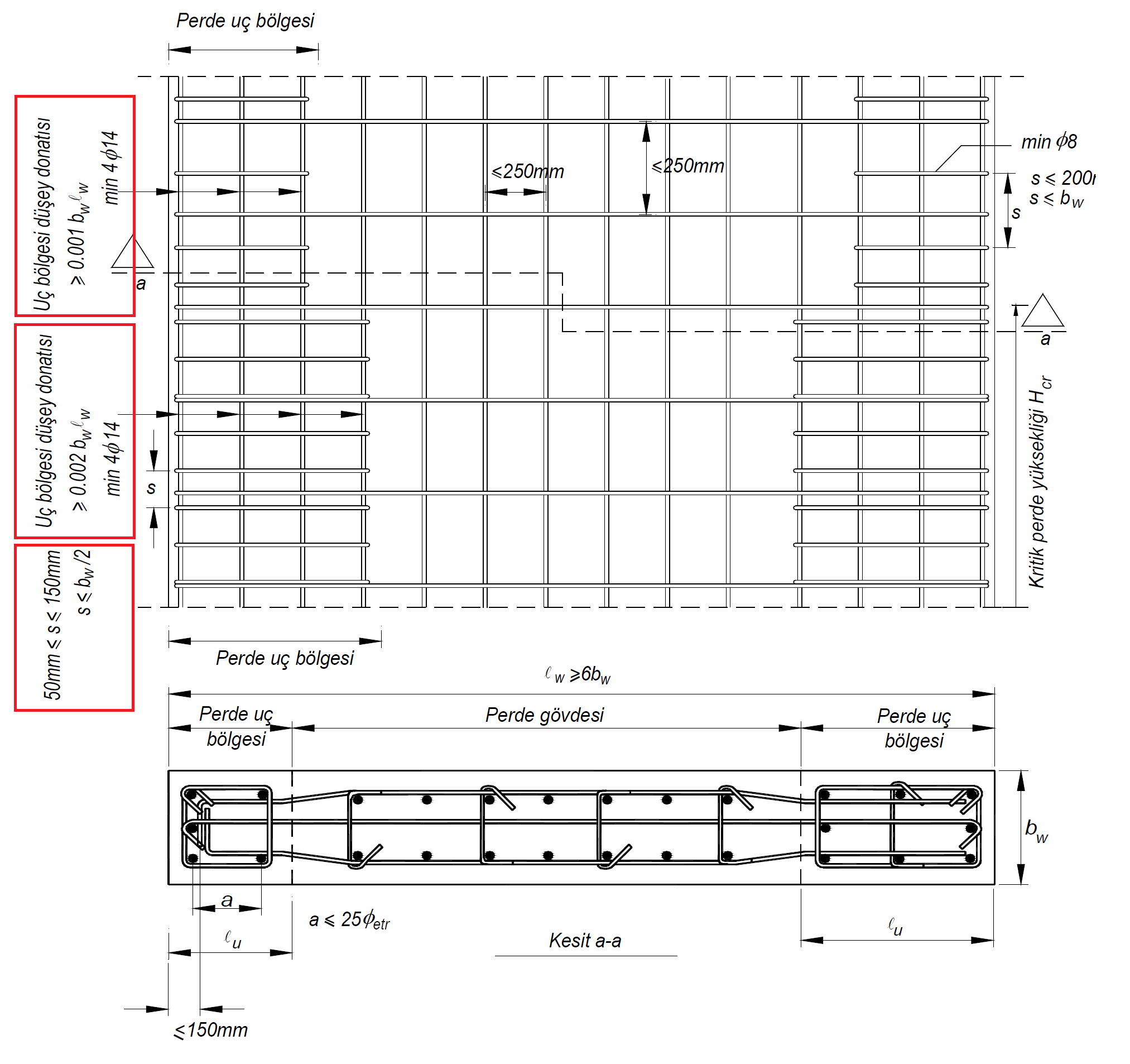
Vertical reinforcements at the wall end zones are wrapped with transverse reinforcements made of stirrups and / or crossties in accordance with the following rules, in accordance with Article 7.6.5.2 of TBDY .
-
Transverse reinforcement diameter is taken as minimum 8 mm in the end regions. The horizontal distance between the stirrup sleeves and crossties is taken less than 25 times the diameter of the stirrup and crotch.
-
The critical wall height for the confinement zones of the column of wall end along 7.3.4.1 from Eq. (7.1) "in the second condition and the determined at least transverse reinforcement 2/3 should be placed. This condition is controlled by the user.
-
In the vertical direction, the stirrup and / or tie-dye spacing is not taken larger than 150 mm and smaller than 50 mm.
-
In the vertical direction, the stirrup and / or crotch spacing is not taken more than 6 times the diameter of the reinforcement and 1/3 of the wall thickness.
-
The transverse reinforcements in the wall end zone are continued inside the foundation for a height not less than 300 mm and wall thickness.
-
The stirrups and / or trousers spacing in vertical direction in the wall end regions outside the critical wall height shall not be taken larger than the wall thickness and 200 mm.
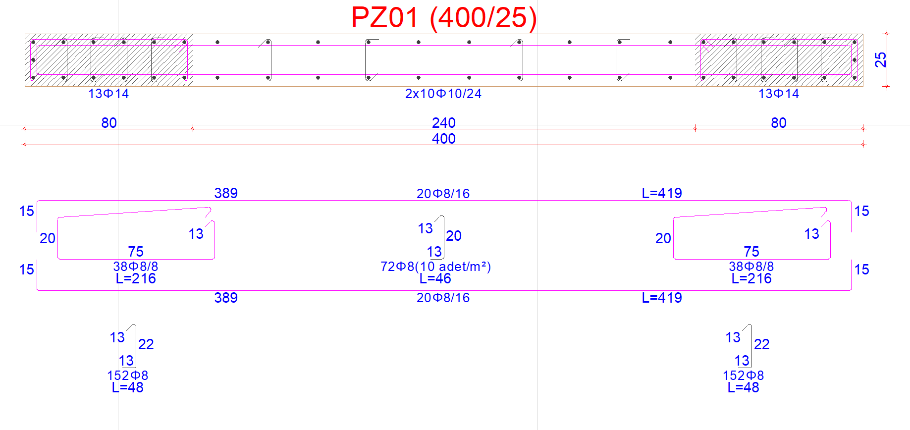
An example of a wall drawing created in accordance with TBDY Section 7.6.5 along the critical wall height is shown in the picture below.
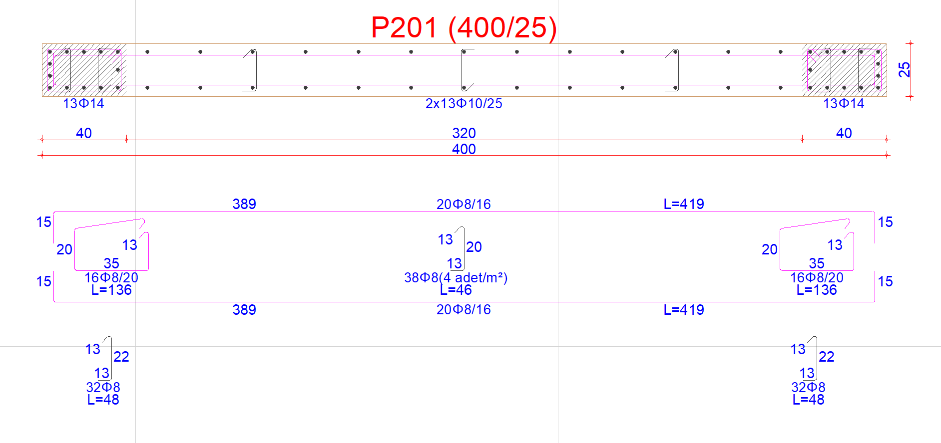
Similarly , an example of a wall drawing created in accordance with TBDY Section 7.6.5 in the upper part of the critical wall height is shown in the picture below.
Next Topic