
-
As stated in the conditions of TBDY 2018 4.5.1.1 and 4.5.1.2, the mathematical model of the building is generated in three dimensions. The seismic effect in two horizontal directions perpendicular to each other is taken into consideration.
-
Depending on the condition of TBDY 2018 4.5.1.3, the damping ratio has been taken as 5%.
-
Coupling beams are modeled as a frame element. Rigid arms are used at the junction points with the shearwalls modeled as shell elements.
-
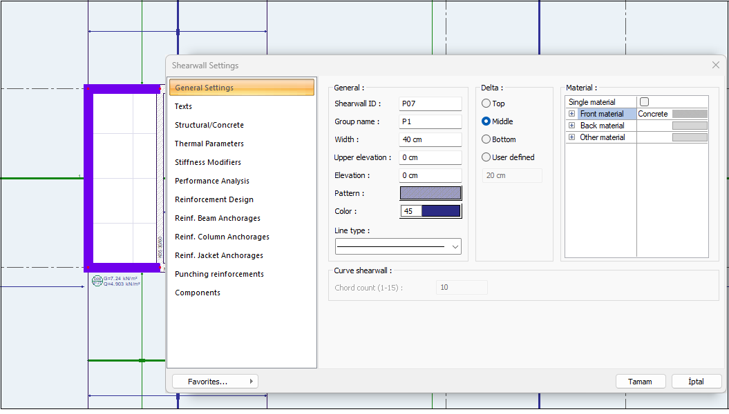
The core wall is obtained by connecting two U-shape shearwall with coupling beams. According to TBDY 2018 4.5.3.5 article, shearwall arms should not be modeled separately. For this reason, group pitch assignment must be made in the program. The shearwall arms that form the U - shape are selected and the group name part in the properties is filled. After this process, the program automatically determines the forces in accordance with seismic code at the center of the relevant wall group in the analysis.
-
Columns are modeled as frame elements.
-
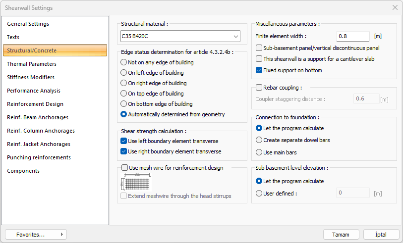
Walls are modeled with shell finite elements containing degrees of freedom for in-plane and out-of-plane displacements.
-
The shearwall finite element dimensions are modeled as 80 cm for a sufficiently accurate calculation of the internal force distribution.
-
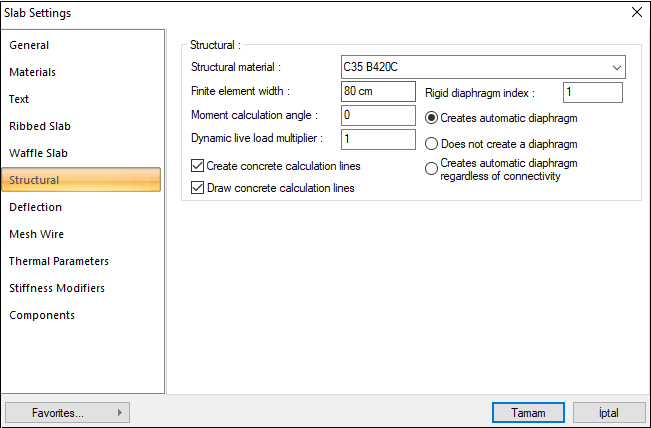
Slabs are modeled with shell finite elements containing degrees of freedom for both in-plane and out-of-plane displacements.
-
The slabs are modeled as 80 cm using a semi-rigid diaphragm in a finite element width to match the shearwalls.
-
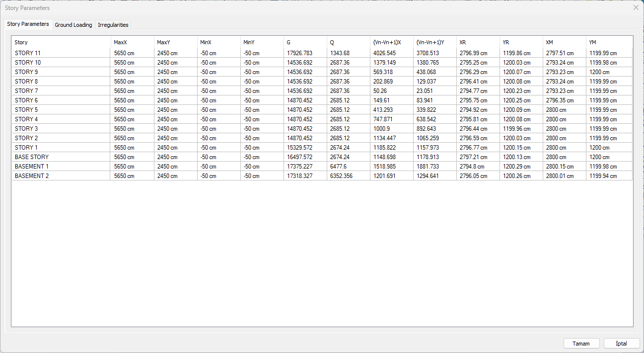
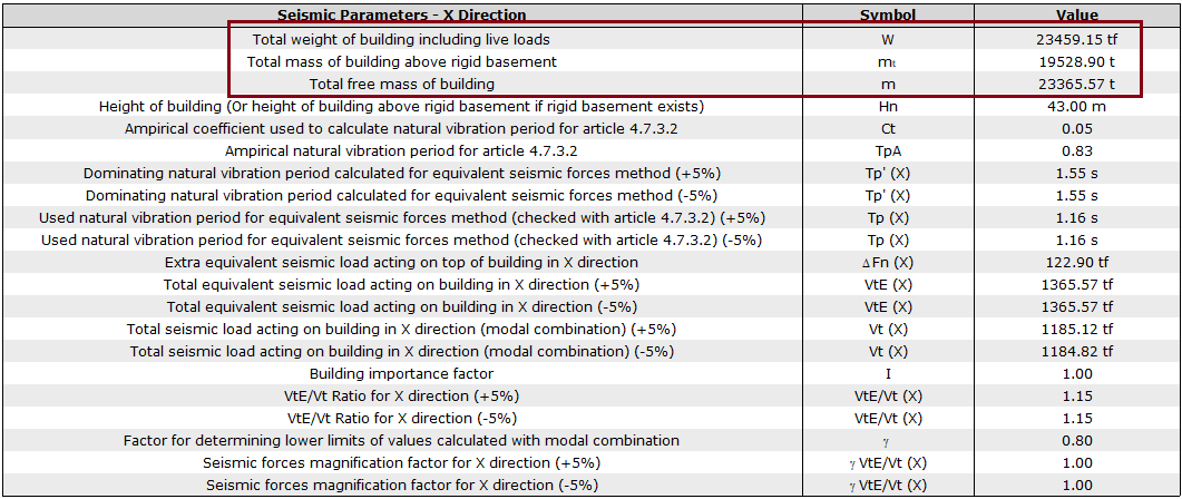
Live load reduction factor, n, is taken as 0.3 since the building is used as office. The total mass of the building is given in the dynamic analysis report entry section. At the same time, in the upper toolbar Analysis and Design tab, in the floor parameters section, G and Q are given separately for all floors.
-
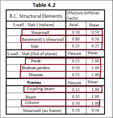
It is mandatory to use effective cross-section stiffness according to Table 4.2 in load combinations and loading situations involving seismic effects for structural system elements. Consisting of vertical loads only, G + Q, 1.4G + 1.6Q etc. effective section stiffness is not used in loadings. The program automatically applies the effective section stiffness.
-
The stiffnesses used in the building are shown in the red box on Table 4.2.
-
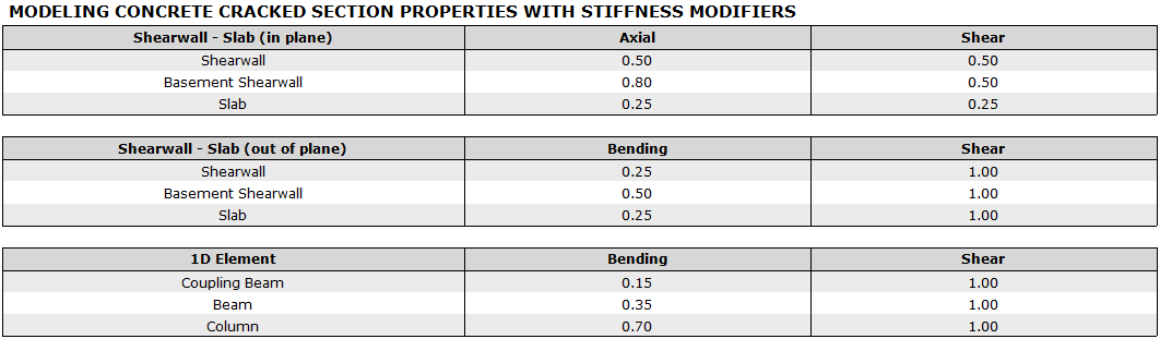
The same information is reported on the optional report in the program as follows.
Next Topic