
How does ideCAD calculate two-way shear strength according to ACI 318-19?
-
Two-Way shear strength of two-way members is calculated automatically
Notation
Av = area of shear reinforcement within spacing s, in.2
bo = perimeter of critical section for two-way shear in slabs and footings, in.
d = distance from extreme compression fiber to centroid of longitudinal tension reinforcement, in.
db = nominal diameter of bar, wire, or prestressing strand, in.
fc ' = specified compressive strength of concrete, psi
√fc‘ = square root of specified compressive strength of concrete, psi
fyt = specified yield strength of transverse reinforcement, psi
vc = stress corresponding to nominal two-way shear strength provided by concrete, psi
vn = equivalent concrete stress corresponding to the nominal two-way shear strength of slab or footing, psi
vs = equivalent concrete stress corresponding to nominal two-way shear strength provided by reinforcement, psi
vu = maximum factored two-way shear stress calculated around the perimeter of a given critical section, psi
αs = constant used to calculate Vc in slabs and footings
β = ratio of long to short dimensions; clear spans for two-way slabs, sides of column, concentrated load or reaction area; or sides of a footing
ϕ = strength reduction factor
λ = modification factor to reflect the reduced mechanical properties of lightweight concrete relative to normal-weight concrete of the same compressive strength
λs = factor used to modify shear strength based on the effects of member depth, commonly reffered to as the size effect factor
Download ideCAD for ACI 318-19
The nominal shear strength of the two-way members with shear reinforcement should be calculated by using ACI Eq.(22.6.1.3),
'%3e%3cg transform='translate(167%2c0)'%3e%3cg transform='translate(-13%2c0)'%3e%3cg transform='translate(0%2c-25)'%3e%3cuse xlink:href='%23MJMATHI-76' x='0' y='0'%3e%3c/use%3e%3cuse transform='scale(0.707)' xlink:href='%23MJMATHI-6E' x='686' y='-213'%3e%3c/use%3e%3cuse xlink:href='%23MJMAIN-3D' x='1287' y='0'%3e%3c/use%3e%3cg transform='translate(2344%2c0)'%3e%3cuse xlink:href='%23MJMATHI-76' x='0' y='0'%3e%3c/use%3e%3cuse transform='scale(0.707)' xlink:href='%23MJMATHI-63' x='686' y='-213'%3e%3c/use%3e%3c/g%3e%3cuse xlink:href='%23MJMAIN-2B' x='3458' y='0'%3e%3c/use%3e%3cg transform='translate(4459%2c0)'%3e%3cuse xlink:href='%23MJMATHI-76' x='0' y='0'%3e%3c/use%3e%3cuse transform='scale(0.707)' xlink:href='%23MJMATHI-73' x='686' y='-213'%3e%3c/use%3e%3c/g%3e%3cuse xlink:href='%23MJMAIN-28' x='11487' y='0'%3e%3c/use%3e%3cg transform='translate(11877%2c0)'%3e%3cuse xlink:href='%23MJMAIN-32'%3e%3c/use%3e%3cuse xlink:href='%23MJMAIN-32' x='500' y='0'%3e%3c/use%3e%3cuse xlink:href='%23MJMAIN-2E' x='1001' y='0'%3e%3c/use%3e%3cuse xlink:href='%23MJMAIN-36' x='1279' y='0'%3e%3c/use%3e%3cuse xlink:href='%23MJMAIN-2E' x='1780' y='0'%3e%3c/use%3e%3cuse xlink:href='%23MJMAIN-31' x='2058' y='0'%3e%3c/use%3e%3cuse xlink:href='%23MJMAIN-2E' x='2559' y='0'%3e%3c/use%3e%3cuse xlink:href='%23MJMAIN-33' x='2837' y='0'%3e%3c/use%3e%3c/g%3e%3cuse xlink:href='%23MJMAIN-29' x='15215' y='0'%3e%3c/use%3e%3c/g%3e%3c/g%3e%3c/g%3e%3c/g%3e%3c/svg%3e)
According to ACI 22.6.1.4, two-way shear strength should be calculated using a section with depth and critical perimeter bo, (defined in ACI 22.6.4).
According to ACI 22.6.2.1, for calculation of vc and vs for two-way shear, d should be the average of the effective depths in the orthogonal directions.
According to ACI 22.6.3.1, the maximum √fc‘ value is 100 psi.
Critical Sections for Two-way Members
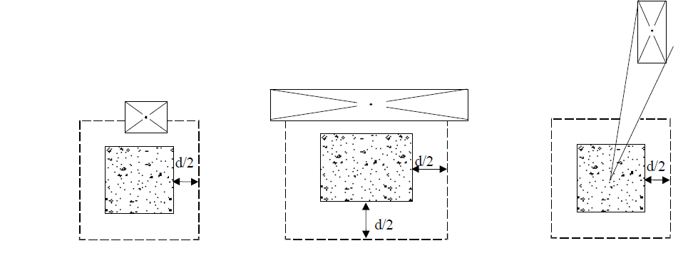
According to ACI 22.6.4.1, for two-way shear, critical sections should be located so that perimeter bo is a minimum but need not be closer than d/2 to given two cases given below;
-
Edges or corners of columns, concentrated loads, or reaction areas
-
Changes in slab or footing thickness, such as edges of capitals, drop panels, or shear caps
According to ACI 22.6.4.1.1, concentrated loads, or reaction areas, critical sections for two-way shear in accordance with ACI 22.6.4.1 (case 1 and case 2) can be defined assuming straight sides for square or rectangular columns.
According to ACI 22.6.4.1.2, critical sections for two-way shear in accordance with ACI 22.6.4.1 (case 1 and case 2) can be defined assuming a square column of equivalent area for a circular or regular polygon-shaped column.
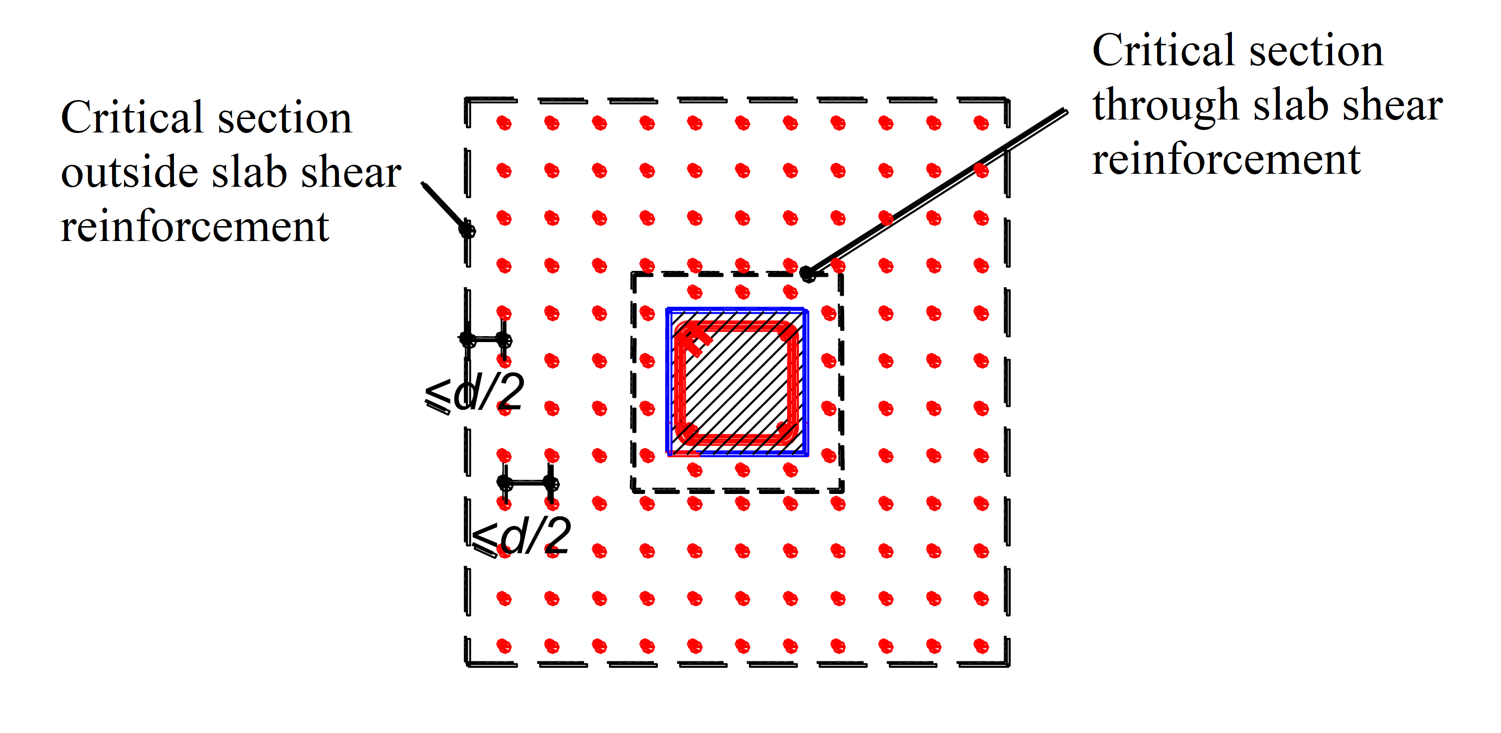
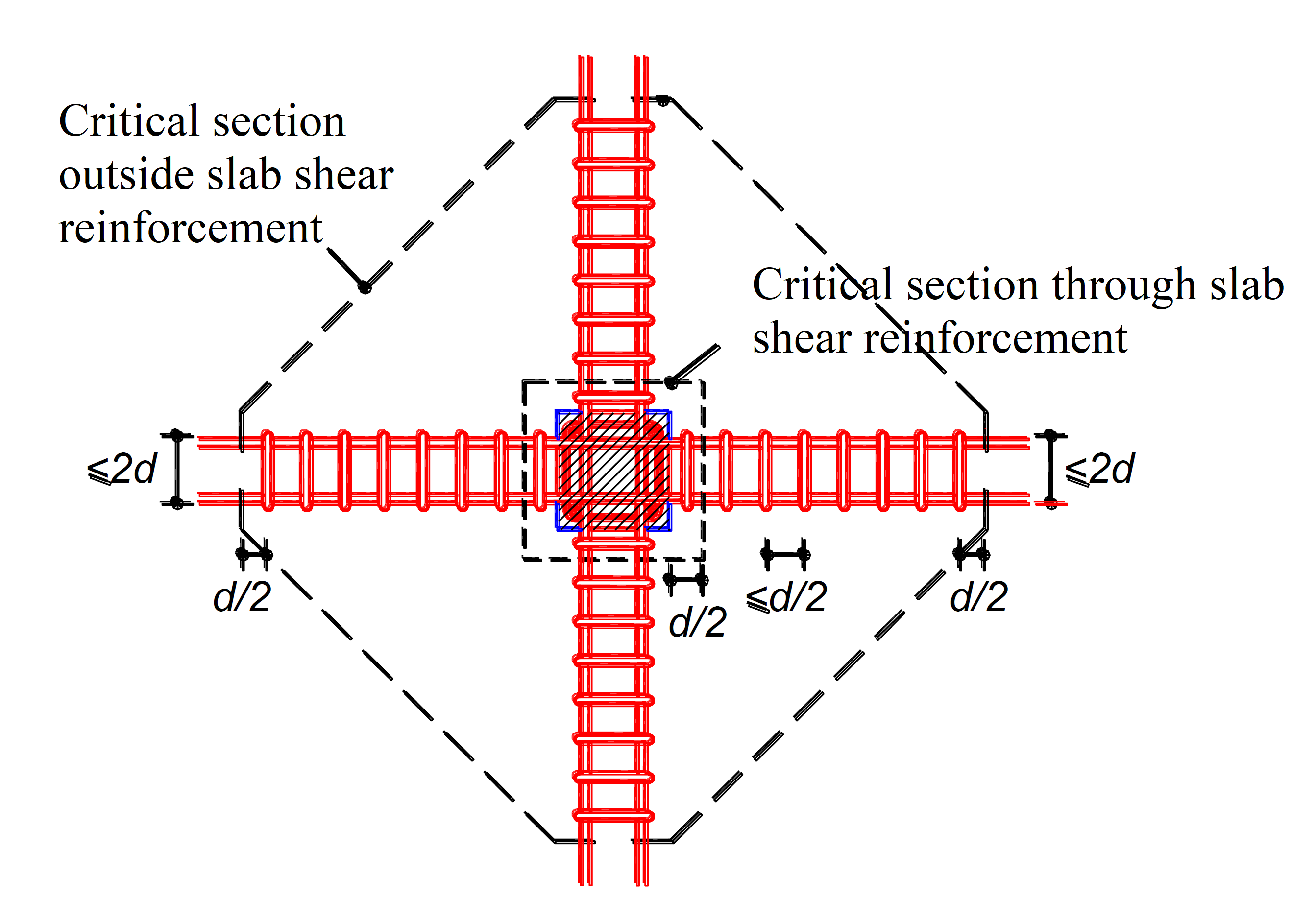
According to ACI 22.6.4.2, for two-way members with single (or multi) leg stirrup or headed stud shear reinforcement, one more critical section with perimeter bo located d/2 beyond the point where shear reinforcement is discontinued. The shape of this critical section should be a polygon selected to minimize bo.
The value of bo is shown in the figure below.
According to ACI 22.6.4.3, If there is an opening located closer than 4h from the periphery of a column, concentrated load, or reaction area, the portion of bo enclosed by straight lines projecting from the centroid of the column, concentrated load or reaction area and tangent to the boundaries of the opening should be considered ineffective.
Two-way Shear Strength Provided by Concrete in Members Without Shear Reinforcement
According to ACI 22.6.5.2, For nonprestressed two-way members, vc shall be calculated in accordance with ACI Table 22.6.5.2.
|
vc |
|
|
|---|---|---|
|
Least of (a), (b), and (c) |
|
(a) |
|
|
(b) |
|
|
|
(c) |
|
'%3e%3cg transform='translate(167%2c0)'%3e%3cg transform='translate(-13%2c0)'%3e%3cg transform='translate(0%2c-47)'%3e%3cuse xlink:href='%23MJMAIN-34' x='0' y='0'%3e%3c/use%3e%3cg transform='translate(500%2c0)'%3e%3cuse xlink:href='%23MJMATHI-3BB' x='0' y='0'%3e%3c/use%3e%3cuse transform='scale(0.707)' xlink:href='%23MJMATHI-73' x='825' y='-213'%3e%3c/use%3e%3c/g%3e%3cuse xlink:href='%23MJMATHI-3BB' x='1515' y='0'%3e%3c/use%3e%3cg transform='translate(2099%2c0)'%3e%3cuse xlink:href='%23MJSZ1-221A' x='0' y='16'%3e%3c/use%3e%3crect stroke='none' width='897' height='60' x='1000' y='807'%3e%3c/rect%3e%3cg transform='translate(1000%2c0)'%3e%3cuse xlink:href='%23MJMATHI-66' x='0' y='0'%3e%3c/use%3e%3cuse transform='scale(0.707)' xlink:href='%23MJMAIN-2032' x='804' y='445'%3e%3c/use%3e%3cuse transform='scale(0.707)' xlink:href='%23MJMATHI-63' x='693' y='-211'%3e%3c/use%3e%3c/g%3e%3c/g%3e%3c/g%3e%3c/g%3e%3c/g%3e%3c/g%3e%3c/svg%3e)
'%3e%3cg transform='translate(167%2c0)'%3e%3cg transform='translate(-13%2c0)'%3e%3cuse xlink:href='%23MJSZ2-28' x='0' y='-1'%3e%3c/use%3e%3cuse xlink:href='%23MJMAIN-32' x='597' y='0'%3e%3c/use%3e%3cuse xlink:href='%23MJMAIN-2B' x='1320' y='0'%3e%3c/use%3e%3cg transform='translate(2098%2c0)'%3e%3cg transform='translate(342%2c0)'%3e%3crect stroke='none' width='525' height='60' x='0' y='220'%3e%3c/rect%3e%3cuse transform='scale(0.707)' xlink:href='%23MJMAIN-34' x='121' y='602'%3e%3c/use%3e%3cuse transform='scale(0.707)' xlink:href='%23MJMATHI-3B2' x='84' y='-601'%3e%3c/use%3e%3c/g%3e%3c/g%3e%3cuse xlink:href='%23MJSZ2-29' x='3086' y='-1'%3e%3c/use%3e%3cg transform='translate(3683%2c0)'%3e%3cuse xlink:href='%23MJMATHI-3BB' x='0' y='0'%3e%3c/use%3e%3cuse transform='scale(0.707)' xlink:href='%23MJMATHI-73' x='825' y='-213'%3e%3c/use%3e%3c/g%3e%3cuse xlink:href='%23MJMATHI-3BB' x='4699' y='0'%3e%3c/use%3e%3cg transform='translate(5282%2c0)'%3e%3cuse xlink:href='%23MJSZ1-221A' x='0' y='16'%3e%3c/use%3e%3crect stroke='none' width='897' height='60' x='1000' y='807'%3e%3c/rect%3e%3cg transform='translate(1000%2c0)'%3e%3cuse xlink:href='%23MJMATHI-66' x='0' y='0'%3e%3c/use%3e%3cuse transform='scale(0.707)' xlink:href='%23MJMAIN-2032' x='804' y='445'%3e%3c/use%3e%3cuse transform='scale(0.707)' xlink:href='%23MJMATHI-63' x='693' y='-211'%3e%3c/use%3e%3c/g%3e%3c/g%3e%3c/g%3e%3c/g%3e%3c/g%3e%3c/svg%3e)
'%3e%3cg transform='translate(167%2c0)'%3e%3cg transform='translate(-13%2c0)'%3e%3cuse xlink:href='%23MJSZ2-28' x='0' y='-1'%3e%3c/use%3e%3cuse xlink:href='%23MJMAIN-32' x='597' y='0'%3e%3c/use%3e%3cuse xlink:href='%23MJMAIN-2B' x='1320' y='0'%3e%3c/use%3e%3cg transform='translate(2098%2c0)'%3e%3cg transform='translate(342%2c0)'%3e%3crect stroke='none' width='1248' height='60' x='0' y='220'%3e%3c/rect%3e%3cg transform='translate(60%2c536)'%3e%3cuse transform='scale(0.707)' xlink:href='%23MJMATHI-3B1' x='0' y='0'%3e%3c/use%3e%3cuse transform='scale(0.5)' xlink:href='%23MJMATHI-73' x='905' y='-213'%3e%3c/use%3e%3cuse transform='scale(0.707)' xlink:href='%23MJMATHI-64' x='1072' y='0'%3e%3c/use%3e%3c/g%3e%3cg transform='translate(315%2c-417)'%3e%3cuse transform='scale(0.707)' xlink:href='%23MJMATHI-62' x='0' y='0'%3e%3c/use%3e%3cuse transform='scale(0.5)' xlink:href='%23MJMATHI-6F' x='607' y='-213'%3e%3c/use%3e%3c/g%3e%3c/g%3e%3c/g%3e%3cuse xlink:href='%23MJSZ2-29' x='3809' y='-1'%3e%3c/use%3e%3cg transform='translate(4406%2c0)'%3e%3cuse xlink:href='%23MJMATHI-3BB' x='0' y='0'%3e%3c/use%3e%3cuse transform='scale(0.707)' xlink:href='%23MJMATHI-73' x='825' y='-213'%3e%3c/use%3e%3c/g%3e%3cuse xlink:href='%23MJMATHI-3BB' x='5422' y='0'%3e%3c/use%3e%3cg transform='translate(6005%2c0)'%3e%3cuse xlink:href='%23MJSZ1-221A' x='0' y='16'%3e%3c/use%3e%3crect stroke='none' width='897' height='60' x='1000' y='807'%3e%3c/rect%3e%3cg transform='translate(1000%2c0)'%3e%3cuse xlink:href='%23MJMATHI-66' x='0' y='0'%3e%3c/use%3e%3cuse transform='scale(0.707)' xlink:href='%23MJMAIN-2032' x='804' y='445'%3e%3c/use%3e%3cuse transform='scale(0.707)' xlink:href='%23MJMATHI-63' x='693' y='-211'%3e%3c/use%3e%3c/g%3e%3c/g%3e%3c/g%3e%3c/g%3e%3c/g%3e%3c/svg%3e)
According to ACI 22.6.5.3, αs value is
-
40 for interior columns
-
30 for edge columns
-
20 for corner columns
Two-way Shear Strength Provided by Concrete in Members With Shear Reinforcement
According to ACI 22.6.6.1, for nonprestressed two-way members with shear reinforcement, vc at critical sections should be calculated in accordance with ACI Table 22.6.6.1.
Type of shear reinforcement
|
Critical sections |
vc |
|
|
|---|---|---|---|---|
|
Stirrups |
All |
|
(a) |
|
|
Headed shear stud reinforcement |
According to 22.6.4.1 |
Least of (b), (c), and (d) |
|
(b) |
|
|
(c) |
|||
|
|
(d) |
|||
|
According to 22.6.4.2 |
|
|
(e) |
|
'%3e%3cg transform='translate(167%2c0)'%3e%3cg transform='translate(-13%2c0)'%3e%3cg transform='translate(0%2c-47)'%3e%3cuse xlink:href='%23MJMAIN-32' x='0' y='0'%3e%3c/use%3e%3cg transform='translate(500%2c0)'%3e%3cuse xlink:href='%23MJMATHI-3BB' x='0' y='0'%3e%3c/use%3e%3cuse transform='scale(0.707)' xlink:href='%23MJMATHI-73' x='825' y='-213'%3e%3c/use%3e%3c/g%3e%3cuse xlink:href='%23MJMATHI-3BB' x='1515' y='0'%3e%3c/use%3e%3cg transform='translate(2099%2c0)'%3e%3cuse xlink:href='%23MJSZ1-221A' x='0' y='16'%3e%3c/use%3e%3crect stroke='none' width='897' height='60' x='1000' y='807'%3e%3c/rect%3e%3cg transform='translate(1000%2c0)'%3e%3cuse xlink:href='%23MJMATHI-66' x='0' y='0'%3e%3c/use%3e%3cuse transform='scale(0.707)' xlink:href='%23MJMAIN-2032' x='804' y='445'%3e%3c/use%3e%3cuse transform='scale(0.707)' xlink:href='%23MJMATHI-63' x='693' y='-211'%3e%3c/use%3e%3c/g%3e%3c/g%3e%3c/g%3e%3c/g%3e%3c/g%3e%3c/g%3e%3c/svg%3e)
'%3e%3cg transform='translate(167%2c0)'%3e%3cg transform='translate(-13%2c0)'%3e%3cg transform='translate(0%2c-47)'%3e%3cuse xlink:href='%23MJMAIN-33' x='0' y='0'%3e%3c/use%3e%3cg transform='translate(500%2c0)'%3e%3cuse xlink:href='%23MJMATHI-3BB' x='0' y='0'%3e%3c/use%3e%3cuse transform='scale(0.707)' xlink:href='%23MJMATHI-73' x='825' y='-213'%3e%3c/use%3e%3c/g%3e%3cuse xlink:href='%23MJMATHI-3BB' x='1515' y='0'%3e%3c/use%3e%3cg transform='translate(2099%2c0)'%3e%3cuse xlink:href='%23MJSZ1-221A' x='0' y='16'%3e%3c/use%3e%3crect stroke='none' width='897' height='60' x='1000' y='807'%3e%3c/rect%3e%3cg transform='translate(1000%2c0)'%3e%3cuse xlink:href='%23MJMATHI-66' x='0' y='0'%3e%3c/use%3e%3cuse transform='scale(0.707)' xlink:href='%23MJMAIN-2032' x='804' y='445'%3e%3c/use%3e%3cuse transform='scale(0.707)' xlink:href='%23MJMATHI-63' x='693' y='-211'%3e%3c/use%3e%3c/g%3e%3c/g%3e%3c/g%3e%3c/g%3e%3c/g%3e%3c/g%3e%3c/svg%3e)
The size effect modification factor, λs
'%3e%3cg transform='translate(167%2c0)'%3e%3cg transform='translate(-13%2c0)'%3e%3cg transform='translate(0%2c244)'%3e%3cuse xlink:href='%23MJMATHI-3BB' x='0' y='0'%3e%3c/use%3e%3cuse transform='scale(0.707)' xlink:href='%23MJMATHI-73' x='825' y='-213'%3e%3c/use%3e%3cuse xlink:href='%23MJMAIN-3D' x='1293' y='0'%3e%3c/use%3e%3cg transform='translate(2349%2c0)'%3e%3cuse xlink:href='%23MJSZ3-221A' x='0' y='-275'%3e%3c/use%3e%3crect stroke='none' width='2124' height='60' x='1000' y='1116'%3e%3c/rect%3e%3cg transform='translate(1000%2c0)'%3e%3cg transform='translate(120%2c0)'%3e%3crect stroke='none' width='1884' height='60' x='0' y='220'%3e%3c/rect%3e%3cuse transform='scale(0.707)' xlink:href='%23MJMAIN-32' x='1082' y='602'%3e%3c/use%3e%3cg transform='translate(60%2c-631)'%3e%3cuse transform='scale(0.707)' xlink:href='%23MJMAIN-31' x='0' y='0'%3e%3c/use%3e%3cuse transform='scale(0.707)' xlink:href='%23MJMAIN-2B' x='500' y='0'%3e%3c/use%3e%3cg transform='translate(904%2c0)'%3e%3cg transform='translate(120%2c0)'%3e%3crect stroke='none' width='620' height='60' x='0' y='146'%3e%3c/rect%3e%3cuse transform='scale(0.5)' xlink:href='%23MJMATHI-64' x='358' y='715'%3e%3c/use%3e%3cg transform='translate(60%2c-333)'%3e%3cuse transform='scale(0.5)' xlink:href='%23MJMAIN-31'%3e%3c/use%3e%3cuse transform='scale(0.5)' xlink:href='%23MJMAIN-30' x='500' y='0'%3e%3c/use%3e%3c/g%3e%3c/g%3e%3c/g%3e%3c/g%3e%3c/g%3e%3c/g%3e%3c/g%3e%3cuse xlink:href='%23MJMAIN-2264' x='5752' y='0'%3e%3c/use%3e%3cuse xlink:href='%23MJMAIN-31' x='6808' y='0'%3e%3c/use%3e%3c/g%3e%3c/g%3e%3c/g%3e%3c/g%3e%3c/svg%3e)
According to ACI 22.6.6.2, the value of λs can be taken as 1.0 if the two conditions below are satisfied;
-
Stirrups are designed and detailed in accordance with ACI 8.7.6 and Av/s ≥ 2√fc‘bo/fyt
-
Smooth-headed shear stud reinforcement with stud shaft length not exceeding 10 in. is designed and detailed in accordance with ACI 8.7.7 and Av/s ≥ 2√fc‘bo/fyt
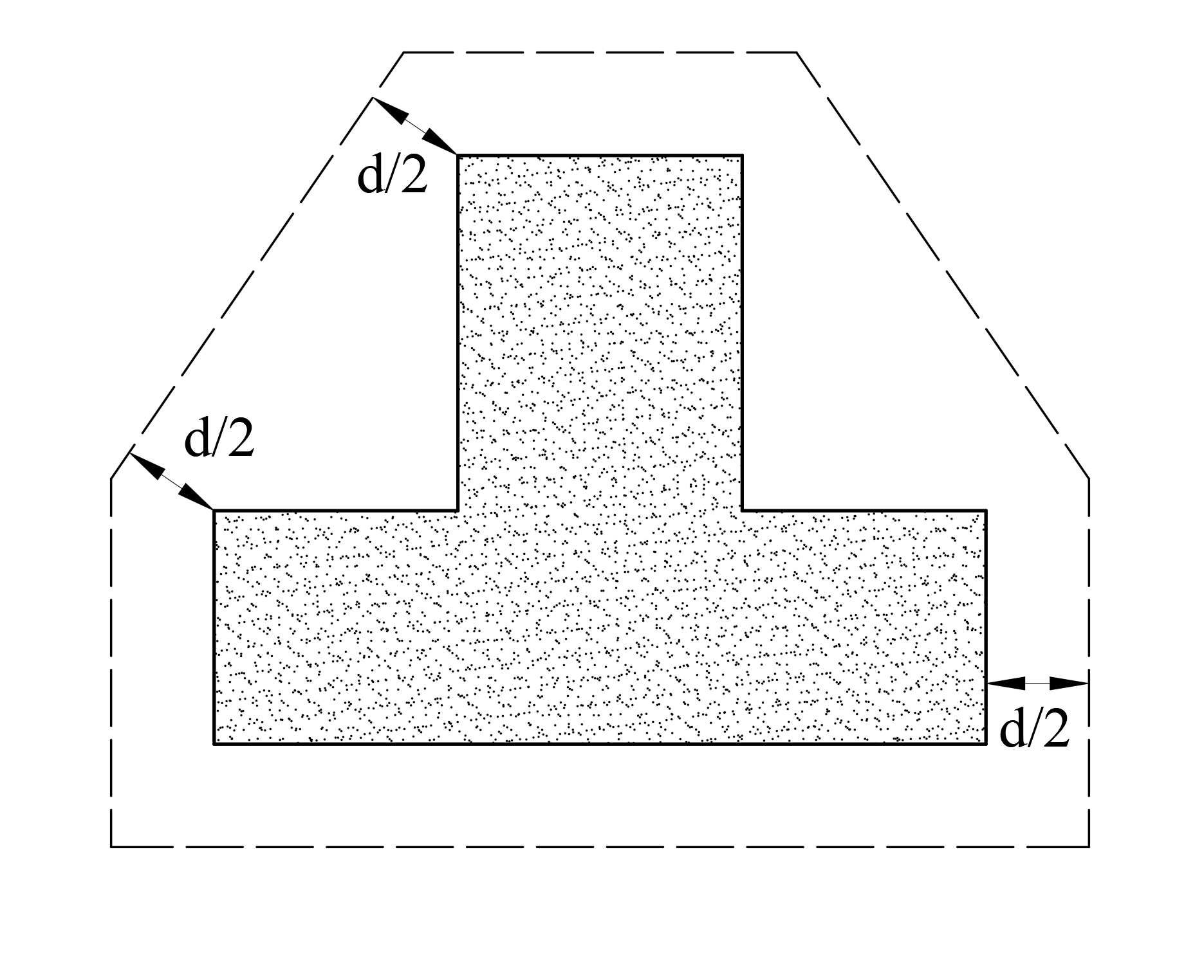
For shapes other than rectangular, β is taken to be the ratio of the longest dimension of the effective loaded area to the largest overall perpendicular dimension of the effective loaded area, as illustrated for an L-shaped reaction area in ACI Fig. R22.6.5.2. Critical section of shapes other than rectangular is shown in the figure below.
According to ACI 22.6.6.3, for two-way members with shear reinforcement, the maximum effective depth should be selected such that vu calculated at critical sections is given in ACI Table 22.6.6.3.
|
Type of shear reinforcement |
Maximum vu at critical section |
|
|---|---|---|
|
Stirrups |
|
(a) |
|
Headed shear stud reinforcement |
|
(b) |
'%3e%3cg transform='translate(167%2c0)'%3e%3cg transform='translate(-13%2c0)'%3e%3cg transform='translate(0%2c-47)'%3e%3cuse xlink:href='%23MJMATHI-3D5' x='0' y='0'%3e%3c/use%3e%3cuse xlink:href='%23MJMAIN-36' x='596' y='0'%3e%3c/use%3e%3cg transform='translate(1097%2c0)'%3e%3cuse xlink:href='%23MJSZ1-221A' x='0' y='16'%3e%3c/use%3e%3crect stroke='none' width='897' height='60' x='1000' y='807'%3e%3c/rect%3e%3cg transform='translate(1000%2c0)'%3e%3cuse xlink:href='%23MJMATHI-66' x='0' y='0'%3e%3c/use%3e%3cuse transform='scale(0.707)' xlink:href='%23MJMAIN-2032' x='804' y='445'%3e%3c/use%3e%3cuse transform='scale(0.707)' xlink:href='%23MJMATHI-63' x='693' y='-211'%3e%3c/use%3e%3c/g%3e%3c/g%3e%3c/g%3e%3c/g%3e%3c/g%3e%3c/g%3e%3c/svg%3e)
'%3e%3cg transform='translate(167%2c0)'%3e%3cg transform='translate(-13%2c0)'%3e%3cg transform='translate(0%2c-47)'%3e%3cuse xlink:href='%23MJMATHI-3D5' x='0' y='0'%3e%3c/use%3e%3cuse xlink:href='%23MJMAIN-38' x='596' y='0'%3e%3c/use%3e%3cg transform='translate(1097%2c0)'%3e%3cuse xlink:href='%23MJSZ1-221A' x='0' y='16'%3e%3c/use%3e%3crect stroke='none' width='897' height='60' x='1000' y='807'%3e%3c/rect%3e%3cg transform='translate(1000%2c0)'%3e%3cuse xlink:href='%23MJMATHI-66' x='0' y='0'%3e%3c/use%3e%3cuse transform='scale(0.707)' xlink:href='%23MJMAIN-2032' x='804' y='445'%3e%3c/use%3e%3cuse transform='scale(0.707)' xlink:href='%23MJMATHI-63' x='693' y='-211'%3e%3c/use%3e%3c/g%3e%3c/g%3e%3c/g%3e%3c/g%3e%3c/g%3e%3c/g%3e%3c/svg%3e)
Two-way Shear Strength Provided by Single (or multiple) Leg Stirrups
According to ACI 22.6.7.1, Single (or multiple) leg stirrups fabricated from bars or wires can be used as shear reinforcement in slabs and footings satisfying given two conditions below;
-
d ≥ 6 inches
-
d ≥ 16db , where db is the diameter of the stirrups
According to ACI 22.6.7.2, for nonprestressed two-way members with single (or multiple) leg stirrups, vc should be calculated in accordance with ACI Eq. 22.6.7.2.
'%3e%3cg transform='translate(167%2c0)'%3e%3cg transform='translate(-13%2c0)'%3e%3cg transform='translate(0%2c-89)'%3e%3cuse xlink:href='%23MJMATHI-76' x='0' y='0'%3e%3c/use%3e%3cuse transform='scale(0.707)' xlink:href='%23MJMATHI-73' x='686' y='-213'%3e%3c/use%3e%3cuse xlink:href='%23MJMAIN-3D' x='1195' y='0'%3e%3c/use%3e%3cg transform='translate(1973%2c0)'%3e%3cg transform='translate(397%2c0)'%3e%3crect stroke='none' width='1811' height='60' x='0' y='220'%3e%3c/rect%3e%3cg transform='translate(60%2c698)'%3e%3cuse transform='scale(0.707)' xlink:href='%23MJMATHI-41' x='0' y='0'%3e%3c/use%3e%3cuse transform='scale(0.5)' xlink:href='%23MJMATHI-76' x='1061' y='-213'%3e%3c/use%3e%3cg transform='translate(844%2c0)'%3e%3cuse transform='scale(0.707)' xlink:href='%23MJMATHI-66' x='0' y='0'%3e%3c/use%3e%3cg transform='translate(346%2c-171)'%3e%3cuse transform='scale(0.5)' xlink:href='%23MJMATHI-79' x='0' y='0'%3e%3c/use%3e%3cuse transform='scale(0.5)' xlink:href='%23MJMATHI-74' x='497' y='0'%3e%3c/use%3e%3c/g%3e%3c/g%3e%3c/g%3e%3cg transform='translate(431%2c-417)'%3e%3cuse transform='scale(0.707)' xlink:href='%23MJMATHI-62' x='0' y='0'%3e%3c/use%3e%3cuse transform='scale(0.5)' xlink:href='%23MJMATHI-6F' x='607' y='-213'%3e%3c/use%3e%3cuse transform='scale(0.707)' xlink:href='%23MJMATHI-73' x='872' y='0'%3e%3c/use%3e%3c/g%3e%3c/g%3e%3c/g%3e%3cuse xlink:href='%23MJMAIN-28' x='10413' y='0'%3e%3c/use%3e%3cg transform='translate(10803%2c0)'%3e%3cuse xlink:href='%23MJMAIN-32'%3e%3c/use%3e%3cuse xlink:href='%23MJMAIN-32' x='500' y='0'%3e%3c/use%3e%3cuse xlink:href='%23MJMAIN-2E' x='1001' y='0'%3e%3c/use%3e%3cuse xlink:href='%23MJMAIN-36' x='1279' y='0'%3e%3c/use%3e%3cuse xlink:href='%23MJMAIN-2E' x='1780' y='0'%3e%3c/use%3e%3cuse xlink:href='%23MJMAIN-37' x='2058' y='0'%3e%3c/use%3e%3cuse xlink:href='%23MJMAIN-2E' x='2559' y='0'%3e%3c/use%3e%3cuse xlink:href='%23MJMAIN-32' x='2837' y='0'%3e%3c/use%3e%3c/g%3e%3cuse xlink:href='%23MJMAIN-29' x='14141' y='0'%3e%3c/use%3e%3c/g%3e%3c/g%3e%3c/g%3e%3c/g%3e%3c/svg%3e)
Av is the sum of the area of all legs of reinforcement on one peripheral line that is geometrically similar to the perimeter of the column section, and s is the spacing of the peripheral lines of shear reinforcement in the direction perpendicular to the column face.
Two-way Shear Strength Provided by Headed Shear Stud Reinforcement
According to ACI 22.6.8.1, the Headed shear stud reinforcement can be used as shear reinforcement in slabs and footings if the placement and geometry of the headed shear stud reinforcement satisfies ACI 8.7.7.
According to ACI 22.6.8.2, for nonprestressed two-way members with headed shear stud reinforcement, vc should be calculated in accordance with ACI Eq. 22.6.8.2.
'%3e%3cg transform='translate(167%2c0)'%3e%3cg transform='translate(-13%2c0)'%3e%3cg transform='translate(0%2c-89)'%3e%3cuse xlink:href='%23MJMATHI-76' x='0' y='0'%3e%3c/use%3e%3cuse transform='scale(0.707)' xlink:href='%23MJMATHI-73' x='686' y='-213'%3e%3c/use%3e%3cuse xlink:href='%23MJMAIN-3D' x='1195' y='0'%3e%3c/use%3e%3cg transform='translate(1973%2c0)'%3e%3cg transform='translate(397%2c0)'%3e%3crect stroke='none' width='1811' height='60' x='0' y='220'%3e%3c/rect%3e%3cg transform='translate(60%2c698)'%3e%3cuse transform='scale(0.707)' xlink:href='%23MJMATHI-41' x='0' y='0'%3e%3c/use%3e%3cuse transform='scale(0.5)' xlink:href='%23MJMATHI-76' x='1061' y='-213'%3e%3c/use%3e%3cg transform='translate(844%2c0)'%3e%3cuse transform='scale(0.707)' xlink:href='%23MJMATHI-66' x='0' y='0'%3e%3c/use%3e%3cg transform='translate(346%2c-171)'%3e%3cuse transform='scale(0.5)' xlink:href='%23MJMATHI-79' x='0' y='0'%3e%3c/use%3e%3cuse transform='scale(0.5)' xlink:href='%23MJMATHI-74' x='497' y='0'%3e%3c/use%3e%3c/g%3e%3c/g%3e%3c/g%3e%3cg transform='translate(431%2c-417)'%3e%3cuse transform='scale(0.707)' xlink:href='%23MJMATHI-62' x='0' y='0'%3e%3c/use%3e%3cuse transform='scale(0.5)' xlink:href='%23MJMATHI-6F' x='607' y='-213'%3e%3c/use%3e%3cuse transform='scale(0.707)' xlink:href='%23MJMATHI-73' x='872' y='0'%3e%3c/use%3e%3c/g%3e%3c/g%3e%3c/g%3e%3cuse xlink:href='%23MJMAIN-28' x='10413' y='0'%3e%3c/use%3e%3cg transform='translate(10803%2c0)'%3e%3cuse xlink:href='%23MJMAIN-32'%3e%3c/use%3e%3cuse xlink:href='%23MJMAIN-32' x='500' y='0'%3e%3c/use%3e%3cuse xlink:href='%23MJMAIN-2E' x='1001' y='0'%3e%3c/use%3e%3cuse xlink:href='%23MJMAIN-36' x='1279' y='0'%3e%3c/use%3e%3cuse xlink:href='%23MJMAIN-2E' x='1780' y='0'%3e%3c/use%3e%3cuse xlink:href='%23MJMAIN-38' x='2058' y='0'%3e%3c/use%3e%3cuse xlink:href='%23MJMAIN-2E' x='2559' y='0'%3e%3c/use%3e%3cuse xlink:href='%23MJMAIN-32' x='2837' y='0'%3e%3c/use%3e%3c/g%3e%3cuse xlink:href='%23MJMAIN-29' x='14141' y='0'%3e%3c/use%3e%3c/g%3e%3c/g%3e%3c/g%3e%3c/g%3e%3c/svg%3e)
Av is the sum of the area of all shear studs on one peripheral line geometrically similar to the perimeter of the column section, and s is the spacing of the peripheral lines of headed shear stud reinforcement in the direction perpendicular to the column face.
According to ACI 22.6.8.3, If headed shear stud reinforcement is provided, Av/s should satisfy ACI Eq. 22.6.8.3.
'%3e%3cg transform='translate(167%2c0)'%3e%3cg transform='translate(-13%2c0)'%3e%3cg transform='translate(0%2c76)'%3e%3cg transform='translate(120%2c0)'%3e%3crect stroke='none' width='964' height='60' x='0' y='220'%3e%3c/rect%3e%3cg transform='translate(60%2c537)'%3e%3cuse transform='scale(0.707)' xlink:href='%23MJMATHI-41' x='0' y='0'%3e%3c/use%3e%3cuse transform='scale(0.5)' xlink:href='%23MJMATHI-76' x='1061' y='-213'%3e%3c/use%3e%3c/g%3e%3cuse transform='scale(0.707)' xlink:href='%23MJMATHI-73' x='447' y='-488'%3e%3c/use%3e%3c/g%3e%3cuse xlink:href='%23MJMAIN-2265' x='1481' y='0'%3e%3c/use%3e%3cuse xlink:href='%23MJMAIN-32' x='2538' y='0'%3e%3c/use%3e%3cg transform='translate(3038%2c0)'%3e%3cuse xlink:href='%23MJSZ1-221A' x='0' y='16'%3e%3c/use%3e%3crect stroke='none' width='897' height='60' x='1000' y='807'%3e%3c/rect%3e%3cg transform='translate(1000%2c0)'%3e%3cuse xlink:href='%23MJMATHI-66' x='0' y='0'%3e%3c/use%3e%3cuse transform='scale(0.707)' xlink:href='%23MJMAIN-2032' x='804' y='445'%3e%3c/use%3e%3cuse transform='scale(0.707)' xlink:href='%23MJMATHI-63' x='693' y='-211'%3e%3c/use%3e%3c/g%3e%3c/g%3e%3cg transform='translate(4936%2c0)'%3e%3cg transform='translate(120%2c0)'%3e%3crect stroke='none' width='967' height='60' x='0' y='220'%3e%3c/rect%3e%3cg transform='translate(174%2c537)'%3e%3cuse transform='scale(0.707)' xlink:href='%23MJMATHI-62' x='0' y='0'%3e%3c/use%3e%3cuse transform='scale(0.5)' xlink:href='%23MJMATHI-6F' x='607' y='-213'%3e%3c/use%3e%3c/g%3e%3cg transform='translate(60%2c-425)'%3e%3cuse transform='scale(0.707)' xlink:href='%23MJMATHI-66' x='0' y='0'%3e%3c/use%3e%3cg transform='translate(346%2c-171)'%3e%3cuse transform='scale(0.5)' xlink:href='%23MJMATHI-79' x='0' y='0'%3e%3c/use%3e%3cuse transform='scale(0.5)' xlink:href='%23MJMATHI-74' x='497' y='0'%3e%3c/use%3e%3c/g%3e%3c/g%3e%3c/g%3e%3c/g%3e%3cuse xlink:href='%23MJMAIN-28' x='12254' y='0'%3e%3c/use%3e%3cg transform='translate(12643%2c0)'%3e%3cuse xlink:href='%23MJMAIN-32'%3e%3c/use%3e%3cuse xlink:href='%23MJMAIN-32' x='500' y='0'%3e%3c/use%3e%3cuse xlink:href='%23MJMAIN-2E' x='1001' y='0'%3e%3c/use%3e%3cuse xlink:href='%23MJMAIN-36' x='1279' y='0'%3e%3c/use%3e%3cuse xlink:href='%23MJMAIN-2E' x='1780' y='0'%3e%3c/use%3e%3cuse xlink:href='%23MJMAIN-38' x='2058' y='0'%3e%3c/use%3e%3cuse xlink:href='%23MJMAIN-2E' x='2559' y='0'%3e%3c/use%3e%3cuse xlink:href='%23MJMAIN-33' x='2837' y='0'%3e%3c/use%3e%3c/g%3e%3cuse xlink:href='%23MJMAIN-29' x='15981' y='0'%3e%3c/use%3e%3c/g%3e%3c/g%3e%3c/g%3e%3c/g%3e%3c/svg%3e)