
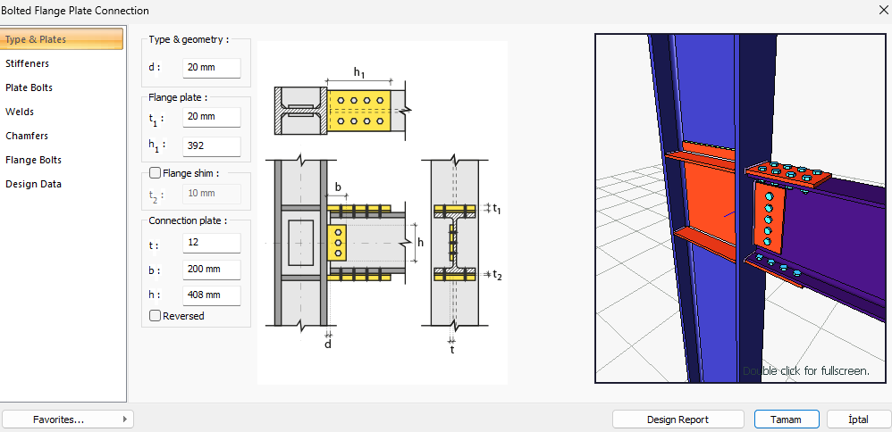
How does ideCAD design Bolted Flange Plate Connections according to AISC 358-16 & AISC 360-16?
-
Design limit states of bolted flange plate connections are calculated automatically according to AISC 358-16 and AISC 360-16.
Symbols
Ab: Non-threaded bolt web characteristic cross-sectional area
Ag: Gross area
An: Net cross-section area
Ae: Effective net cross-sectional area
Avg: Gross area under shear stress
Anv: Net area under shear stress
Ant: Net area under tensile stress
Aw: Cross-section web area
bbf = width of beam flange, in. (mm)
bp = width of end-plate, in. (mm)
d = depth of connecting beam, in. (mm)
g = horizontal distance between bolts, in. (mm)
dh: Bolt hole diameter
Fy: Structural steel characteristic yield strength
Fu: Structural steel characteristic tensile strength
Fyb: Bolt characteristic yield strength
Fub: Bolt characteristic tensile strength
nsp: Number of slip planes
s: Distance between bolt-hole centers
L: Connector distance
Lc: The clear distance between bolt holes
Le: The distance from the center of the bolt hole to the edge of the assembled element
Leh: The horizontal distance from the center of the bolt hole to the edge of the assembled element
Lev: The vertical distance from the center of the bolt hole to the edge of the assembled element
pb = vertical distance between the inner and outer row of bolts in an eight-bolt stiffened connection, in. (mm)
pfi = vertical distance from the inside of a beam tension flange to the nearest inside bolt row, in. (mm)
pfo = vertical distance from the outside of a beam tension flange to the nearest outside bolt row, in. (mm)
tbf = thickness of beam flange, in. (mm)
tp = thickness of end-plate, in. (mm)
Rn: Characteristic strength
Connection Geometry
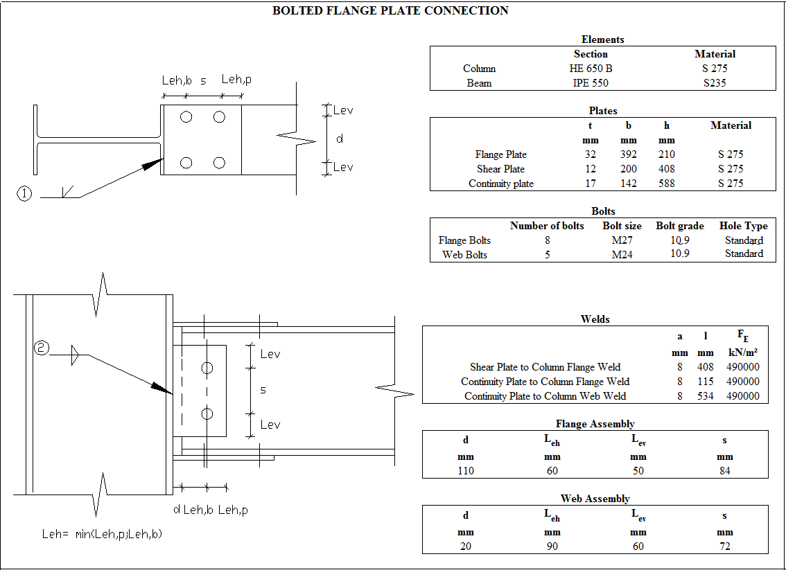
GEOMETRY CHECKS
Bolt Spacing at Flange
The distance between the centers of bolts is checked per AISC 360-16.
|
smin ≥ 3d |
AISC 360-16 J3.3 |
|
|
|
s |
84 mm |
|
|
|
d |
27 mm |
s =84 mm > smin = 3*27=81 mm |
√ |
Horizontal Edge Distance at Flange
The distance from the center of the bolt hole to the edge of the connected part in the horizontal direction is checked per AISC 360-16.
|
Le ≥ Le-min |
AISC 360-16 J3.4 |
|
|
|
Le |
60 mm |
Le ≥ 2d = 2 * 27 = 54 mm conformity check for application |
√ |
|
Le-min |
34 mm |
Minimum distance check according to Table J3.4 |
√ |
Vertical Edge Distance at Flange
The distance from the center of the bolt hole to the edge of the connected part in the vertical direction is checked per AISC 360-16.
|
L e ≥ Le-min |
AISC 360-16 J3.4 |
|
|
|
Le |
50 mm |
Check suitability for L e ≥ 2d = 2 * 27 = mm application |
√ |
|
Le- min |
34 mm |
Minimum distance check according to Table J3.4 |
√ |
Bolt Spacing at web
The distance between the centers of bolts is checked per AISC 360-16.
|
smin ≥ 3d |
AISC 360-16 J3.3 |
|
|
|
s |
72 mm |
|
|
|
d |
24 mm |
s =7 mm > smin = 3*24=72 mm |
√ |
Horizontal Edge Distance at web
The distance from the center of the bolt hole to the edge of the connected part in the horizontal direction is checked per AISC 360-16.
|
Le ≥ Le-min |
AISC 360-16 J3.4 |
|
|
|
Le |
90 mm |
Conformity check for Le ≥ 2d = 2 * 24 = 48 mm application |
√ |
|
Le-min |
30 mm |
Minimum distance check according to Table J3.4 |
√ |
Vertical Edge Distance at web
The distance from the center of the bolt hole to the edge of the connected part in the vertical direction is checked per AISC 360-16.
|
Le ≥ Le-min |
AISC 360-16 J3.4 |
|
|
|
Le |
60 mm |
L eh ≥ 2d = 2 * 24 = 48 mm conformity check for application |
√ |
|
Le-min |
30 mm |
Minimum distance check according to Table J3.4 |
√ |
Shear Plate to Column Flange Weld Size
The minimum size of fillet welds is checked according to AISC 360-16 Table J2.4
|
w ≥ wmin |
AISC 360-16 Table J2.4 |
|
|
|
w |
11.315 mm |
|
√ |
|
wmin |
5 mm |
Table J2.4 |
√ |
Continuity Plate to Column Flange Weld Size
The minimum size of fillet welds is checked according to AISC 360-16 Table J2.4
|
w ≥ wmin |
AISC 360-16 Table J2.4 |
|
|
|
w |
11.315 mm |
|
√ |
|
wmin |
6 mm |
Table J2.4 |
√ |
Continuity Plate to Column Web Weld Size
The minimum size of fillet welds is checked according to AISC 360-16 Table J2.4
|
w ≥ wmin |
AISC 360-16 Table J2.4 |
|
|
|
w |
11.315 mm |
|
√ |
|
wmin |
6 mm |
Table J2.4 |
√ |
PREQUALIFICATION LIMITS
|
Beam span / Beam cross-section height |
9144 mm /550 mm=16.63 |
≥9.0 |
|
Beam cross-section height, db |
550 mm |
≤ 920 |
|
Beam head thickness, tbf |
17.2 mm |
≤25 |
|
Column cross-section height |
650 mm |
≤ 920 mm |
|
Bolt class |
8.8 |
8.8 - 10.9 |
|
Bolt size |
M27 |
≤ M27 |
|
Min yield stress of flange plate material |
275 MPa |
235 /275 / 355 MPa |
|
Flange plate weld |
CJP |
CJP |
STRENGTH CHECKS
Bolt diameter
The required bolt diameter, db, for bolted flange plate connection is checked according to AISC 358-16 §7.6
|
bf |
210 mm |
AISC 358-16 7.6-2 |
|
Ry |
1.40 |
|
|
Fy |
235 N/mm2 |
|
|
Rt |
1.10 |
|
|
Fu |
360 N/mm2 |
|
|
db |
|
|
|
db |
|
|
|
Required |
Available |
Ratio |
Control |
|---|---|---|---|
|
14.765 mm |
27 mm |
1.829 |
√ |
Bolt Shear at Flange
The shear limit state of plate bolts is checked according to AISC 360-16.
|
Ab |
|
AISC 360-16 J3-1 |
|
Fn |
|
|
|
Rn |
|
|
|
ΦRn |
|
|
|
Required |
Available |
Ratio |
Control |
|---|---|---|---|
|
2097.19 kN |
1855.079 kN |
1.131 |
√ |
Bolt Bearing on Flange Plate
Bearing strength limit states of the connection plate that are “shear tear out” and “ovalization of bolt hole” for both end and inner bolts are checked according to AISC 360-16.
|
dh |
27+3=30 mm |
|
|
Lc,edge |
|
|
|
Rn |
|
|
|
Rn-edge |
|
|
|
Lc,spacing |
|
|
|
Rn-spacing |
|
|
|
Rn |
|
|
|
ΦRn |
|
|
|
Required |
Available |
Ratio |
Control |
|---|---|---|---|
|
2097.19 kN |
5866.214 kN |
0.358 |
√ |
Bolt Bearing on Beam Flange
Bearing strength limit states of the connection plate that are “shear tear out” and “ovalization of bolt hole” for both end and inner bolts are checked according to AISC 360-16.
|
dh |
27+3=30 mm |
|
|
Lc,edge |
|
|
|
Rn |
|
AISC 360-16 J3-6a |
|
Rn-edge |
|
|
|
Lc,spacing |
|
|
|
Rn-spacing |
|
|
|
Rn |
|
|
|
ΦRn |
|
|
|
Required |
Available |
Ratio |
Control |
|---|---|---|---|
|
2097.19 kN |
2768.57 kN |
0.758 |
√ |
Flange Plate Tension Yield
The yield limit state of the connection plate is checked according to AISC 360-16.
|
Ag |
|
|
|
Fy |
275 N/mm2 |
|
|
Rn |
|
AISC 360-16 J4-1 |
|
ΦRn |
|
|
|
Required |
Available |
Ratio |
Control |
|---|---|---|---|
|
2097.19 kN |
1848 kN |
1.135 |
√ |
Flange Plate Tension Rupture
The limit state of the flange plate tension rupture is checked according to AISC 360-16.
|
An |
|
|
|
Ae |
|
|
|
Fu |
410 N/mm2 |
|
|
U |
1.00 |
|
|
Rn |
|
AISC 360-16 J4-2 |
|
ΦRn |
|
|
|
Required |
Available |
Ratio |
Control |
|---|---|---|---|
|
2097.19 kN |
1723.968 kN |
1.216 |
√ |
Flange Plate Block Shear
The block shear limit state is checked according to AISC 360-16. All block shear modes combined with tensile failure on one plane and shear failure on a perpendicular plane are checked according to AISC 360-16.
|
Ag |
|
|
|
Anv |
|
|
|
Ant |
|
|
|
Fy |
275 N/mm2 |
|
|
Fu |
410 N/mm2 |
|
|
Ubs |
1.0 |
|
|
|
|
|
|
Rn |
|
AISC 360-16 J4-5 |
|
ΦRn |
|
|
|
Required |
Available |
Ratio |
Control |
|---|---|---|---|
|
2097.19 kN |
3636.864 kN |
0.577 |
√ |
Beam Flange Block Shear
The block shear limit state is checked according to AISC 360-16. All block shear modes combined with tensile failure on one plane and shear failure on a perpendicular plane are checked according to AISC 360-16.
|
Ag |
|
|
|
Anv |
|
|
|
Ant |
|
|
|
Fy |
235 N/mm2 |
|
|
Fu |
360 N/mm2 |
|
|
Ubs |
1.0 |
|
|
|
|
|
|
Rn |
|
AISC 360-16 J4-5 |
|
ΦRn |
|
|
|
Required |
Available |
Ratio |
Control |
|---|---|---|---|
|
2097.19 kN |
1716.42 kN |
1.222 |
√ |
Bolt Shear Rupture at Web
The shear limit state of end plate bolts is checked according to AISC 360-16.
|
Ab |
|
AISC Manual 14th 7-8 |
|
Fn |
|
|
|
Rn |
|
|
|
ΦRn |
|
|
|
Required |
Available |
Ratio |
Control |
|---|---|---|---|
|
132.193 kN |
183.218 kN |
0.722 |
√ |
Bolt Bearing on Beam Web
Bearing strength limit states of the connection plate that are “shear tear out” and “ovalization of bolt hole” for both end and inner bolts are checked according to AISC 360-16.
|
dh |
24+3=27 mm |
|
|
Rn |
|
AISC 360-16 J3-6a |
|
Lc,spacing |
|
|
|
Rn-spacing |
|
|
|
Rn |
|
|
|
ΦRn |
|
|
|
Required |
Available |
Ratio |
Control |
|---|---|---|---|
|
361.984 kN |
971.028 kN |
0.373 |
√ |
Bolt Bearing on Web Plate
Bearing strength limit states of the connection plate that are “shear tear out” and “ovalization of bolt hole” for both end and inner bolts are checked according to AISC 360-16.
|
dh |
24+2=26 mm |
|
|
Lc,edge |
|
|
|
Rn |
|
AISC 360-16 J3-6a |
|
Rn-edge |
|
|
|
Lc,spacing |
|
|
|
Rn-spacing |
|
|
|
Rn |
|
|
|
ΦRn |
|
|
|
Required |
Available |
Ratio |
Control |
|---|---|---|---|
|
361.984 kN |
1206.187 kN |
0.300 |
√ |
Web Plate Shear Yield
The shear strength of connecting elements in shear is the minimum value obtained according to the limit states of shear yielding and shear rupture. Shear yielding is checked according to AISC 360-16.
|
Ag |
|
|
|
Fy |
275 N/mm2 |
|
|
Rn |
|
AISC 360-16 J4-3 |
|
ΦRn |
|
|
|
Required |
Available |
Ratio |
Control |
|---|---|---|---|
|
361.984 kN |
807.84 kN |
0.448 |
√ |
Web Plate Shear Rupture
The shear strength of connecting elements in shear is the minimum value obtained according to the limit states of shear yielding and shear rupture. Shear rupture is checked according to AISC 360-16.
|
Anv |
|
|
|
Fu |
410 N/mm2 |
|
|
Rn |
|
AISC 360-16 J4-4 |
|
ΦRn |
|
|
|
Required |
Available |
Ratio |
Control |
|---|---|---|---|
|
361.984 kN |
698.738 kN |
0.518 |
√ |
Beam Shear Rupture
The shear strength of connecting elements in shear is the minimum value obtained according to the limit states of shear yielding and shear rupture. Shear rupture is checked according to AISC 360-16.
|
Anv |
|
|
|
Fu |
360 N/mm2 |
|
|
Rn |
|
AISC 360-16 J4-4 |
|
ΦRn |
|
|
|
Required |
Available |
Ratio |
Control |
|---|---|---|---|
|
361.984 kN |
873.925 kN |
0.414 |
√ |
Web Plate Block Shear
The block shear limit state is checked according to AISC 360-16. All block shear modes combined with tensile failure on one plane and shear failure on a perpendicular plane are checked according to AISC 360-16.
|
Ag |
|
|
|
Anv |
|
|
|
Ant |
|
|
|
Fy |
275 N/mm2 |
|
|
Fu |
410 N/mm2 |
|
|
Ubs |
1.0 |
|
|
|
|
|
|
Rn |
|
AISC 360-16 J4-5 |
|
ΦRn |
|
|
|
Required |
Available |
Ratio |
Control |
|---|---|---|---|
|
361.984 kN |
912.168 kN |
0.397 |
√ |
Web Plate Block Shear
The block shear limit state is checked according to AISC 360-16. All block shear modes combined with tensile failure on one plane and shear failure on a perpendicular plane are checked according to AISC 360-16.
|
dp |
408 mm |
|
|
F y |
275 N/mm2 |
|
|
t p |
12 mm |
|
|
a |
110 mm |
|
|
Rn |
|
AISC 360-16 J4-5 |
|
ΦRn |
|
|
|
Required |
Available |
Ratio |
Control |
|---|---|---|---|
|
361.984 kN |
728.794 kN |
0.338 |
√ |
Shear Plate to Column Flange Weld Strength
|
w |
11.315 mm |
|
|
FE |
490 N/mm2 |
|
|
l |
408 mm |
|
|
e |
110 mm |
|
|
Rn |
|
|
|
ΦRn |
|
|
|
Required |
Available |
Ratio |
Control |
|---|---|---|---|
|
361.984 kN |
1152.2 kN |
0.314 |
√ |
Column Panel Zone Shear
The panel zone shear limit state for the bolted flange plate connection is checked according to AISC 358-16 §7.6.
|
Pr |
429.124 kN |
AISC 360-16 J10-9 |
|
Py |
|
|
|
Fy |
275000 kN/m2 |
|
|
Ag |
28634.759 mm2 |
|
|
dc |
650 mm |
|
|
tw |
16 mm |
|
|
Rn |
|
|
|
ΦRn |
|
|
|
Required |
Available |
Ratio |
Control |
|---|---|---|---|
|
1776.832 kN |
1716 kN |
1.035 |
√ |
Panel Zone Thickness
The required panel zone thickness for bolted flange plate connection is checked according to AISC 358-16 §7.6
|
tmin ≥u / 180 |
|
|
|
tmin = tw |
16 mm |
|
|
tw |
16 mm |
|
|
u |
2207.2 mm |
|
|
Required |
Available |
Ratio |
Control |
|---|---|---|---|
|
12.262 mm |
16 mm |
0.766 |
√ |