-
Along the length between the plastic hinges, reinforced concrete columns and beams are modeled as linear elements.
ICONS
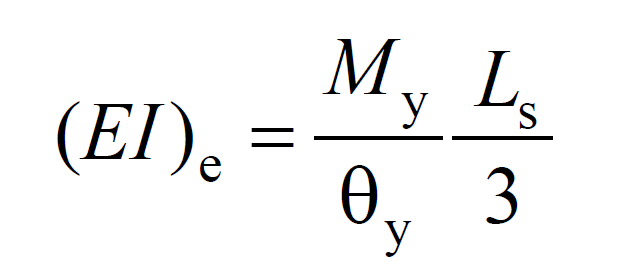
(EI)e = Effective section stiffness of column, beam, tie beam or wall modeled according to the stacked plastic behavior
Ls = Shear clearance [m]
My = Effective yield moment [kNm]
θy = Displaced axis rotation for yield state[rad]
The Piled Plastic Behavior Model is a behavior model created with the assumption that nonlinear bending deformations are concentrated in a small region called a plastic joint . The system is assumed to behave linear-elastic in regions outside the plastic hinge area. For this reason, reinforced concrete columns and beams with the length remaining between plastic hinges are modeled as linear elements. Since the plastic hinges are automatically placed in the carrier system , the analysis model of the columns and beams, which will act as linear elements for the remaining length, is automatically created.
The effective section stiffnesses of the linear elements (columns and beams) between the plastic hinges are determined by the formula below according to TBDY Section 5.4.5 . Effective section stiffnesses of columns and beams modeled as linear elements. It is explained in detail under the headingEffective Section Stiffness of Structural System Elements
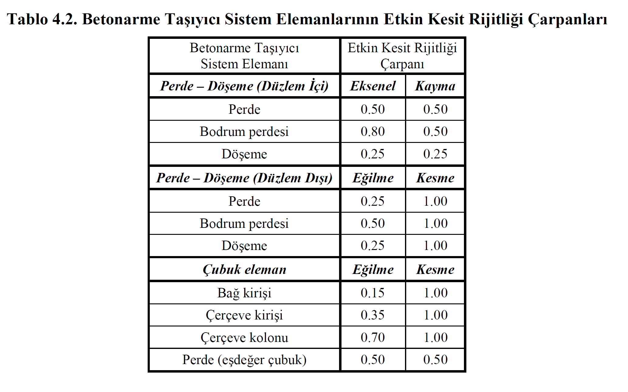
As a second option, the effective section stiffnesses of the linear elements (columns and beams) between the plastic hinges can be determined according to Table 4.2 specified in TBDY Section 4.5.8 . Effective section stiffnesses of columns and beams modeled as linear elements. It is explained in detail under the heading Effective Section Stiffness of Structural System Elements