-
Beam longitudinal reinforcements are placed automatically according to the internal forces of all reinforced concrete element design combinations and according to the longitudinal reinforcement conditions described in Section 7.4.2 of TBDY .
-
Minimum ratio of tensile reinforcement in the beam bearings Eq. (7.8) 'to be automatically controlled.
-
The condition that the diameter of longitudinal rebars cannot be selected less than 12 mm is automatically controlled.
-
The condition that the tensile reinforcement ratio in the spans and supports will not be more than the maximum value given in TS 500 and 2% is automatically controlled.
ICONS
DTS = Earthquake Design Class
f ctd = Design tensile strength of concrete
f yd = Design yield strength of longitudinal reinforcement
l b = Interlock length given for tensile reinforcement at TS 500
ρ = ratio of upper or lower tensile reinforcement in beam support
ϕ = Reinforcement diameter
In TBDY Section 7.4.2 , the conditions for beam longitudinal reinforcement are specified. These are listed below.
-
The minimum tensile reinforcement ratio in beam supports is specified in TBDY Equation (7.8) .

In this equation, ρ is the reinforcement ratio in the beam support, f ctd is the design tensile strength of the concrete, f yd is the yield strength of the reinforcement.
-
Beam longitudinal reinforcement should not be less than 12 mm in diameter.
-
In carrier systems with DTS = 1, 1a, 2, 2a, the lower reinforcement in the beam support is not less than 50% of the upper reinforcement.
-
The ratio of tensile reinforcement in spans and supports shall not be more than the maximum value given in TS 500 and 2%.
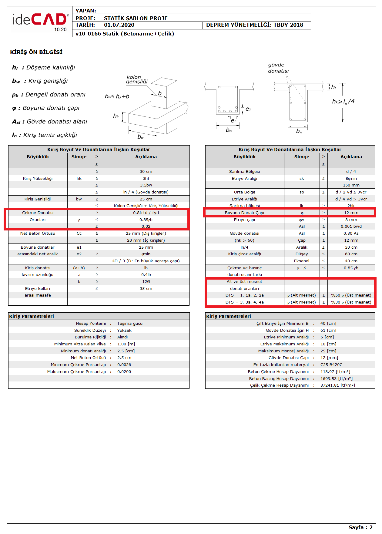
The above four conditions (7.4.2.1 , 7.4.2.2 , 7.4.2.3 and 7.4.2.4) specified in Section 7.4.2 of TBDY are specified in the Beam Preliminary Information report. The places where these four conditions exist are highlighted in red in the sample report image below.
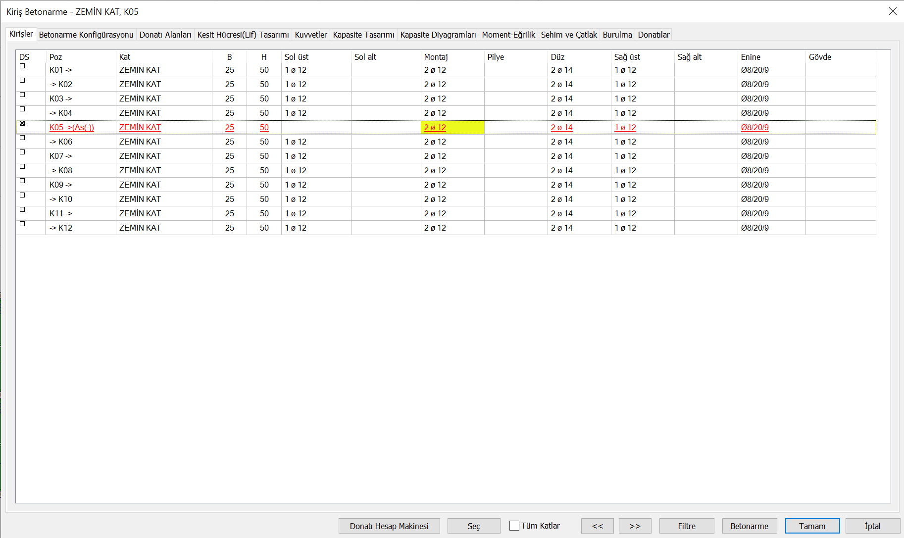
For beams, if the reinforcement required for internal forces calculated under the combined effect of vertical loads and earthquake loads and the minimum reinforcement conditions specified in TBDY Section 7.4.2 and TS 500 are not met, the insufficient reinforcement ratio error, As (-) is specified. In the image below, As (-) warning in the Beam Reinforced Concrete section is shown for a beam with sufficient reinforcement ratio .
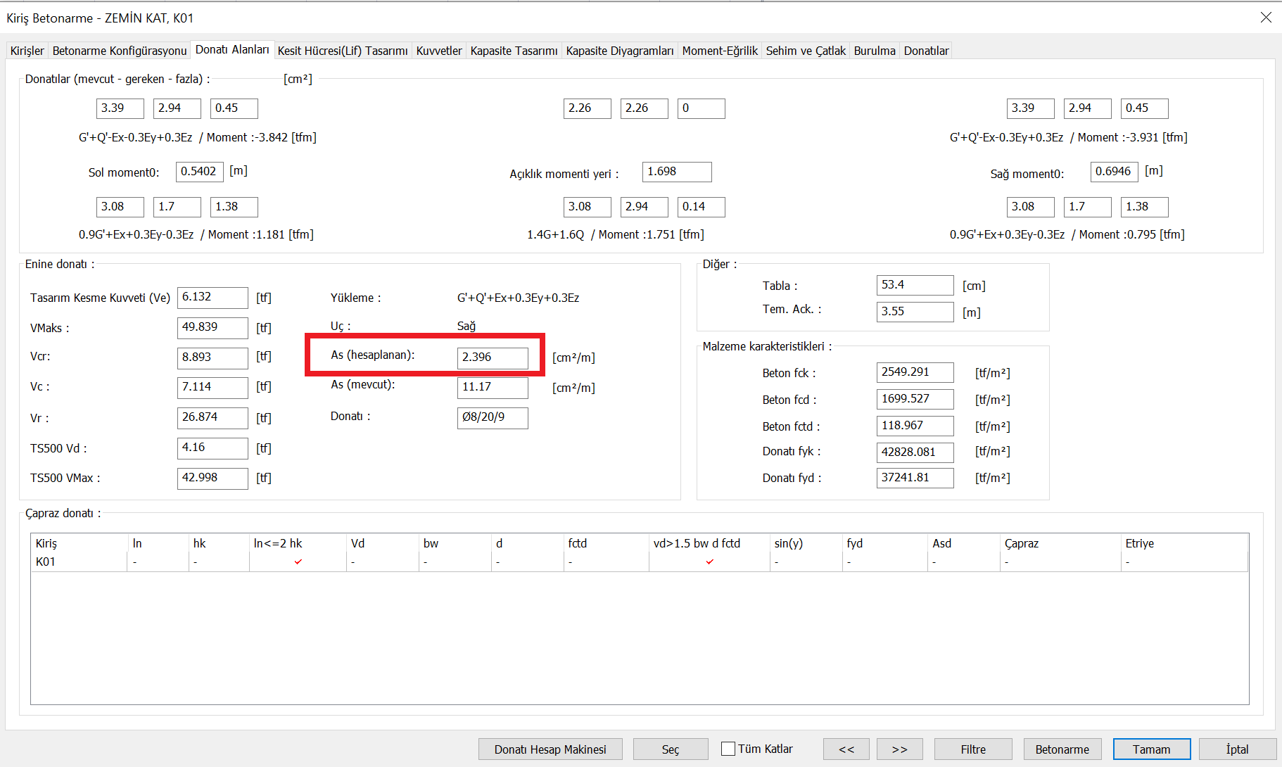
In the Reinforcement Areas tab of the Beam Reinforced Concrete section , the reinforcement required for the internal forces calculated under the joint effect of vertical loads and earthquake loads and the reinforcement area calculated by taking into account the minimum reinforcement conditions specified in TBDY Section 7.4.2 and TS 500 can be seen. In the image below, the area of reinforcement calculated in this way [As (calculated)] is shown in red.