
Moment Connection Design or Rigid Connection design is made automatically according to the Design, Calculation, and Construction Principles of Steel Structures and AISC 360-16 (ASD and LRFD) regulations. Bolt, weld, plate, geometry, and strength controls are done automatically following the steel connection type.
The Moment Connection in ideCAD Structural is a joint that transfers bending moment forces between a steel column and steel beam (or any other two steel members). If a child member (a steel beam) has some internal moment, the connection should be able to transmit the load due to that moment.
While The Shear Connections in ideCAD Structural depend mostly on the web of a section, moment connections add to that by strengthening the connectivity of the flanges. This can be achieved by using plate stiffeners, welds, or other fixtures that strengthen and increase the rigidity of the connection between members.
Download ideCAD for Connection Design with AISC 360-16
Moment connection types are listed below.
Moment Connection Design with ideCAD
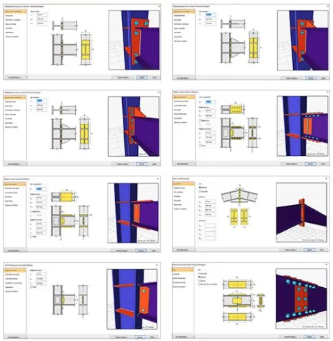
ideCAD Structural is an All-in-One Structural Engineering Software with Moment Connection and many other Integrated Building Information Modeling (BIM) tools.
Download ideCAD for Connection Design with AISC 360-16
Design Criteria for Moment Connections
-
Moment connections are classified as rigid and full/partial strength connections.
-
For rigid connections, end plate and welded connections are classified according to the rotational rigidity defined according to the earthquake regulations, depending on the ductility level.
Guideline for End Plate Connections
-
The strength of the end plate connection is determined by the assumption that the tensile force of the bolts on one part of the plate and the compressive forces of the bolts on the other are controlled by the bearing limit state.
-
If there is no axial load on the connection, the total tensile and compressive forces are equal and opposite in both parts, which creates a force pair.
-
To simplify the calculations, it is assumed that the center of rotation is in the center of the compression part.
Guideline for Splice Connection of Columns/Beams
-
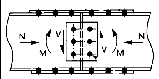
To suit the design under reversible forces such as earthquake forces, symmetrical and equal numbers of bolts are used on both flanges and webs. ideCAD does not allow asymmetrical connection during modeling.
-
It is assumed that the flanges carry the moment and the web carries the shear force, while the axial force is equally shared between both flanges.
-
The gap is left between the beam splices, while the column splices may or may not be left.
Guideline for Moment Connections with AISC 360-16
-
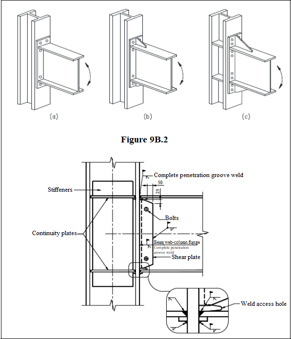
Depending on the ductility level, the connections must provide a relative translation angle of at least 0.04 or 0.02 radians according to the AISC 360-16. These connections are End Plate and Flange Plate connections designed in ideCAD Structural Steel.
-
If the design of the connections is preferred to be computed with AISC 360-16, the LRFD method is mandatory under the earthquake regulations.
-
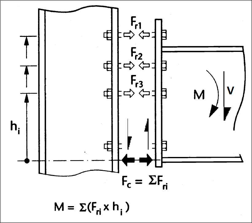
The required bending moment strength Muc and the required shear strength Vuc on the column face of the connections are calculated over the plastic hinges at the end of the beam. The formulas in the figure below are used.
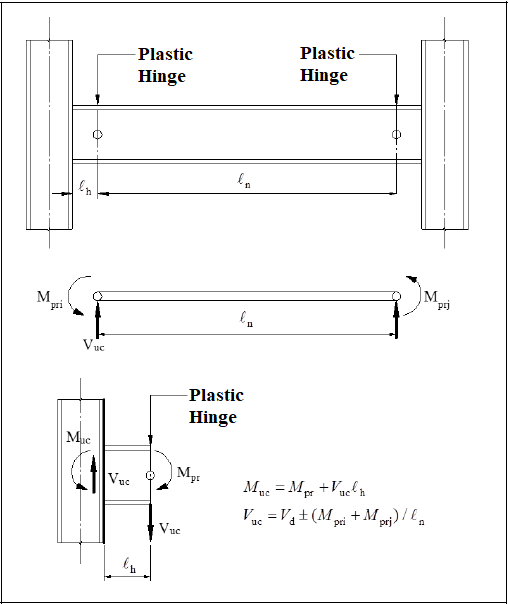
-
The Vuc used in the dimensioning of the connection is determined according to the equation in the figure above by summing the shear force determined based on the yielding limit state with the shear force calculated from the combination of 1.2G + 0.5Q + 0.2S on the plastic hinge at the end of the beam.
-
Plastic hinge length is specified separately for each connection in AISC 360-16, and automatic computation is made under these rules. Details will be given in each connection.
-
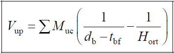
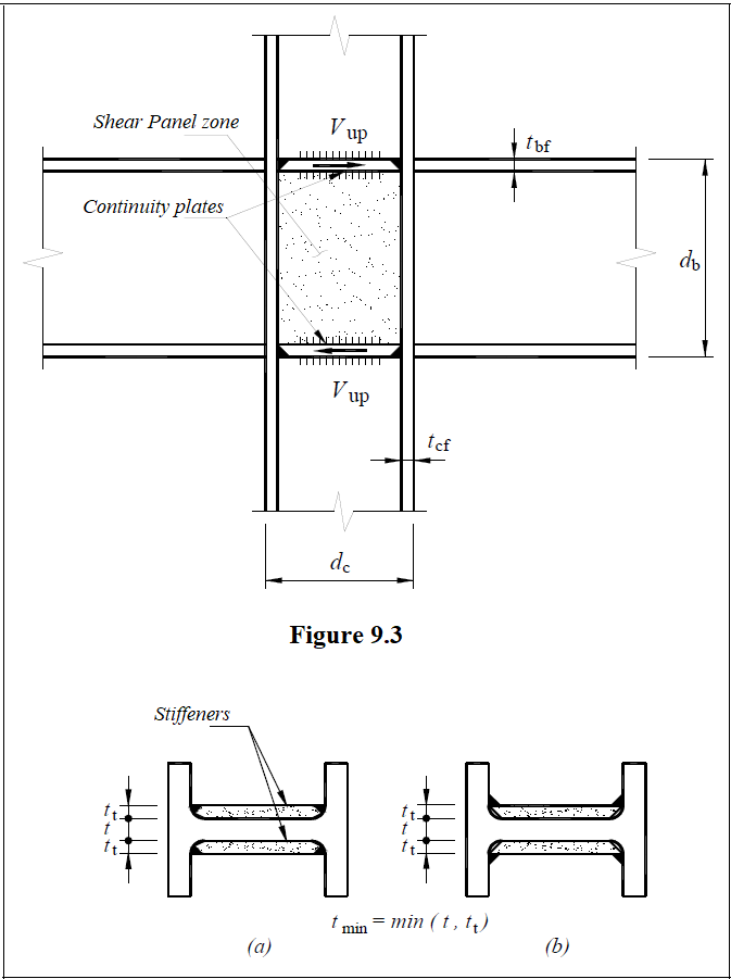
The shear strength required for the panel zone is calculated using the column shear force generated by the possible plastic moments of the beams connecting to the column.
Symbols
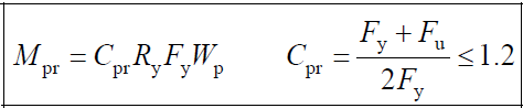
Cpr: This coefficient takes into account the strain-hardening, which is used to compute the maximum possible bending moment strength
Fu: Characteristic tensile strength of steel
Fy: Characteristic yield stress of steel
lh: The distance between the plastic hinge point at the beam end to the column face
ln: Beam span between plastic hinge points at the beam ends
Mpr: Possible bending moment strength
Mpri: Possible bending moment strength at the left end i of the beam
Mprj: Possible bending moment strength at the right end j of the beam
Muc: Required bending moment strength of the connection at the face of the column
Ry: The ratio of possible yield stress to the characteristic yield stress
Vd: Beam shear force computed from vertical loads at the plastic hinge point of the beam
Vuc: Required shear strength of the connection at the face of the column
Download ideCAD for Connection Design
Next Topic