15A.2
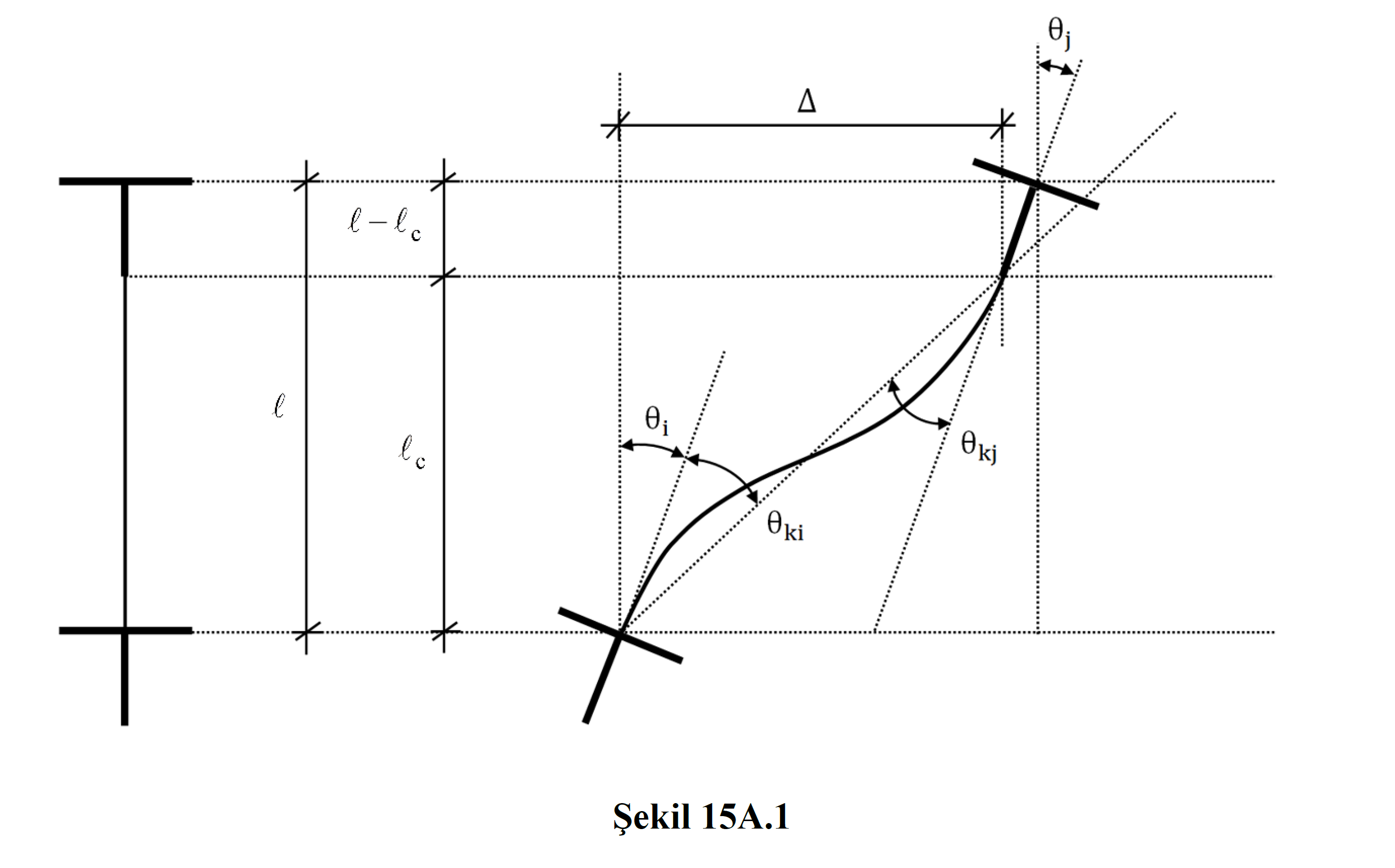
The displaced axis rotation values are used in linear performance analysis to calculate the strain and plastic rotation demands of columns, beams and shear elements.
Displaced axis rotation θ k is automatically calculated.
ICONS
I = Moment of inertia
L p = Plastic hinge length
l c = Element net span
R a = Earthquake Load Reduction Coefficient
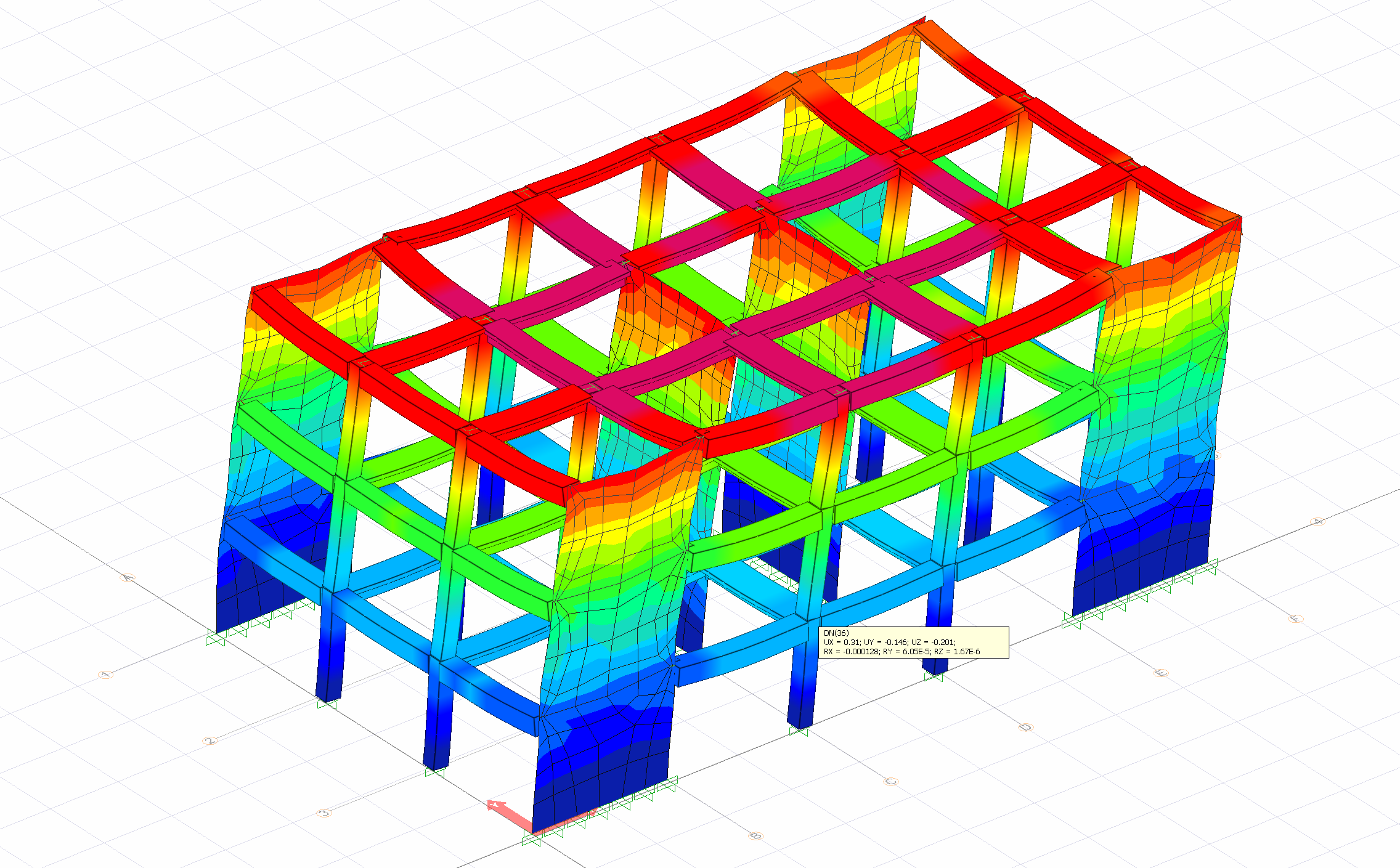
UX = The displacement of thejointpoint in the (X) direction in thethree-dimensional analysis model
UY = Thejointpoint in thethree-dimensional analysis model translation
UZ = Thetranslation ofthe node in the (Z) direction in thethree-dimensional analysis model
RX = The rotation of the joint point around the (X) axis in the three-dimensional analysis model
RY =Rotation of the
joint point about the (Y) axis in the three dimensional analysis model RZ = The rotation of the joint point around the (Z) axis in the three dimensional analysis model
Δ = The translation between the element nodes
ϕ y = Flow curvature
ϕ t = Total curvature
θ p = Plastic rotation lead
θ y = yield rotation
θ t = heat flow at the end of rotation
θ yj = return flow end j
θ k =Displaced axis rotation
θ ki = displaced axis rotation at end i
Evaluation and Design According to Strain existing buildings (ŞGDT) in determining the approach to seismic performance and linear calculation method used element plastic rotation demand θ p or elements curvature lead the end section φ t is calculated in line method.
Linear performance analysis is performed with the principle of "the total deformation value in an element is equal to the sum of the elastic deformations and the plastic deformations in that element". Plastic deformations for ductile reinforced concrete elements are rotational deformations due to the moment effect. According to this approach, in order to find the plastic deformation value of an element, the total deformation value of that element is found and then the elastic deformations are subtracted from this value.
I edge of an element of plastic rotation demand θ p is calculated from the following equation.

Similarly, the total curvature demand ϕ t of an element is calculated from the following equation.

Θ in this relation that represents the likelihood disposition rotational axis and Eq. (15A.1) 'is calculated from.

In this equation, the element represents the relative displacement between end nodes. l c is the element net opening. θ i value represents the rotation value of the element consisting of the vertical loads at joint i and earthquake loads ( loading cases ) taken as R a = 1 . In this case, ki can only be obtained from the analysis results made with linear earthquake calculation.

The translational value between floors in beam elements is taken as zero (= 0).
Since the building carrier system model is created in three dimensions, the relative ö value at the element nodes is also calculated in the three-dimensional system. The following picture shows the displacement results at any element node of a three-dimensional analysis system. In the analysis results , nodal displacement values consisting of vertical loads and earthquake loads ( loading cases ) taken as R a = 1 are used. These results are three translational values, UX, UY and UZ, and three rotation values, namely RX, RY and RZ. While calculating the value of, the vector displacements of UX and UY values of all column elements are taken into account. Similarly, the rotation value of a joint is ki When calculating, the vectoral rotations of the RX and RY rotation values are taken into account.

Next Topic
