
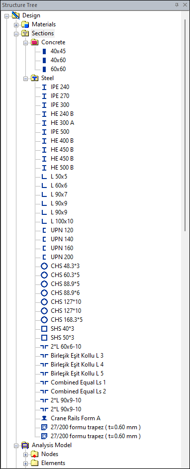
All sections used in the elements in the program are listed in the structure tree.
The sections for reinforced concrete elements are automatically defined from the given size values when the object is defined. For example, when a 40/60 column is defined, it is seen as a rectangular section in the Concrete Section list.
With Load Section From Library command defined sections can be added the Steel Section list.
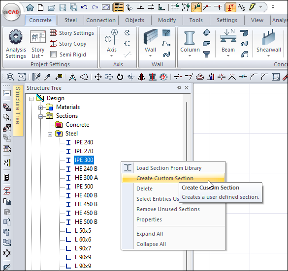
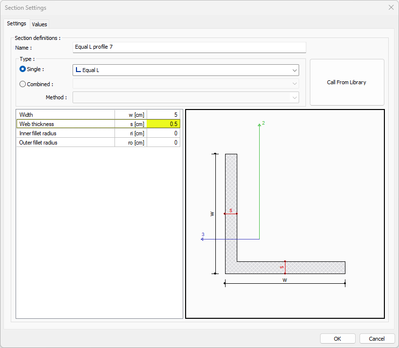
Also any steel section can be defined in the Steel Section list with the Create Custom Section command.
Section sizes used in the analysis for this section will be calculated manually by formulas and compared with the program.
Location of the Create Custom Section Command
You can access the command under the Structure Tree.
Manual Calculation of 40/60 Rectangular Section Sizes
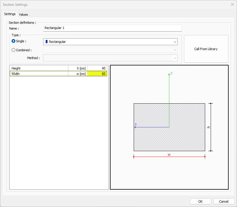
Values given by the program:

Manual control:
-
The second moment of inertia around the axis I 2 = HW 3 /12 = 40 * 60 3 /12 = 720000 cm4 (7.2 A + 5 cm4)
-
Moment of inertia around the 3 axis I 3 = w 3 d / 12 = 40 3 * 60/12 = 320000 cm4 (3.2E + 5 cm4)
-
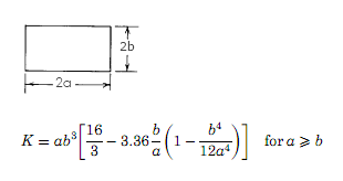
Torsion moment of inertia K = 30 * 20 3 [16/03 - 20/30 * * 3:36 (1-20 4 /12/30 4 ] = 751249.38 cm4 (7512 cm4 A + 5)
-
Cross-sectional area A = w. d = 40 * 60 = 2400 cm2
-
Cutting area in 2 direction = 5/6. b. w = 5/6 * 40 * 60 = 2000 cm2
-
Cutting area in 3 direction = 5/6. w. b = 5/6 * 40 * 60 = 2000 cm2
-
Radius of inertia in 2 axis = √I 2 / A = √720000 / 2400 = 17.32 cm2
-
Radius of inertia in 3 axis = √I 3 / A = √320000 / 2400 = 11.54 cm2
-
The strength of the elastic torque of the second axis = bh 2 /6 = 40 * 60 * 60/6 = 24000 cm3
-
Elastic strength moment in 3 axis = b 2 h / 6 = 40 * 40 * 60/6 = 16000 cm3
-
2 plastic structural strength axis torque = bh 2 /4 = 40 * 60 * 60/4 = 36000 cm3
-
Plastic strength moment in the 3 axis = b 2 h / 4 = 40 * 60 * 60/4 = 24000 cm3
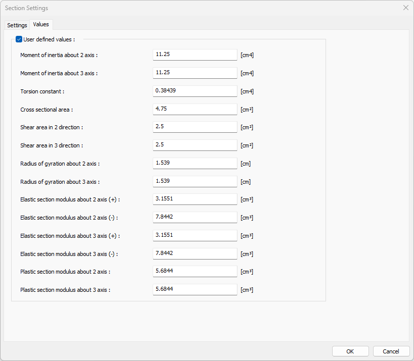
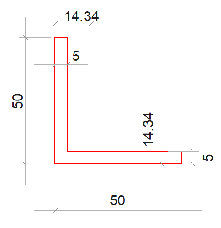
Manual Calculation of Sample L Profile Section Sizes
-
Location of the neutral axis
x1= (50*5*2.5 + 45*5*27.5) / (50*5+45*5) = 14.34 mm
y1= (50*5*25+45*5*2.5)/(50*5+45*5)=14.34 mm
-
With the parallel axis theorem, the 3-axis moment of inertia
yg1 = 25-14.34 = 10.16mm (distance of the parallel axis to the center of gravity)
yg2 = 14.34-2.5 = 11.84 mm (distance of the parallel axis to the center of gravity)
I3 =5*503/12+5*50*10.662 + 45*53/12+45*5*11.842 = 112502.74 mm4 → (1.125E+5mm4)
-
With the parallel axis theorem, the 2-axis moment of inertia
xg1 = 14.34-2.5 = 11.84mm (distance of the parallel axis to the center of gravity)
xg2 = 27.5-14.34 = 13.16 mm (distance of the parallel axis to the center of gravity)
I2 =53*50/12+5*50*11.842 + 453*5/12+45*5*13.162 = 112502.74 mm4 → (1.125E+5mm4)
-
Cross-sectional area
A= 5*50+45*5=475 mm4
-
Radius of inertia in the 2 axis = √112502.74 / 475 = 15.39 cm2
-
Radius of inertia in 3 axis = √112502.74 / 475 = 15.39 cm2
Next Topic