ICONS
α = Horizontal distance between stirrup arms and / or crossties in the curtain end zone
ϕ = Reinforcement diameter
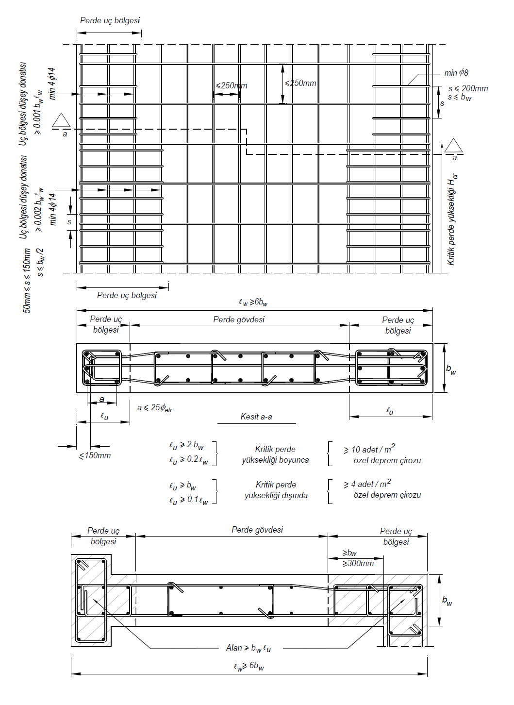
7.6.5. Reinforcement Conditions in Wall End Regions
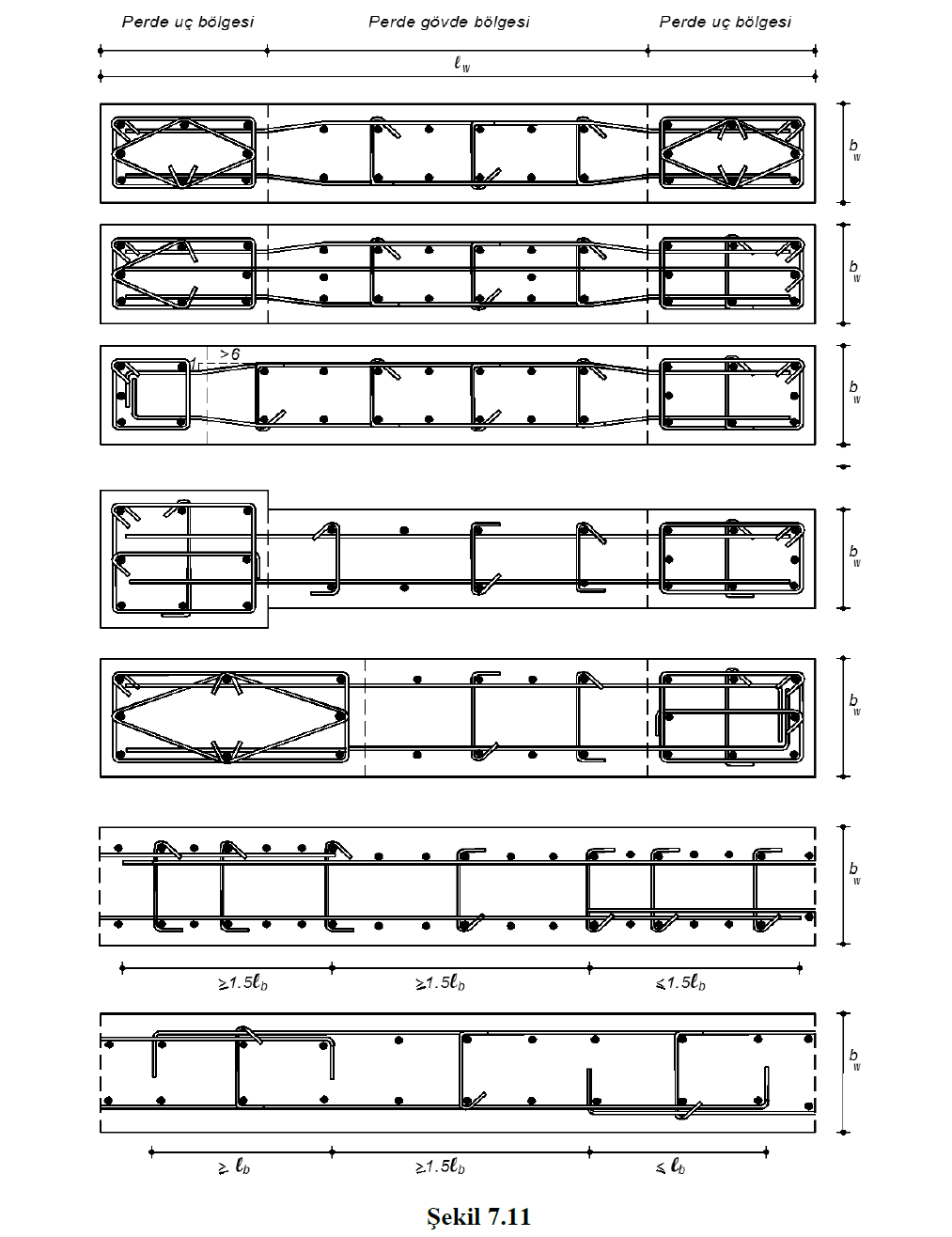
Along the critical wall height defined in 7.6.5.1 - 7.6.2.2 , the ratio of total vertical reinforcement area in each of the wall end zones will be at least 0.002. Apart from this height, this ratio will not be less than 0.001. The transition in geometry and reinforcement of the wall end zone will be made gradually over three floors. Also, the amount of longitudinal reinforcement in each of the wall end zones shall not be less than 4ϕ14. Longitudinal reinforcement ratio shall not exceed 0.03 (0.06 in overlap zone) in the wall end regions ( Figure 7.11 ).
7.6.5.2 - Vertical reinforcements at wall end zones will be wrapped with transverse reinforcements consisting of stirrups and / or crossties as in columns, in accordance with the rules in (a) , (b) and (c) below .
(a) The diameter of the transverse reinforcement to be used in the end regions shall not be taken less than 8 mm. The horizontal distance between the stirrup arms and / or crossties, α, shall not be more than 25 times the diameter of the stirrup and crotch.
(b) 7.6.2.2 as defined in the critical wall height of the wall end zones along, for winding zones of columns 7.3.4.1 from Eq. (7.1) "in the second condition of at least the determined transverse reinforcement 2/3 will be placed. In the vertical direction, the stirrup and / or cross-tie spacing shall not be taken as larger than 150 mm and smaller than 50 mm ( Figure 7.11 ). This gap will not be more than 6 times the longitudinal reinforcement diameter and 1/3 of the wall thickness. Transverse reinforcements in the wall end zone will be continued in the foundation along a height not less than 300 mm and wall thickness.
(c) In the wall end regions other than the critical wall height, the stirrup and / or tread spacing in vertical direction shall not be taken greater than 200 mm from the wall thickness ( Figure 7.11 ).