
Design Settings for Sub-Tabs
-
After the steel column modeling is completed, double click on the element to enter its properties.
-
3 new sub-tabs will appear in the steel column menu. These tabs contain adjustments for analysis and design.
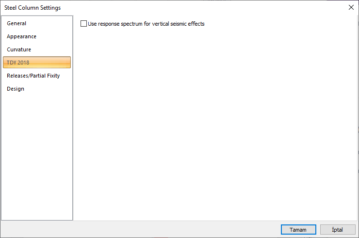
TDY 2018 Tab
|
Specifications |
|---|
|
Use response spectrum for vertical seismic effects If it is marked, the calculation is made with the vertical design spectrum in accordance with 4.4.3.1 and EdR (Z) is calculated for the calculation of the vertical earthquake effect. |
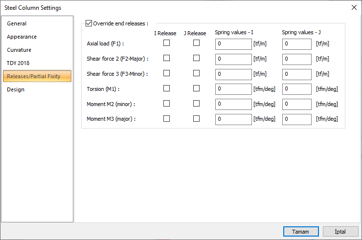
Releases/Partial Fixity Tab
|
Specifications |
|---|
|
Override end releases If it is marked, end releases and spring values that are entered at the start and end points of the element are become active. |
|
I release If the axial force for the starting point of the element 2-direction shear force, 3-direction shear force, torsion, 2-direction moment and 3-direction moment are indicated, the corresponding force will be 0 at the starting point. |
|
J release For the end point of the element, axial force, 2-direction shear force, 3-direction shear force, torsion, 2-direction moment and 3-direction moment are indicated, the corresponding force will be 0 at the starting end. |
|
Spring values - I 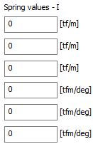
The spring coefficient is entered for the starting point of the element. Units can be changed by clicking the right button in the box. |
|
Spring values - J 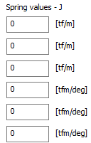
Spring coefficient is entered for the end point of the element. Units can be changed by clicking the right button in the box. |
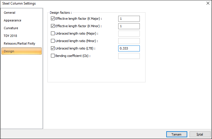
Design Tab
|
Specifications |
|---|
|
Effective length factor(K major) Effective length factor for major axis is given. |
|
Effective length factor(K minor) Effective length factor for minor axis is given. |
|
Unbraced length ratio (major) The ratio of the length between two elements connected to the element in its strong direction to the entire element length is given. |
|
Unbraced length ratio (minor) The ratio of the length between two elements connected in the weak direction to the entire element length is given. |
|
Unbraced length ratio (LTB) The ratio of the length between two elements connected to the element for the respective direction to the entire element length to be used in the lateral torsion buckling calculation is given. |
|
Bending coefficient (Cb) Lateral-torsional buckling modification factor for non-uniform moment diagrams when both ends of the member is supported. The moment correction coefficient is calculated according to the Steel Structures Regulation Equation 9.1. |
-
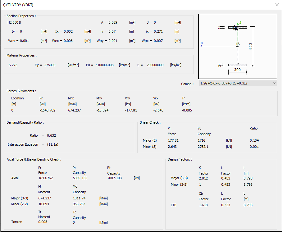
Control is given in the steel design - column - details section after analysis and design.
Next Topic