
SYMBOLS
Eh = Horizontal seismic load effect
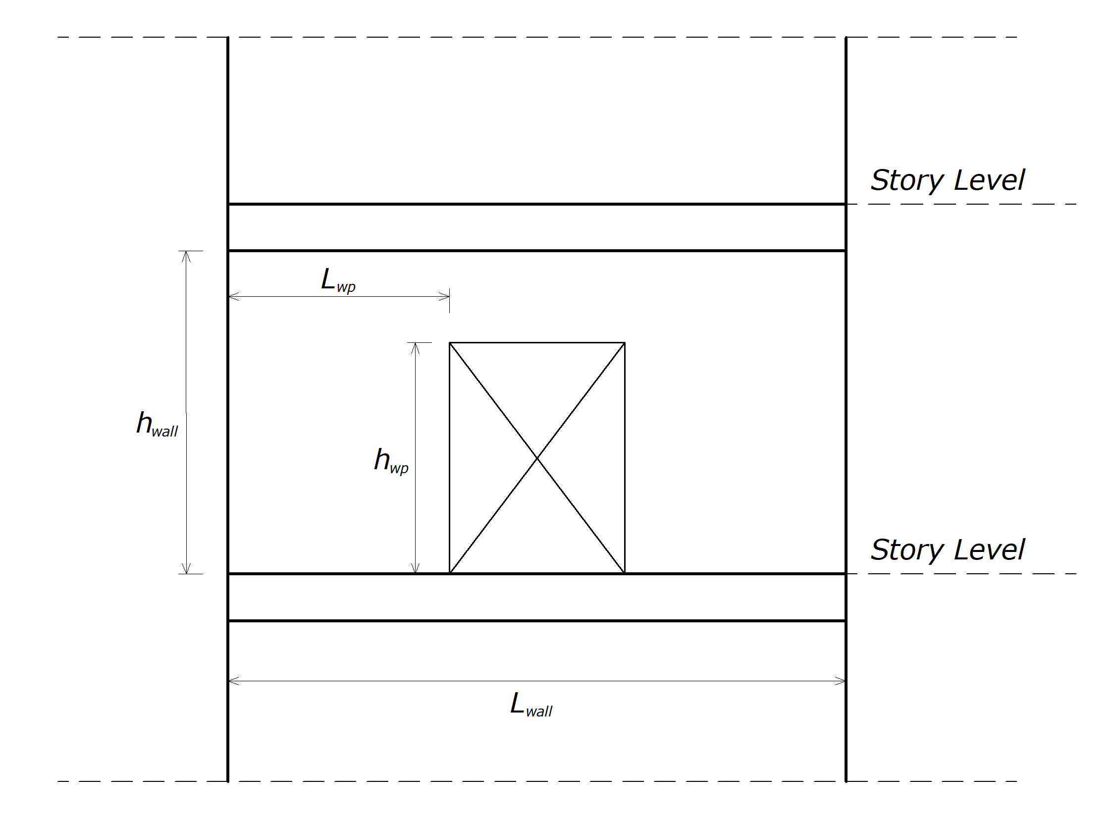
hwall = height of shear wall
hwp = height of wall pier
Lwall = length of shear wall
Lwp = length of wall pier
ρ = Redundancy factor
QE = Effects of horizontal seismic forces from V or Fp
The Redundancy factor, ρ, is used for the seismic force-resisting system in each of two orthogonal directions for all structures in accordance with Eq. 12.4-3.
'%3e%3cg transform='translate(167%2c0)'%3e%3cg transform='translate(-13%2c0)'%3e%3cg transform='translate(0%2c-25)'%3e%3cuse xlink:href='%23MJMATHI-45' x='0' y='0'%3e%3c/use%3e%3cuse transform='scale(0.707)' xlink:href='%23MJMATHI-68' x='1044' y='-213'%3e%3c/use%3e%3cuse xlink:href='%23MJMAIN-3D' x='1523' y='0'%3e%3c/use%3e%3cuse xlink:href='%23MJMATHI-3C1' x='2580' y='0'%3e%3c/use%3e%3cg transform='translate(3097%2c0)'%3e%3cuse xlink:href='%23MJMATHI-51' x='0' y='0'%3e%3c/use%3e%3cuse transform='scale(0.707)' xlink:href='%23MJMATHI-45' x='1119' y='-213'%3e%3c/use%3e%3c/g%3e%3cuse xlink:href='%23MJMAIN-28' x='9529' y='0'%3e%3c/use%3e%3cg transform='translate(9919%2c0)'%3e%3cuse xlink:href='%23MJMAIN-31'%3e%3c/use%3e%3cuse xlink:href='%23MJMAIN-32' x='500' y='0'%3e%3c/use%3e%3cuse xlink:href='%23MJMAIN-2E' x='1001' y='0'%3e%3c/use%3e%3cuse xlink:href='%23MJMAIN-34' x='1279' y='0'%3e%3c/use%3e%3c/g%3e%3cuse xlink:href='%23MJMAIN-2212' x='11921' y='0'%3e%3c/use%3e%3cuse xlink:href='%23MJMAIN-33' x='12922' y='0'%3e%3c/use%3e%3cuse xlink:href='%23MJMAIN-29' x='13422' y='0'%3e%3c/use%3e%3c/g%3e%3c/g%3e%3c/g%3e%3c/g%3e%3c/svg%3e)
According to 12.3.4.1 - ρ is 1.0 for the following:
-
Structures assigned to Seismic Design Category B or C
-
P-delta effects and story drift calculation
-
Design of collector elements, splices, and their connections using the seismic load effects with the overstrength factor of Section 12.4.3
-
Design of members or connections where the seismic load effects, including overstrength factor
-
Diaphragm loads determined using Eq. (12.10-1), including the limits imposed by Eqs. (12.10-2) and (12.10-3)
-
Structures with damping systems designed per ASCE Chapter 18
-
Design of structural walls for out-of-plane forces, including their anchorage
Redundancy Factor, ρ, for Seismic Design Categories D through F
For structures assigned to Seismic Design Category D with extreme torsional irregularity as defined in Table 12.3-1, Type 1b, ρ equals 1.3.
For other structures assigned to Seismic Design Category D and for structures assigned to Seismic Design Categories E or F, ρ is controlled automatically. Moreover, the software uses 1.3 unless one of the following conditions occurs.
Seismic Design Categories E and F are not allowed to use because extreme torsional irregularities are prohibited.
-
Each story resisting more than 35% of the base shear in the direction of interest according to Table 12.3-3.
-
Structures are regular in plan at all levels provided that the seismic force-resisting systems consist of at least two bays of seismic force-resisting perimeter framing on each side of the structure in each orthogonal direction at each story resisting more than 35% of the base shear.
|
Lateral Force-Resisting Element |
Requirement |
|---|---|
|
Braced frames |
Removal of an individual brace, or connection thereto, would not result in more than a 33% reduction in story strength, nor does the resulting system have an extreme torsional irregularity (horizontal structural irregularity Type 1b). |
|
Moment frames |
Loss of moment resistance at the beam-to-column connections at both ends of a single beam would not result in more than a 33% reduction in story strength; nor does the resulting system have an extreme torsional irregularity (horizontal structural irregularity Type 1b). |
|
Shear walls or wall piers with a height-to-length ratio greater than 1.0 |
Removal of a shear wall or wall pier with a height-to-length ratio greater than 1.0 within any story, or collector connections thereto, would not result in more than a 33% reduction in story strength; nor does the resulting system have an extreme torsional irregularity (horizontal structural irregularity Type 1b). The shear wall and wall pier height-to-length ratios are determined as shown in Figure. |
|
Cantilever columns |
Loss of moment resistance at the base connections of any single cantilever column would not result in more than a 33% reduction in story strength; nor does the resulting system have an extreme torsional irregularity (horizontal structural irregularity Type 1b). |
|
Other |
No requirements. |
Next Topic
Related Topics
-
Response Modification Coefficient for Modal Analysis per ASCE 7-16 with ideCAD
-
Reduced Design Response Spectrum for Modal Analysis per ASCE 7-16 §12.9.1.2
-
The Direction Combination of Horizontal Seismic Load Effect per ASCE 7-16 with ideCAD
-
Combining Horizontal and Vertical Earthquake Effects per ASCE 7-16 with ideCAD