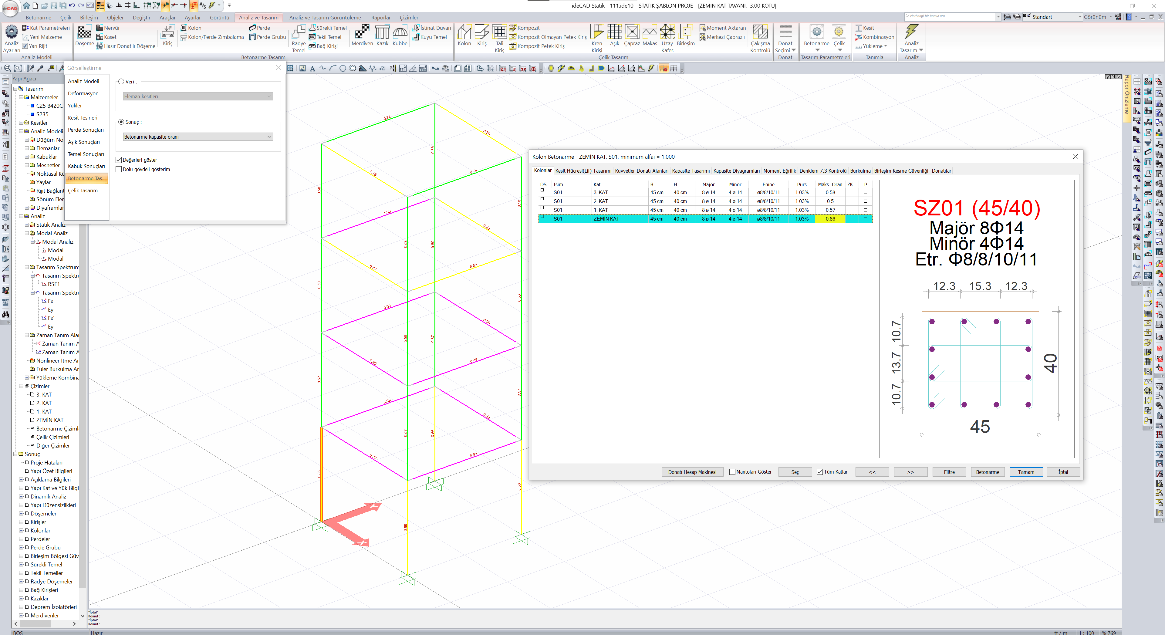
The maximum ratio represents the largest capacity ratio of the shear wall under the effect of axial force and biaxial bending, from the calculated capacity ratios in the existing reinforcement layout and under the effect of all combinations. If this value is greater than 1, it is an indication of inadequacy, which indicates that the element capacity is out of the interaction curve under the influence of axial force and biaxial bending moments.
Statistically required purchase and maximum capacity ratio are related terms. Statistically required pursantage is the ratio of reinforcement required to meet the most unfavorable condition of the element under the influence of axial force and biaxial bending. The maximum ratio, on the other hand, expresses the highest capacity ratio of the column under the effect of axial force and biaxial bending, from the capacity ratios calculated under the effect of all combinations and in the existing reinforcement placement.
The terms Vd, Ve, Vr, Vemax are explained below, respectively.
Vd: is the shear force calculated under the combined effect of vertical loads and earthquake loads. When calculating this shear force, the shear force on the arm of each curtain group is taken into account.
Ve: design shear force calculated according to TBDY 7.6.6 ,
For walls satisfying the condition H w / l w > 2.0, the design shear force, V e , to be taken as a basis in the calculation of the transverse reinforcement at any cross-section considered , shall be calculated by Eq.(7.16) .
In cases where a more precise calculation is not made, (M p ) t ≤1.25 (M r ) t can be accepted. The value obtained by increasing the vertical loads and the shear force calculated from the earthquake according to Chapter 4 by a multiple of 1.2D (gapless shear walls) or 1.4D (bond beam shears), Eq. If Ve is less than Ve calculated by (7.16) , this shear force will be used instead of Ve. In all sections of walls with H w / l w ≤ 2.0, the design shear forces shall be taken equal to the shear forces calculated according to Section 4 .
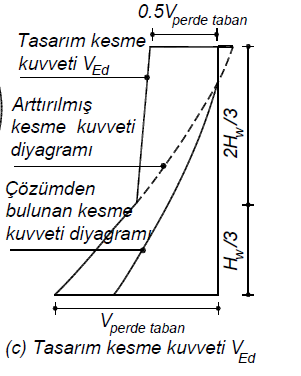
TBDY Figure 7.12(c) shows the wall design shear force graph. The design shear force at the top of the wall shall be taken as half of the design shear force at the bottom of the wall. For the part larger than H w /3, the shear force at the H w / 3 point and the shear force taken as half of the wall base at the top of the wall will be combined with a linear line to form a design shear force diagram.
V r : denotes shear strength. Shear strength is calculated by TBDY Equation 7.17 .
While calculating the shear strength Vr , the contribution of the header transverse reinforcements is also taken into account.
Ve Max : It is the maximum shear strength that the curtain can take, calculated according to TBDY Equation 7.18 .
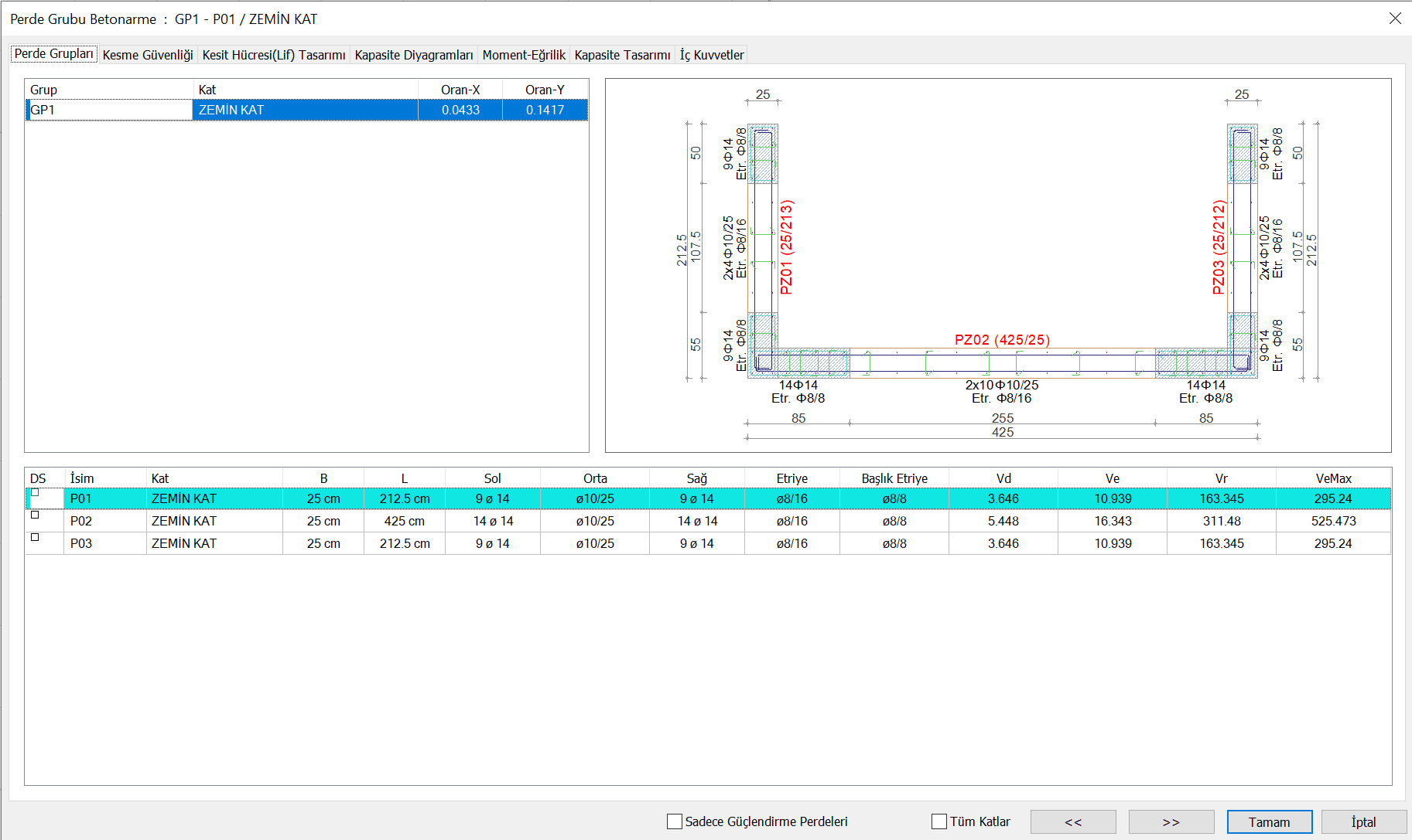
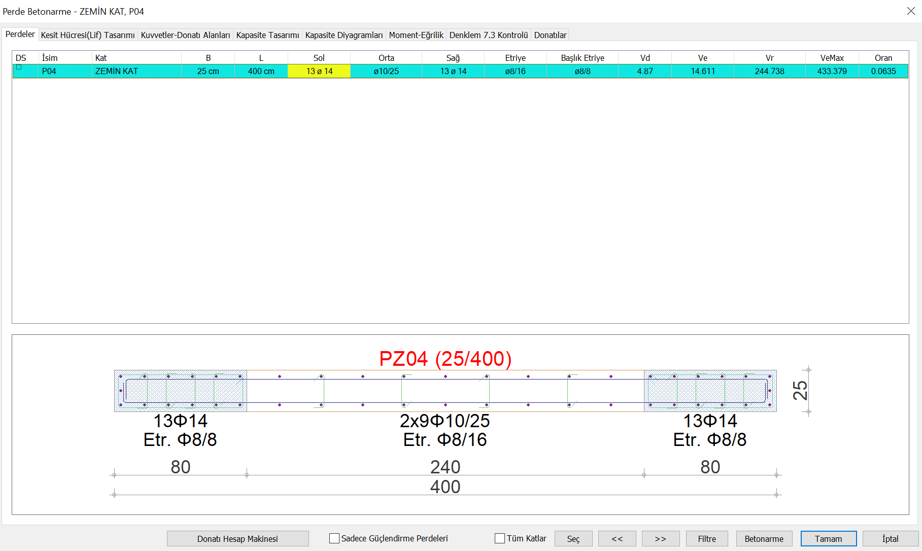
Max . _ The ratio value is shown below.