
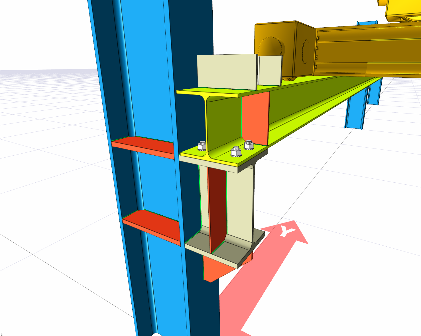
With the Crane Connection command, column-crane beam connection is defined.
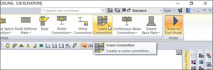
Location of the Crane Connection Command
You can access it under the Ribbon menu, Connection tab, Experimentals title.
Usage Steps
After drawing your crane between the columns;
-
Click the Crane Connection row from the Connection menu.
-
Select the main element (column).
-
Choose the crane beams.
-
The connection will occur with default settings.
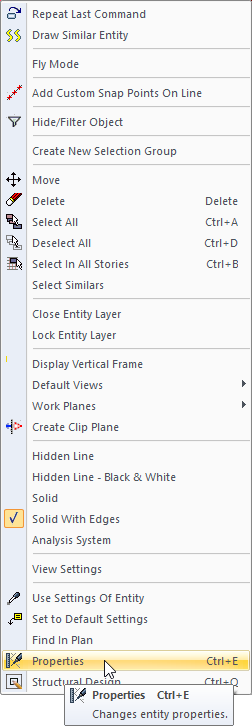
Location of the Crane Connection Dialog
Select the connection and click the right mouse button. Click the Properties line from the right click menu that opens.
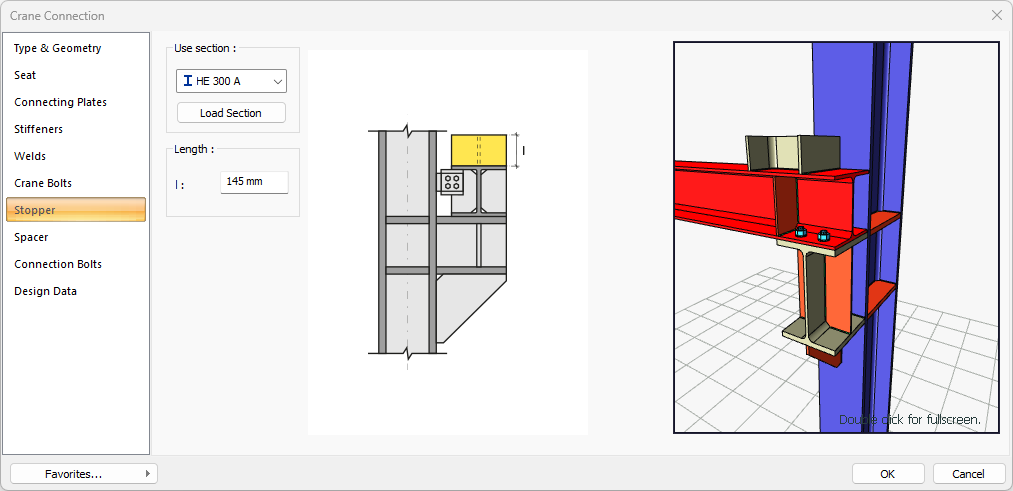
Crane Connection Dialog
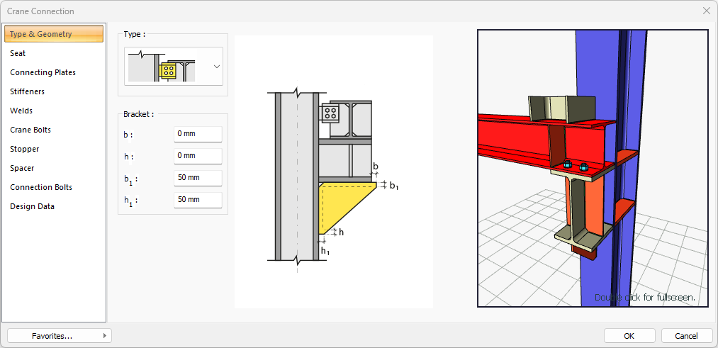
Type and Geometry Tab
|
Specifications |
|---|
|
Type 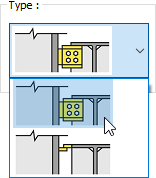
One of the connection types is selected from the list. |
|
Bracket 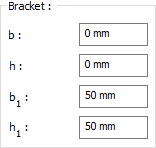
It is determined by entering the bracket values. The values to be entered are shown in the schematic drawing. |
|
Schematic drawing 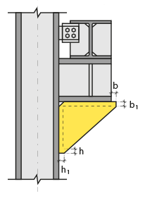
Connection and plate values are shown on the schematic drawing. |
|
Preview 
There is a preview of the connection. The selection made and the entered values can be followed simultaneously in the preview. |
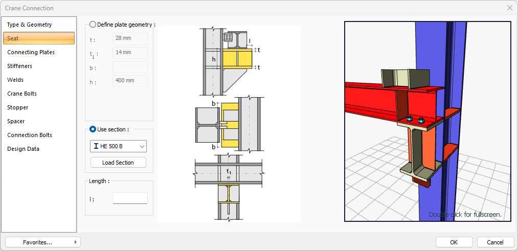
Seat Tab
|
Specifications |
|---|
|
Define plate geometry 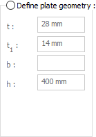
If the option is selected, it is determined by entering the angle values. The values to be entered are shown in the schematic drawing. |
|
Use section 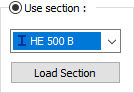
One of the ready profiles is selected from the list by checking the option. By clicking on the Load section button, you can reach the ready section library and reach the list of American and European finished rolling sections and select from the list. |
|
Length 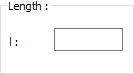
Profile length value is entered. |
|
Schematic drawing 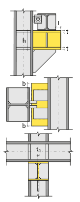
Connection and plate values are shown on the schematic drawing. |
|
Preview 
There is a preview of the connection. The selection made and the entered values can be followed simultaneously in the preview. |
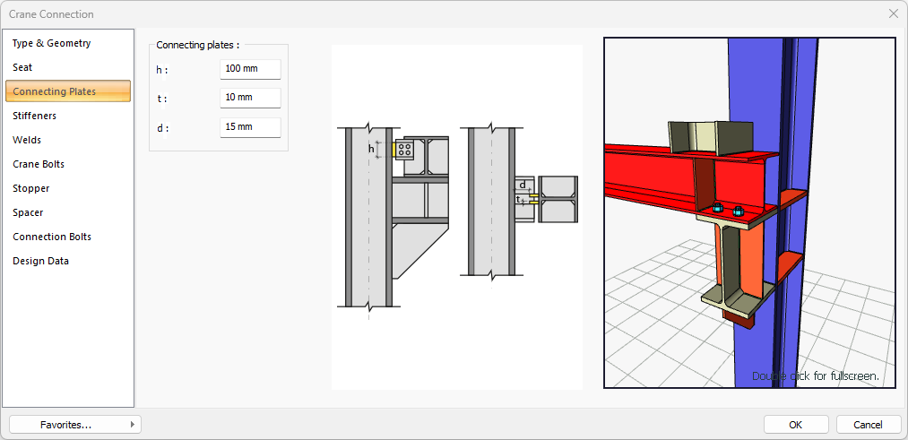
Connecting Plates Tab
|
Specifications |
|---|
|
Connecting plates 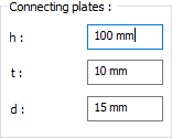
Connecting plates are determined by entering values. The values to be entered are shown in the schematic drawing. |
|
Schematic drawing 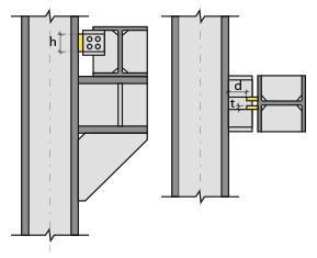
Connection and placement values are shown on the schematic drawing. |
|
Preview 
There is a preview of the connection. The selection made and the entered values can be followed simultaneously in the preview. |
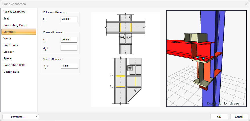
Stiffeners Tab
|
Specifications |
|---|
|
Column stiffeners 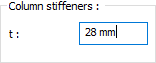
Column stiffeners are determined by entering the values. The values to be entered are shown in the schematic drawing. |
|
Crane stiffeners 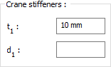
Crane stiffeners are determined by entering the values. The values to be entered are shown in the schematic drawing. |
|
Seat stiffeners 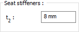
Seat stiffeners are determined by entering the values. The values to be entered are shown in the schematic drawing. |
|
Schematic drawing 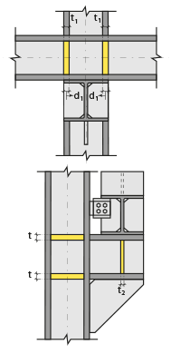
Connection and plate values are shown on the schematic drawing. |
|
Preview 
There is a preview of the connection. The selection made and the entered values can be followed simultaneously in the preview. |
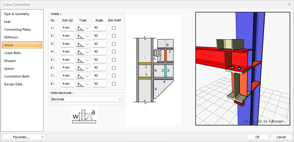
Welds Tab
|
Specifications |
|---|
|
Welds 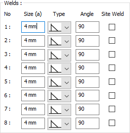
The thickness, type and angle values of the welds to be made at the connections are given. The information on whether it will be done on the construction site or not is entered. |
|
Weld electrode The strengths of the welding electrodes are defined in the design inputs. The strength of the main element in the weld joint is controlled under the condition that it has less strength than the weld strength. If necessary, click the list and define "Create New…". To create the welding electrode, give the information "Name" and "Weld metal tensile strength" in the dialog that opens after clicking "Create New". Welding geometry is determined automatically by the program. These properties can be changed to easily determine the connection properties. Geometry features are in accordance with industry standards and in the form specified in AISC. |
|
Schematic drawing 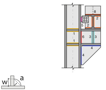
Connection and weld values are shown on the schematic drawing. |
|
Preview 
There is a preview of the connection. The selection made and the entered values can be followed simultaneously in the preview. |
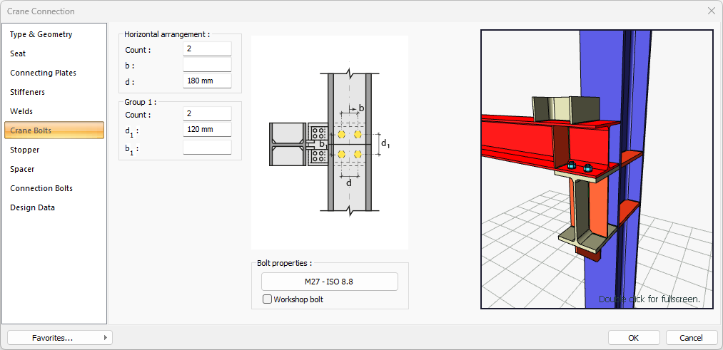
Crane Bolts Tab
|
Specifications |
|---|
|
Horizontal arrangement 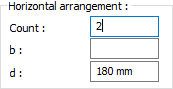
The horizontal arrangement distance value of the bolts is entered. The values to be entered are shown in the schematic drawing. |
|
Group 1 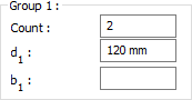
Distance values of bolts to beam and other bolts are entered. The values to be entered are shown in the schematic drawing. |
|
Bolt properties 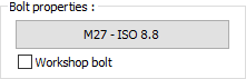
The Hole and Bolt Parameters dialog is opened by clicking on the bolt properties button. The bolt properties are set in this dialog. |
|
Schematic drawing 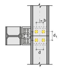
Connection and bolt placement values are shown on the schematic drawing. |
|
Preview 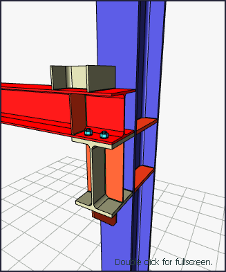
There is a preview of the connection. The selection made and the entered values can be followed simultaneously in the preview. |
Stopper Tab
|
Specifications |
|---|
|
Use section 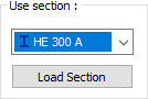
By checking the option, one of the ready profiles is selected from the list as a plug. By clicking on the Load section button, you can reach the ready section library and reach the list of American and European finished rolling sections and select from the list. |
|
Length 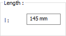
The length value is entered for the plug. |
|
Schematic drawing 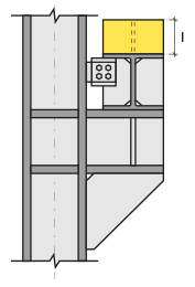
Connection and plate values are shown on the schematic drawing. |
|
Preview 
There is a preview of the connection. The selection made and the entered values can be followed simultaneously in the preview. |
Spacer Tab

|
Specifications |
|---|
|
Use section 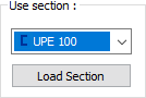
By checking the option, one of the ready profiles is selected from the list as a stamp. By clicking on the Load section button, you can reach the ready section library and reach the list of American and European finished rolling sections and select from the list. |
|
Length 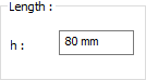
The length value is entered for the stamp. |
|
Schematic drawing 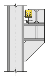
Connection and plate values are shown on the schematic drawing. |
|
Preview 
There is a preview of the connection. The selection made and the entered values can be followed simultaneously in the preview. |
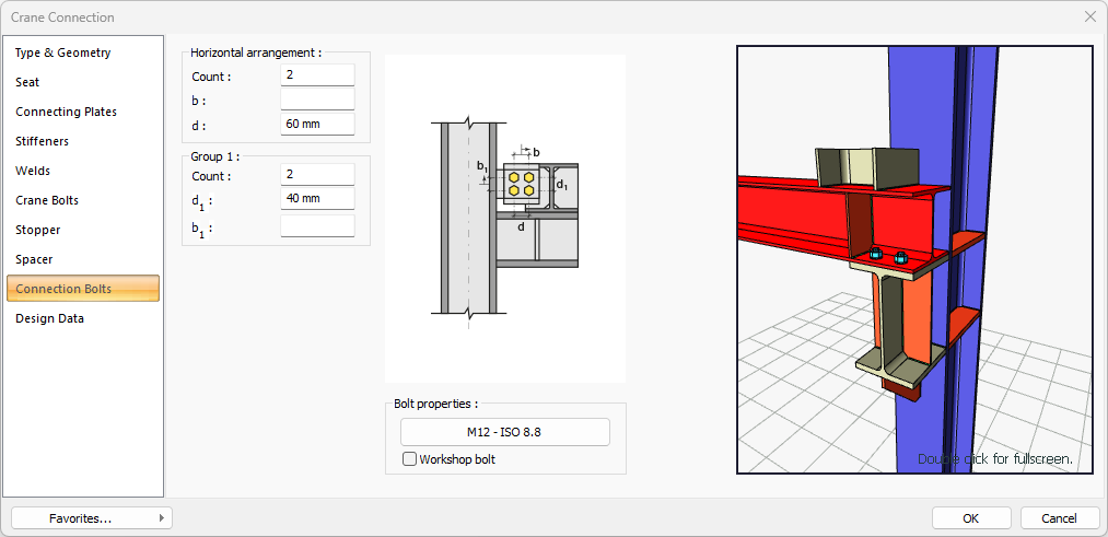
Connection Bolts Tab
|
Specifications |
|---|
|
Horizontal arrangement 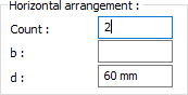
The horizontal arrangement distance value of the bolts is entered. The values to be entered are shown in the schematic drawing. |
|
Group 1 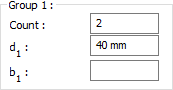
Distance values of bolts to beam and other bolts are entered. The values to be entered are shown in the schematic drawing. |
|
Bolt properties 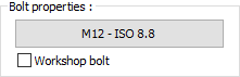
The Hole and Bolt Parameters dialog is opened by clicking on the bolt properties button. The bolt properties are set in this dialog. |
|
Schematic drawing 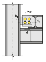
Connectionand bolt placement values are shown on the schematic drawing. |
|
Preview 
There is a preview of the connection. The selection made and the entered values can be followed simultaneously in the preview. |
Design Data Tab
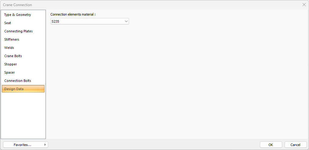
In the design data, the connection elements material is defined. The condition that the main element in the weld joint has less strength than the weld strength is controlled.
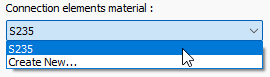
If necessary, click the list and define "Create New…". To create the connection elements material, give the information material definitions and values in the dialog that opens after clicking "Create New".
Next Topic
Related Topics