
Isometric, plan and elevation drawings of the scaffolding that modeled with ideCAD are prepared. If the scaffolding model is flanged, the flange details will be given in the drawing.
Location of the Scaffolding Drawing Command
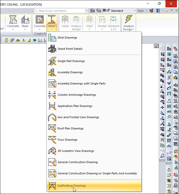
You can access it under the Steel tab, Create Drawings heading.
Usage Steps
-
Click the Scaffolding Drawing icon.
-
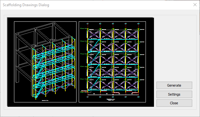
Scaffolding Drawing Dialog will open.
-
In the drawing properties dialog that opens when you click the Settings button, you can make the desired edits and click the OK button.
-
Click the Create button to create your scaffolding drawings.
|
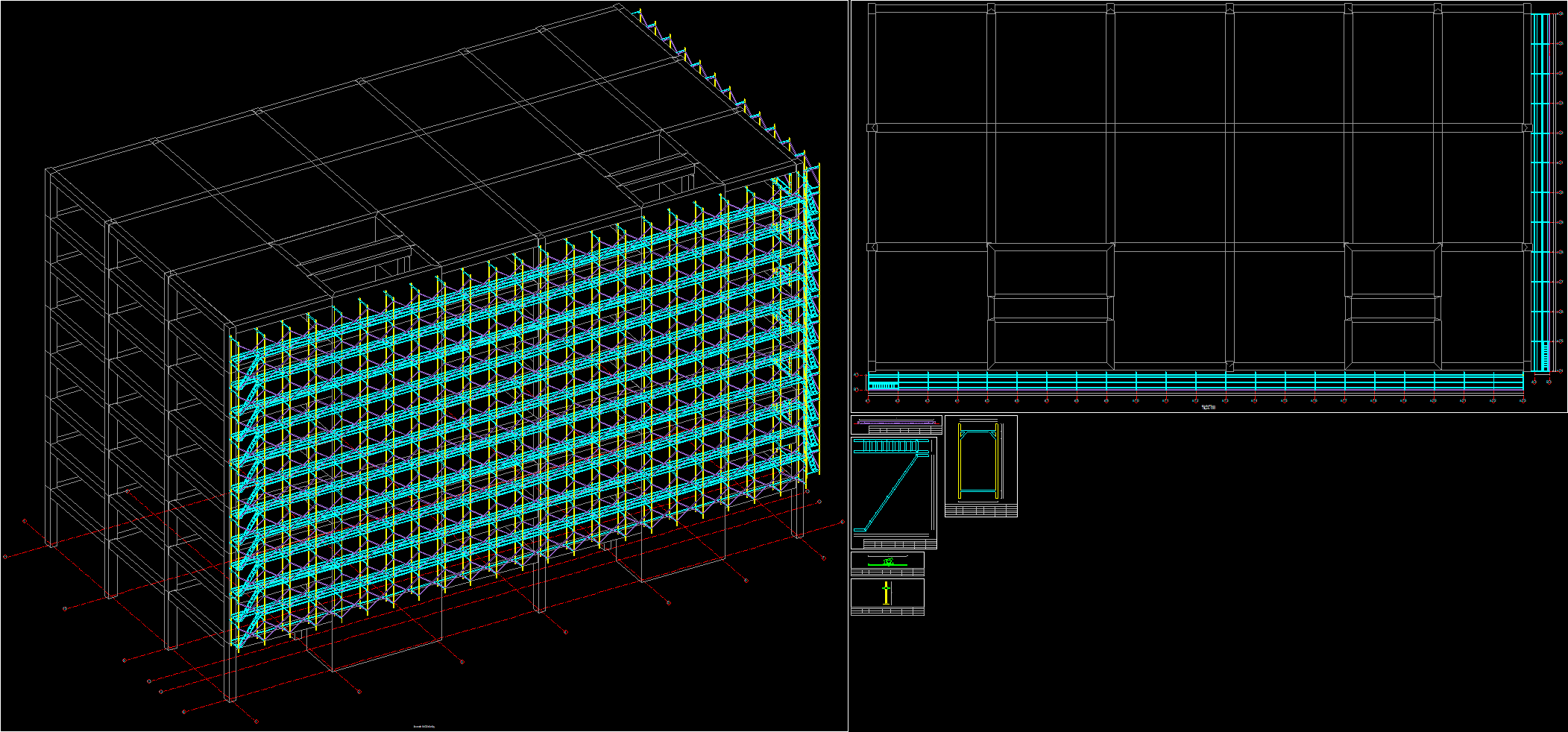
Sample scaffolding drawing |
|---|
|
Scaffolding Drawing Dialog
|
Specifications |
|
Scaffolding schematic drawing 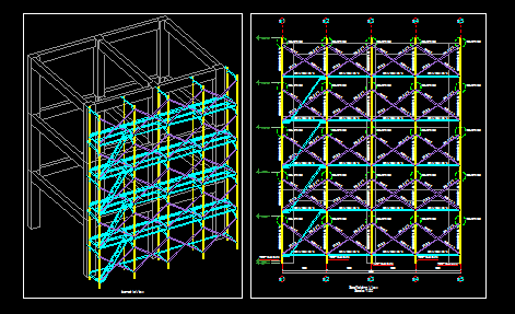
Schematic scaffolding drawing is shown. |
|
Generate Scaffolding drawings are generated. |
|
Settings Opens the steel drawing settings dialog for the scaffolding drawings. |
|
Close The scaffolding drawing dialog is closed by clicking the button. |
Settings
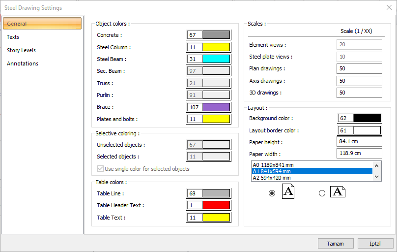
You can find detailed information about the settings in Steel Drawing Settings.
Next Topic