
Punching Shear Design Example
In the example calculation, a punching calculation will be made for a column whose dimensions are 100x80. Other parameters in the calculation are listed as follows.
-
Slab thickness: 27 cm
-
Slab cover: 3 cm
-
Material : C35/S420
-
fctd = 1380.42 kN/m2 (Concrete design tensile strength)
Download ideCAD for ACI 318-19 with Punching Shear Check
The slab useful height, d , is calculated;
d = ( Slab thickness - Slab cover ) = 27 - 3 = 24 cm
Column dimensions
c1 = 100 cm c2 = 80 cm
The punching circumference (up) is calculated at a distance d/2 from the column surface and is shown in the picture below. In this case, punching is done by adding d to the column dimensions to find the perimeter's edges (b1, b2).
'%3e%3cg transform='translate(167%2c0)'%3e%3cg transform='translate(-13%2c0)'%3e%3cg transform='translate(0%2c650)'%3e%3cuse xlink:href='%23MJMATHI-62' x='0' y='0'%3e%3c/use%3e%3cuse transform='scale(0.707)' xlink:href='%23MJMAIN-31' x='607' y='-213'%3e%3c/use%3e%3cuse xlink:href='%23MJMAIN-3D' x='1161' y='0'%3e%3c/use%3e%3cg transform='translate(2217%2c0)'%3e%3cuse xlink:href='%23MJMATHI-63' x='0' y='0'%3e%3c/use%3e%3cuse transform='scale(0.707)' xlink:href='%23MJMAIN-31' x='613' y='-213'%3e%3c/use%3e%3c/g%3e%3cuse xlink:href='%23MJMAIN-2B' x='3327' y='0'%3e%3c/use%3e%3cuse xlink:href='%23MJMATHI-64' x='4327' y='0'%3e%3c/use%3e%3cuse xlink:href='%23MJMAIN-3D' x='5129' y='0'%3e%3c/use%3e%3cg transform='translate(6185%2c0)'%3e%3cuse xlink:href='%23MJMAIN-31'%3e%3c/use%3e%3cuse xlink:href='%23MJMAIN-30' x='500' y='0'%3e%3c/use%3e%3cuse xlink:href='%23MJMAIN-30' x='1001' y='0'%3e%3c/use%3e%3c/g%3e%3cuse xlink:href='%23MJMAIN-2B' x='7909' y='0'%3e%3c/use%3e%3cg transform='translate(8909%2c0)'%3e%3cuse xlink:href='%23MJMAIN-32'%3e%3c/use%3e%3cuse xlink:href='%23MJMAIN-34' x='500' y='0'%3e%3c/use%3e%3c/g%3e%3cuse xlink:href='%23MJMAIN-3D' x='10188' y='0'%3e%3c/use%3e%3cg transform='translate(11244%2c0)'%3e%3cuse xlink:href='%23MJMAIN-31'%3e%3c/use%3e%3cuse xlink:href='%23MJMAIN-32' x='500' y='0'%3e%3c/use%3e%3cuse xlink:href='%23MJMAIN-34' x='1001' y='0'%3e%3c/use%3e%3c/g%3e%3cuse xlink:href='%23MJMATHI-63' x='13024' y='0'%3e%3c/use%3e%3cuse xlink:href='%23MJMATHI-6D' x='13457' y='0'%3e%3c/use%3e%3c/g%3e%3cg transform='translate(0%2c-750)'%3e%3cuse xlink:href='%23MJMATHI-62' x='0' y='0'%3e%3c/use%3e%3cuse transform='scale(0.707)' xlink:href='%23MJMAIN-32' x='607' y='-213'%3e%3c/use%3e%3cuse xlink:href='%23MJMAIN-3D' x='1161' y='0'%3e%3c/use%3e%3cg transform='translate(2217%2c0)'%3e%3cuse xlink:href='%23MJMATHI-63' x='0' y='0'%3e%3c/use%3e%3cuse transform='scale(0.707)' xlink:href='%23MJMAIN-32' x='613' y='-213'%3e%3c/use%3e%3c/g%3e%3cuse xlink:href='%23MJMAIN-2B' x='3327' y='0'%3e%3c/use%3e%3cuse xlink:href='%23MJMATHI-64' x='4327' y='0'%3e%3c/use%3e%3cuse xlink:href='%23MJMAIN-3D' x='5129' y='0'%3e%3c/use%3e%3cg transform='translate(6185%2c0)'%3e%3cuse xlink:href='%23MJMAIN-38'%3e%3c/use%3e%3cuse xlink:href='%23MJMAIN-30' x='500' y='0'%3e%3c/use%3e%3c/g%3e%3cuse xlink:href='%23MJMAIN-2B' x='7408' y='0'%3e%3c/use%3e%3cg transform='translate(8409%2c0)'%3e%3cuse xlink:href='%23MJMAIN-32'%3e%3c/use%3e%3cuse xlink:href='%23MJMAIN-34' x='500' y='0'%3e%3c/use%3e%3c/g%3e%3cuse xlink:href='%23MJMAIN-3D' x='9688' y='0'%3e%3c/use%3e%3cg transform='translate(10744%2c0)'%3e%3cuse xlink:href='%23MJMAIN-31'%3e%3c/use%3e%3cuse xlink:href='%23MJMAIN-30' x='500' y='0'%3e%3c/use%3e%3cuse xlink:href='%23MJMAIN-34' x='1001' y='0'%3e%3c/use%3e%3c/g%3e%3cuse xlink:href='%23MJMATHI-63' x='12523' y='0'%3e%3c/use%3e%3cuse xlink:href='%23MJMATHI-6D' x='12957' y='0'%3e%3c/use%3e%3c/g%3e%3c/g%3e%3c/g%3e%3c/g%3e%3c/svg%3e)
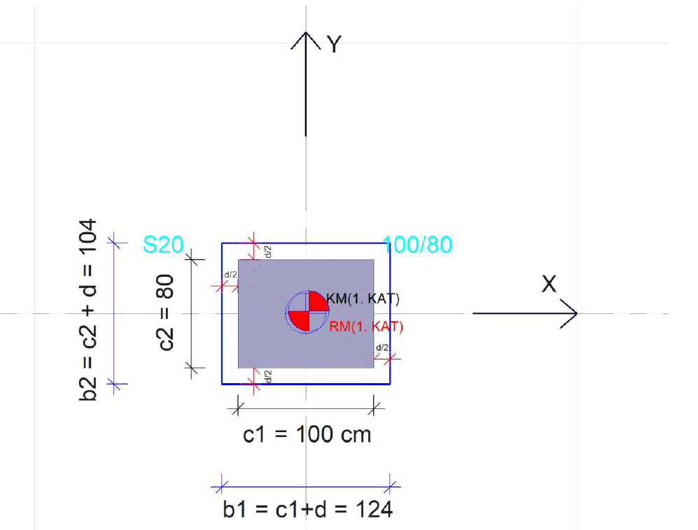
In this case, the punching circumference (up ) and the punching area (Az) obtained by multiplying the punching perimeter by the flooring useful height, d, is calculated as shown below.
'%3e%3cg transform='translate(167%2c0)'%3e%3cg transform='translate(-13%2c0)'%3e%3cg transform='translate(0%2c737)'%3e%3cuse xlink:href='%23MJMATHI-75' x='0' y='0'%3e%3c/use%3e%3cuse transform='scale(0.707)' xlink:href='%23MJMATHI-70' x='809' y='-213'%3e%3c/use%3e%3cuse xlink:href='%23MJMAIN-3D' x='1306' y='0'%3e%3c/use%3e%3cuse xlink:href='%23MJMAIN-32' x='2362' y='0'%3e%3c/use%3e%3cuse xlink:href='%23MJMAIN-D7' x='3085' y='0'%3e%3c/use%3e%3cuse xlink:href='%23MJMAIN-28' x='4086' y='0'%3e%3c/use%3e%3cg transform='translate(4475%2c0)'%3e%3cuse xlink:href='%23MJMATHI-62' x='0' y='0'%3e%3c/use%3e%3cuse transform='scale(0.707)' xlink:href='%23MJMAIN-31' x='607' y='-213'%3e%3c/use%3e%3c/g%3e%3cuse xlink:href='%23MJMAIN-2B' x='5581' y='0'%3e%3c/use%3e%3cg transform='translate(6581%2c0)'%3e%3cuse xlink:href='%23MJMATHI-62' x='0' y='0'%3e%3c/use%3e%3cuse transform='scale(0.707)' xlink:href='%23MJMAIN-32' x='607' y='-213'%3e%3c/use%3e%3c/g%3e%3cuse xlink:href='%23MJMAIN-29' x='7465' y='0'%3e%3c/use%3e%3cuse xlink:href='%23MJMAIN-3D' x='8132' y='0'%3e%3c/use%3e%3cuse xlink:href='%23MJMAIN-32' x='9188' y='0'%3e%3c/use%3e%3cuse xlink:href='%23MJMAIN-D7' x='9911' y='0'%3e%3c/use%3e%3cuse xlink:href='%23MJMAIN-28' x='10912' y='0'%3e%3c/use%3e%3cg transform='translate(11301%2c0)'%3e%3cuse xlink:href='%23MJMAIN-31'%3e%3c/use%3e%3cuse xlink:href='%23MJMAIN-32' x='500' y='0'%3e%3c/use%3e%3cuse xlink:href='%23MJMAIN-34' x='1001' y='0'%3e%3c/use%3e%3c/g%3e%3cuse xlink:href='%23MJMAIN-2B' x='13025' y='0'%3e%3c/use%3e%3cg transform='translate(14026%2c0)'%3e%3cuse xlink:href='%23MJMAIN-31'%3e%3c/use%3e%3cuse xlink:href='%23MJMAIN-30' x='500' y='0'%3e%3c/use%3e%3cuse xlink:href='%23MJMAIN-34' x='1001' y='0'%3e%3c/use%3e%3c/g%3e%3cuse xlink:href='%23MJMAIN-29' x='15527' y='0'%3e%3c/use%3e%3cuse xlink:href='%23MJMAIN-3D' x='16195' y='0'%3e%3c/use%3e%3cg transform='translate(17251%2c0)'%3e%3cuse xlink:href='%23MJMAIN-34'%3e%3c/use%3e%3cuse xlink:href='%23MJMAIN-35' x='500' y='0'%3e%3c/use%3e%3cuse xlink:href='%23MJMAIN-36' x='1001' y='0'%3e%3c/use%3e%3c/g%3e%3cuse xlink:href='%23MJMATHI-63' x='19030' y='0'%3e%3c/use%3e%3cuse xlink:href='%23MJMATHI-6D' x='19464' y='0'%3e%3c/use%3e%3cuse xlink:href='%23MJMAIN-3D' x='20620' y='0'%3e%3c/use%3e%3cg transform='translate(21676%2c0)'%3e%3cuse xlink:href='%23MJMAIN-34'%3e%3c/use%3e%3cuse xlink:href='%23MJMAIN-2E' x='500' y='0'%3e%3c/use%3e%3cuse xlink:href='%23MJMAIN-35' x='779' y='0'%3e%3c/use%3e%3cuse xlink:href='%23MJMAIN-36' x='1279' y='0'%3e%3c/use%3e%3c/g%3e%3cuse xlink:href='%23MJMATHI-6D' x='23734' y='0'%3e%3c/use%3e%3c/g%3e%3cg transform='translate(0%2c-750)'%3e%3cuse xlink:href='%23MJMATHI-41' x='0' y='0'%3e%3c/use%3e%3cuse transform='scale(0.707)' xlink:href='%23MJMATHI-7A' x='1061' y='-213'%3e%3c/use%3e%3cuse xlink:href='%23MJMAIN-3D' x='1459' y='0'%3e%3c/use%3e%3cg transform='translate(2515%2c0)'%3e%3cuse xlink:href='%23MJMATHI-75' x='0' y='0'%3e%3c/use%3e%3cuse transform='scale(0.707)' xlink:href='%23MJMATHI-70' x='809' y='-213'%3e%3c/use%3e%3c/g%3e%3cuse xlink:href='%23MJMAIN-D7' x='3766' y='0'%3e%3c/use%3e%3cuse xlink:href='%23MJMATHI-64' x='4767' y='0'%3e%3c/use%3e%3cuse xlink:href='%23MJMAIN-3D' x='5568' y='0'%3e%3c/use%3e%3cg transform='translate(6624%2c0)'%3e%3cuse xlink:href='%23MJMAIN-34'%3e%3c/use%3e%3cuse xlink:href='%23MJMAIN-2E' x='500' y='0'%3e%3c/use%3e%3cuse xlink:href='%23MJMAIN-35' x='779' y='0'%3e%3c/use%3e%3cuse xlink:href='%23MJMAIN-36' x='1279' y='0'%3e%3c/use%3e%3c/g%3e%3cuse xlink:href='%23MJMAIN-D7' x='8627' y='0'%3e%3c/use%3e%3cg transform='translate(9627%2c0)'%3e%3cuse xlink:href='%23MJMAIN-30'%3e%3c/use%3e%3cuse xlink:href='%23MJMAIN-2E' x='500' y='0'%3e%3c/use%3e%3cuse xlink:href='%23MJMAIN-32' x='779' y='0'%3e%3c/use%3e%3cuse xlink:href='%23MJMAIN-34' x='1279' y='0'%3e%3c/use%3e%3c/g%3e%3cuse xlink:href='%23MJMAIN-3D' x='11685' y='0'%3e%3c/use%3e%3cg transform='translate(12741%2c0)'%3e%3cuse xlink:href='%23MJMAIN-31'%3e%3c/use%3e%3cuse xlink:href='%23MJMAIN-2E' x='500' y='0'%3e%3c/use%3e%3cuse xlink:href='%23MJMAIN-30' x='779' y='0'%3e%3c/use%3e%3cuse xlink:href='%23MJMAIN-39' x='1279' y='0'%3e%3c/use%3e%3cuse xlink:href='%23MJMAIN-34' x='1780' y='0'%3e%3c/use%3e%3cuse xlink:href='%23MJMAIN-34' x='2280' y='0'%3e%3c/use%3e%3c/g%3e%3cuse xlink:href='%23MJMATHI-6D' x='15800' y='0'%3e%3c/use%3e%3c/g%3e%3c/g%3e%3c/g%3e%3c/g%3e%3c/svg%3e)
The shear stresses plotted below are the punching stresses perpendicular to the slab plane.
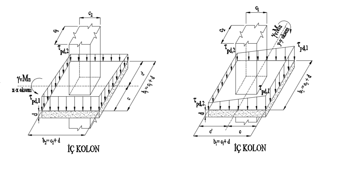
The J values are the sum of the polar inertia and second moments of inertia of the surfaces forming the punching area (Az). TBDY Equation 7.28 calculates this value according to the loading direction considering the γf coefficient.
Calculation of J and γf Coefficients for Strong Axis (Major Direction)
The coefficients γf(maj) and γv(maj) are calculated as follows.
'%3e%3cg transform='translate(167%2c0)'%3e%3cg transform='translate(-13%2c0)'%3e%3cg transform='translate(0%2c278)'%3e%3cuse xlink:href='%23MJMATHI-3B3' x='0' y='0'%3e%3c/use%3e%3cg transform='translate(518%2c-187)'%3e%3cuse transform='scale(0.707)' xlink:href='%23MJMATHI-66' x='0' y='0'%3e%3c/use%3e%3cuse transform='scale(0.707)' xlink:href='%23MJMAIN-28' x='550' y='0'%3e%3c/use%3e%3cuse transform='scale(0.707)' xlink:href='%23MJMATHI-6D' x='940' y='0'%3e%3c/use%3e%3cuse transform='scale(0.707)' xlink:href='%23MJMATHI-61' x='1818' y='0'%3e%3c/use%3e%3cuse transform='scale(0.707)' xlink:href='%23MJMATHI-6A' x='2348' y='0'%3e%3c/use%3e%3cuse transform='scale(0.707)' xlink:href='%23MJMAIN-29' x='2760' y='0'%3e%3c/use%3e%3c/g%3e%3cuse xlink:href='%23MJMAIN-3D' x='3123' y='0'%3e%3c/use%3e%3cg transform='translate(3902%2c0)'%3e%3cg transform='translate(397%2c0)'%3e%3crect stroke='none' width='3945' height='60' x='0' y='220'%3e%3c/rect%3e%3cuse transform='scale(0.707)' xlink:href='%23MJMAIN-31' x='2539' y='602'%3e%3c/use%3e%3cg transform='translate(60%2c-612)'%3e%3cuse transform='scale(0.707)' xlink:href='%23MJMAIN-31' x='0' y='0'%3e%3c/use%3e%3cuse transform='scale(0.707)' xlink:href='%23MJMAIN-2B' x='500' y='0'%3e%3c/use%3e%3cg transform='translate(904%2c0)'%3e%3cg transform='translate(120%2c0)'%3e%3crect stroke='none' width='370' height='60' x='0' y='146'%3e%3c/rect%3e%3cuse transform='scale(0.5)' xlink:href='%23MJMAIN-32' x='119' y='705'%3e%3c/use%3e%3cuse transform='scale(0.5)' xlink:href='%23MJMAIN-33' x='119' y='-664'%3e%3c/use%3e%3c/g%3e%3c/g%3e%3cg transform='translate(1514%2c0)'%3e%3cuse transform='scale(0.707)' xlink:href='%23MJSZ1-221A' x='0' y='-6'%3e%3c/use%3e%3crect stroke='none' width='1603' height='42' x='707' y='555'%3e%3c/rect%3e%3cg transform='translate(707%2c0)'%3e%3cuse transform='scale(0.707)' xlink:href='%23MJMATHI-62' x='0' y='0'%3e%3c/use%3e%3cuse transform='scale(0.5)' xlink:href='%23MJMAIN-31' x='607' y='-213'%3e%3c/use%3e%3cuse transform='scale(0.707)' xlink:href='%23MJMAIN-2F' x='883' y='0'%3e%3c/use%3e%3cg transform='translate(978%2c0)'%3e%3cuse transform='scale(0.707)' xlink:href='%23MJMATHI-62' x='0' y='0'%3e%3c/use%3e%3cuse transform='scale(0.5)' xlink:href='%23MJMAIN-32' x='607' y='-213'%3e%3c/use%3e%3c/g%3e%3c/g%3e%3c/g%3e%3c/g%3e%3c/g%3e%3c/g%3e%3cuse xlink:href='%23MJMAIN-3D' x='8643' y='0'%3e%3c/use%3e%3cg transform='translate(9421%2c0)'%3e%3cg transform='translate(397%2c0)'%3e%3crect stroke='none' width='5213' height='60' x='0' y='220'%3e%3c/rect%3e%3cuse transform='scale(0.707)' xlink:href='%23MJMAIN-31' x='3436' y='602'%3e%3c/use%3e%3cg transform='translate(60%2c-612)'%3e%3cuse transform='scale(0.707)' xlink:href='%23MJMAIN-31' x='0' y='0'%3e%3c/use%3e%3cuse transform='scale(0.707)' xlink:href='%23MJMAIN-2B' x='500' y='0'%3e%3c/use%3e%3cg transform='translate(904%2c0)'%3e%3cg transform='translate(120%2c0)'%3e%3crect stroke='none' width='370' height='60' x='0' y='146'%3e%3c/rect%3e%3cuse transform='scale(0.5)' xlink:href='%23MJMAIN-32' x='119' y='705'%3e%3c/use%3e%3cuse transform='scale(0.5)' xlink:href='%23MJMAIN-33' x='119' y='-664'%3e%3c/use%3e%3c/g%3e%3c/g%3e%3cg transform='translate(1514%2c0)'%3e%3cuse transform='scale(0.707)' xlink:href='%23MJSZ1-221A' x='0' y='-6'%3e%3c/use%3e%3crect stroke='none' width='2871' height='42' x='707' y='555'%3e%3c/rect%3e%3cg transform='translate(707%2c0)'%3e%3cuse transform='scale(0.707)' xlink:href='%23MJMAIN-31'%3e%3c/use%3e%3cuse transform='scale(0.707)' xlink:href='%23MJMAIN-2E' x='500' y='0'%3e%3c/use%3e%3cuse transform='scale(0.707)' xlink:href='%23MJMAIN-32' x='779' y='0'%3e%3c/use%3e%3cuse transform='scale(0.707)' xlink:href='%23MJMAIN-34' x='1279' y='0'%3e%3c/use%3e%3cuse transform='scale(0.707)' xlink:href='%23MJMAIN-2F' x='1779' y='0'%3e%3c/use%3e%3cg transform='translate(1612%2c0)'%3e%3cuse transform='scale(0.707)' xlink:href='%23MJMAIN-31'%3e%3c/use%3e%3cuse transform='scale(0.707)' xlink:href='%23MJMAIN-2E' x='500' y='0'%3e%3c/use%3e%3cuse transform='scale(0.707)' xlink:href='%23MJMAIN-30' x='779' y='0'%3e%3c/use%3e%3cuse transform='scale(0.707)' xlink:href='%23MJMAIN-34' x='1279' y='0'%3e%3c/use%3e%3c/g%3e%3c/g%3e%3c/g%3e%3c/g%3e%3c/g%3e%3c/g%3e%3cuse xlink:href='%23MJMAIN-3D' x='15430' y='0'%3e%3c/use%3e%3cg transform='translate(16486%2c0)'%3e%3cuse xlink:href='%23MJMAIN-30'%3e%3c/use%3e%3cuse xlink:href='%23MJMAIN-2E' x='500' y='0'%3e%3c/use%3e%3cuse xlink:href='%23MJMAIN-35' x='779' y='0'%3e%3c/use%3e%3cuse xlink:href='%23MJMAIN-37' x='1279' y='0'%3e%3c/use%3e%3cuse xlink:href='%23MJMAIN-39' x='1780' y='0'%3e%3c/use%3e%3c/g%3e%3c/g%3e%3c/g%3e%3c/g%3e%3c/g%3e%3c/svg%3e)
'%3e%3cg transform='translate(167%2c0)'%3e%3cg transform='translate(-13%2c0)'%3e%3cg transform='translate(0%2c32)'%3e%3cuse xlink:href='%23MJMATHI-3B3' x='0' y='0'%3e%3c/use%3e%3cg transform='translate(518%2c-187)'%3e%3cuse transform='scale(0.707)' xlink:href='%23MJMATHI-76' x='0' y='0'%3e%3c/use%3e%3cuse transform='scale(0.707)' xlink:href='%23MJMAIN-28' x='485' y='0'%3e%3c/use%3e%3cuse transform='scale(0.707)' xlink:href='%23MJMATHI-6D' x='875' y='0'%3e%3c/use%3e%3cuse transform='scale(0.707)' xlink:href='%23MJMATHI-61' x='1753' y='0'%3e%3c/use%3e%3cuse transform='scale(0.707)' xlink:href='%23MJMATHI-6A' x='2283' y='0'%3e%3c/use%3e%3cuse transform='scale(0.707)' xlink:href='%23MJMAIN-29' x='2695' y='0'%3e%3c/use%3e%3c/g%3e%3cuse xlink:href='%23MJMAIN-3D' x='3077' y='0'%3e%3c/use%3e%3cuse xlink:href='%23MJMAIN-31' x='4133' y='0'%3e%3c/use%3e%3cuse xlink:href='%23MJMAIN-2212' x='4856' y='0'%3e%3c/use%3e%3cg transform='translate(5857%2c0)'%3e%3cuse xlink:href='%23MJMATHI-3B3' x='0' y='0'%3e%3c/use%3e%3cg transform='translate(518%2c-187)'%3e%3cuse transform='scale(0.707)' xlink:href='%23MJMATHI-66' x='0' y='0'%3e%3c/use%3e%3cuse transform='scale(0.707)' xlink:href='%23MJMAIN-28' x='550' y='0'%3e%3c/use%3e%3cuse transform='scale(0.707)' xlink:href='%23MJMATHI-6D' x='940' y='0'%3e%3c/use%3e%3cuse transform='scale(0.707)' xlink:href='%23MJMATHI-61' x='1818' y='0'%3e%3c/use%3e%3cuse transform='scale(0.707)' xlink:href='%23MJMATHI-6A' x='2348' y='0'%3e%3c/use%3e%3cuse transform='scale(0.707)' xlink:href='%23MJMAIN-29' x='2760' y='0'%3e%3c/use%3e%3c/g%3e%3c/g%3e%3cuse xlink:href='%23MJMAIN-3D' x='8981' y='0'%3e%3c/use%3e%3cuse xlink:href='%23MJMAIN-31' x='10037' y='0'%3e%3c/use%3e%3cuse xlink:href='%23MJMAIN-2212' x='10760' y='0'%3e%3c/use%3e%3cg transform='translate(11760%2c0)'%3e%3cuse xlink:href='%23MJMAIN-30'%3e%3c/use%3e%3cuse xlink:href='%23MJMAIN-2E' x='500' y='0'%3e%3c/use%3e%3cuse xlink:href='%23MJMAIN-35' x='779' y='0'%3e%3c/use%3e%3cuse xlink:href='%23MJMAIN-37' x='1279' y='0'%3e%3c/use%3e%3cuse xlink:href='%23MJMAIN-39' x='1780' y='0'%3e%3c/use%3e%3c/g%3e%3cuse xlink:href='%23MJMAIN-3D' x='14319' y='0'%3e%3c/use%3e%3cg transform='translate(15375%2c0)'%3e%3cuse xlink:href='%23MJMAIN-30'%3e%3c/use%3e%3cuse xlink:href='%23MJMAIN-2E' x='500' y='0'%3e%3c/use%3e%3cuse xlink:href='%23MJMAIN-34' x='779' y='0'%3e%3c/use%3e%3cuse xlink:href='%23MJMAIN-32' x='1279' y='0'%3e%3c/use%3e%3cuse xlink:href='%23MJMAIN-31' x='1780' y='0'%3e%3c/use%3e%3c/g%3e%3c/g%3e%3c/g%3e%3c/g%3e%3c/g%3e%3c/svg%3e)
The following operations are performed to find the J (maj) value.
c (maj) is the center of gravity distance perpendicular to the moment vector, which is considered when finding the J value ( J (maj) ) on the strong axis of the section. Since the punching circumference is rectangular,
'%3e%3cg transform='translate(167%2c0)'%3e%3cg transform='translate(-13%2c0)'%3e%3cg transform='translate(0%2c32)'%3e%3cuse xlink:href='%23MJMATHI-63' x='0' y='0'%3e%3c/use%3e%3cg transform='translate(433%2c-187)'%3e%3cuse transform='scale(0.707)' xlink:href='%23MJMAIN-28' x='0' y='0'%3e%3c/use%3e%3cuse transform='scale(0.707)' xlink:href='%23MJMATHI-6D' x='389' y='0'%3e%3c/use%3e%3cuse transform='scale(0.707)' xlink:href='%23MJMATHI-61' x='1268' y='0'%3e%3c/use%3e%3cuse transform='scale(0.707)' xlink:href='%23MJMATHI-6A' x='1797' y='0'%3e%3c/use%3e%3cuse transform='scale(0.707)' xlink:href='%23MJMAIN-29' x='2210' y='0'%3e%3c/use%3e%3c/g%3e%3cuse xlink:href='%23MJMAIN-3D' x='2649' y='0'%3e%3c/use%3e%3cg transform='translate(3705%2c0)'%3e%3cuse xlink:href='%23MJMATHI-62' x='0' y='0'%3e%3c/use%3e%3cuse transform='scale(0.707)' xlink:href='%23MJMAIN-31' x='607' y='-213'%3e%3c/use%3e%3c/g%3e%3cuse xlink:href='%23MJMAIN-2F' x='4589' y='0'%3e%3c/use%3e%3cuse xlink:href='%23MJMAIN-32' x='5089' y='0'%3e%3c/use%3e%3cuse xlink:href='%23MJMAIN-3D' x='5867' y='0'%3e%3c/use%3e%3cg transform='translate(6924%2c0)'%3e%3cuse xlink:href='%23MJMAIN-31'%3e%3c/use%3e%3cuse xlink:href='%23MJMAIN-32' x='500' y='0'%3e%3c/use%3e%3cuse xlink:href='%23MJMAIN-34' x='1001' y='0'%3e%3c/use%3e%3c/g%3e%3cuse xlink:href='%23MJMAIN-2F' x='8425' y='0'%3e%3c/use%3e%3cuse xlink:href='%23MJMAIN-32' x='8926' y='0'%3e%3c/use%3e%3cuse xlink:href='%23MJMAIN-3D' x='9704' y='0'%3e%3c/use%3e%3cg transform='translate(10760%2c0)'%3e%3cuse xlink:href='%23MJMAIN-36'%3e%3c/use%3e%3cuse xlink:href='%23MJMAIN-32' x='500' y='0'%3e%3c/use%3e%3c/g%3e%3cuse xlink:href='%23MJMATHI-63' x='12039' y='0'%3e%3c/use%3e%3cuse xlink:href='%23MJMATHI-6D' x='12472' y='0'%3e%3c/use%3e%3cuse xlink:href='%23MJMAIN-3D' x='13629' y='0'%3e%3c/use%3e%3cg transform='translate(14685%2c0)'%3e%3cuse xlink:href='%23MJMAIN-30'%3e%3c/use%3e%3cuse xlink:href='%23MJMAIN-2E' x='500' y='0'%3e%3c/use%3e%3cuse xlink:href='%23MJMAIN-36' x='779' y='0'%3e%3c/use%3e%3cuse xlink:href='%23MJMAIN-32' x='1279' y='0'%3e%3c/use%3e%3c/g%3e%3cuse xlink:href='%23MJMATHI-6D' x='16743' y='0'%3e%3c/use%3e%3c/g%3e%3c/g%3e%3c/g%3e%3c/g%3e%3c/svg%3e)
'%3e%3cg transform='translate(167%2c0)'%3e%3cg transform='translate(-13%2c0)'%3e%3cg transform='translate(0%2c122)'%3e%3cuse xlink:href='%23MJMATHI-63' x='0' y='0'%3e%3c/use%3e%3cuse transform='scale(0.707)' xlink:href='%23MJMAIN-2032' x='613' y='445'%3e%3c/use%3e%3cg transform='translate(433%2c-367)'%3e%3cuse transform='scale(0.707)' xlink:href='%23MJMAIN-28' x='0' y='0'%3e%3c/use%3e%3cuse transform='scale(0.707)' xlink:href='%23MJMATHI-6D' x='389' y='0'%3e%3c/use%3e%3cuse transform='scale(0.707)' xlink:href='%23MJMATHI-61' x='1268' y='0'%3e%3c/use%3e%3cuse transform='scale(0.707)' xlink:href='%23MJMATHI-6A' x='1797' y='0'%3e%3c/use%3e%3cuse transform='scale(0.707)' xlink:href='%23MJMAIN-29' x='2210' y='0'%3e%3c/use%3e%3c/g%3e%3cuse xlink:href='%23MJMAIN-3D' x='2649' y='0'%3e%3c/use%3e%3cg transform='translate(3705%2c0)'%3e%3cuse xlink:href='%23MJMATHI-62' x='0' y='0'%3e%3c/use%3e%3cuse transform='scale(0.707)' xlink:href='%23MJMAIN-31' x='607' y='-213'%3e%3c/use%3e%3c/g%3e%3cuse xlink:href='%23MJMAIN-2212' x='4811' y='0'%3e%3c/use%3e%3cg transform='translate(5812%2c0)'%3e%3cuse xlink:href='%23MJMATHI-63' x='0' y='0'%3e%3c/use%3e%3cg transform='translate(433%2c-187)'%3e%3cuse transform='scale(0.707)' xlink:href='%23MJMAIN-28' x='0' y='0'%3e%3c/use%3e%3cuse transform='scale(0.707)' xlink:href='%23MJMATHI-6D' x='389' y='0'%3e%3c/use%3e%3cuse transform='scale(0.707)' xlink:href='%23MJMATHI-61' x='1268' y='0'%3e%3c/use%3e%3cuse transform='scale(0.707)' xlink:href='%23MJMATHI-6A' x='1797' y='0'%3e%3c/use%3e%3cuse transform='scale(0.707)' xlink:href='%23MJMAIN-29' x='2210' y='0'%3e%3c/use%3e%3c/g%3e%3c/g%3e%3cuse xlink:href='%23MJMAIN-3D' x='8461' y='0'%3e%3c/use%3e%3cg transform='translate(9517%2c0)'%3e%3cuse xlink:href='%23MJMAIN-31'%3e%3c/use%3e%3cuse xlink:href='%23MJMAIN-32' x='500' y='0'%3e%3c/use%3e%3cuse xlink:href='%23MJMAIN-34' x='1001' y='0'%3e%3c/use%3e%3c/g%3e%3cuse xlink:href='%23MJMAIN-2212' x='11241' y='0'%3e%3c/use%3e%3cg transform='translate(12242%2c0)'%3e%3cuse xlink:href='%23MJMAIN-36'%3e%3c/use%3e%3cuse xlink:href='%23MJMAIN-32' x='500' y='0'%3e%3c/use%3e%3c/g%3e%3cuse xlink:href='%23MJMAIN-3D' x='13520' y='0'%3e%3c/use%3e%3cg transform='translate(14577%2c0)'%3e%3cuse xlink:href='%23MJMAIN-36'%3e%3c/use%3e%3cuse xlink:href='%23MJMAIN-32' x='500' y='0'%3e%3c/use%3e%3c/g%3e%3cuse xlink:href='%23MJMATHI-63' x='15855' y='0'%3e%3c/use%3e%3cuse xlink:href='%23MJMATHI-6D' x='16289' y='0'%3e%3c/use%3e%3cuse xlink:href='%23MJMAIN-3D' x='17445' y='0'%3e%3c/use%3e%3cg transform='translate(18502%2c0)'%3e%3cuse xlink:href='%23MJMAIN-30'%3e%3c/use%3e%3cuse xlink:href='%23MJMAIN-2E' x='500' y='0'%3e%3c/use%3e%3cuse xlink:href='%23MJMAIN-36' x='779' y='0'%3e%3c/use%3e%3cuse xlink:href='%23MJMAIN-32' x='1279' y='0'%3e%3c/use%3e%3c/g%3e%3cuse xlink:href='%23MJMATHI-6D' x='20559' y='0'%3e%3c/use%3e%3c/g%3e%3c/g%3e%3c/g%3e%3c/g%3e%3c/svg%3e)
The polar inertia and second moments of inertia are calculated as follows, respectively.
'%3e%3cg transform='translate(167%2c0)'%3e%3cg transform='translate(-13%2c0)'%3e%3cg transform='translate(0%2c-41)'%3e%3cuse xlink:href='%23MJMATHI-4A' x='0' y='0'%3e%3c/use%3e%3cg transform='translate(555%2c-187)'%3e%3cuse transform='scale(0.707)' xlink:href='%23MJMAIN-31' x='0' y='0'%3e%3c/use%3e%3cuse transform='scale(0.707)' xlink:href='%23MJMAIN-28' x='500' y='0'%3e%3c/use%3e%3cuse transform='scale(0.707)' xlink:href='%23MJMATHI-6D' x='890' y='0'%3e%3c/use%3e%3cuse transform='scale(0.707)' xlink:href='%23MJMATHI-61' x='1768' y='0'%3e%3c/use%3e%3cuse transform='scale(0.707)' xlink:href='%23MJMATHI-6A' x='2298' y='0'%3e%3c/use%3e%3cuse transform='scale(0.707)' xlink:href='%23MJMAIN-29' x='2710' y='0'%3e%3c/use%3e%3c/g%3e%3cuse xlink:href='%23MJMAIN-3D' x='3125' y='0'%3e%3c/use%3e%3cg transform='translate(4181%2c0)'%3e%3cuse xlink:href='%23MJSZ2-28'%3e%3c/use%3e%3cg transform='translate(597%2c0)'%3e%3cg transform='translate(120%2c0)'%3e%3crect stroke='none' width='1436' height='60' x='0' y='220'%3e%3c/rect%3e%3cg transform='translate(60%2c531)'%3e%3cuse transform='scale(0.707)' xlink:href='%23MJMATHI-62' x='0' y='0'%3e%3c/use%3e%3cuse transform='scale(0.5)' xlink:href='%23MJMAIN-31' x='607' y='-213'%3e%3c/use%3e%3cg transform='translate(624%2c0)'%3e%3cuse transform='scale(0.707)' xlink:href='%23MJMATHI-64' x='0' y='0'%3e%3c/use%3e%3cuse transform='scale(0.5)' xlink:href='%23MJMAIN-33' x='741' y='596'%3e%3c/use%3e%3c/g%3e%3c/g%3e%3cg transform='translate(364%2c-397)'%3e%3cuse transform='scale(0.707)' xlink:href='%23MJMAIN-31'%3e%3c/use%3e%3cuse transform='scale(0.707)' xlink:href='%23MJMAIN-32' x='500' y='0'%3e%3c/use%3e%3c/g%3e%3c/g%3e%3c/g%3e%3cuse xlink:href='%23MJMAIN-2B' x='2496' y='0'%3e%3c/use%3e%3cg transform='translate(3274%2c0)'%3e%3cg transform='translate(342%2c0)'%3e%3crect stroke='none' width='1114' height='60' x='0' y='220'%3e%3c/rect%3e%3cg transform='translate(60%2c600)'%3e%3cuse transform='scale(0.707)' xlink:href='%23MJMATHI-62' x='0' y='0'%3e%3c/use%3e%3cuse transform='scale(0.5)' xlink:href='%23MJMAIN-33' x='607' y='596'%3e%3c/use%3e%3cuse transform='scale(0.5)' xlink:href='%23MJMAIN-31' x='607' y='-350'%3e%3c/use%3e%3cuse transform='scale(0.707)' xlink:href='%23MJMATHI-64' x='883' y='0'%3e%3c/use%3e%3c/g%3e%3cg transform='translate(203%2c-397)'%3e%3cuse transform='scale(0.707)' xlink:href='%23MJMAIN-31'%3e%3c/use%3e%3cuse transform='scale(0.707)' xlink:href='%23MJMAIN-32' x='500' y='0'%3e%3c/use%3e%3c/g%3e%3c/g%3e%3c/g%3e%3cuse xlink:href='%23MJSZ2-29' x='4851' y='-1'%3e%3c/use%3e%3c/g%3e%3cuse xlink:href='%23MJMAIN-D7' x='9853' y='0'%3e%3c/use%3e%3cuse xlink:href='%23MJMAIN-32' x='10853' y='0'%3e%3c/use%3e%3cuse xlink:href='%23MJMAIN-3D' x='11632' y='0'%3e%3c/use%3e%3cg transform='translate(12688%2c0)'%3e%3cuse xlink:href='%23MJSZ2-28'%3e%3c/use%3e%3cg transform='translate(597%2c0)'%3e%3cg transform='translate(120%2c0)'%3e%3crect stroke='none' width='3508' height='60' x='0' y='220'%3e%3c/rect%3e%3cg transform='translate(60%2c441)'%3e%3cuse transform='scale(0.707)' xlink:href='%23MJMAIN-31'%3e%3c/use%3e%3cuse transform='scale(0.707)' xlink:href='%23MJMAIN-2E' x='500' y='0'%3e%3c/use%3e%3cuse transform='scale(0.707)' xlink:href='%23MJMAIN-32' x='779' y='0'%3e%3c/use%3e%3cuse transform='scale(0.707)' xlink:href='%23MJMAIN-34' x='1279' y='0'%3e%3c/use%3e%3cuse transform='scale(0.707)' xlink:href='%23MJMAIN-D7' x='1779' y='0'%3e%3c/use%3e%3cg transform='translate(1809%2c0)'%3e%3cuse transform='scale(0.707)' xlink:href='%23MJMAIN-30'%3e%3c/use%3e%3cuse transform='scale(0.707)' xlink:href='%23MJMAIN-2E' x='500' y='0'%3e%3c/use%3e%3cuse transform='scale(0.707)' xlink:href='%23MJMAIN-32' x='779' y='0'%3e%3c/use%3e%3cuse transform='scale(0.707)' xlink:href='%23MJMAIN-34' x='1279' y='0'%3e%3c/use%3e%3cuse transform='scale(0.5)' xlink:href='%23MJMAIN-33' x='2517' y='572'%3e%3c/use%3e%3c/g%3e%3c/g%3e%3cg transform='translate(1400%2c-397)'%3e%3cuse transform='scale(0.707)' xlink:href='%23MJMAIN-31'%3e%3c/use%3e%3cuse transform='scale(0.707)' xlink:href='%23MJMAIN-32' x='500' y='0'%3e%3c/use%3e%3c/g%3e%3c/g%3e%3c/g%3e%3cuse xlink:href='%23MJMAIN-2B' x='4568' y='0'%3e%3c/use%3e%3cg transform='translate(5346%2c0)'%3e%3cg transform='translate(342%2c0)'%3e%3crect stroke='none' width='3508' height='60' x='0' y='220'%3e%3c/rect%3e%3cg transform='translate(60%2c441)'%3e%3cuse transform='scale(0.707)' xlink:href='%23MJMAIN-31'%3e%3c/use%3e%3cuse transform='scale(0.707)' xlink:href='%23MJMAIN-2E' x='500' y='0'%3e%3c/use%3e%3cuse transform='scale(0.707)' xlink:href='%23MJMAIN-32' x='779' y='0'%3e%3c/use%3e%3cuse transform='scale(0.707)' xlink:href='%23MJMAIN-34' x='1279' y='0'%3e%3c/use%3e%3cuse transform='scale(0.5)' xlink:href='%23MJMAIN-33' x='2517' y='572'%3e%3c/use%3e%3cuse transform='scale(0.707)' xlink:href='%23MJMAIN-D7' x='2233' y='0'%3e%3c/use%3e%3cg transform='translate(2130%2c0)'%3e%3cuse transform='scale(0.707)' xlink:href='%23MJMAIN-30'%3e%3c/use%3e%3cuse transform='scale(0.707)' xlink:href='%23MJMAIN-2E' x='500' y='0'%3e%3c/use%3e%3cuse transform='scale(0.707)' xlink:href='%23MJMAIN-32' x='779' y='0'%3e%3c/use%3e%3cuse transform='scale(0.707)' xlink:href='%23MJMAIN-34' x='1279' y='0'%3e%3c/use%3e%3c/g%3e%3c/g%3e%3cg transform='translate(1400%2c-397)'%3e%3cuse transform='scale(0.707)' xlink:href='%23MJMAIN-31'%3e%3c/use%3e%3cuse transform='scale(0.707)' xlink:href='%23MJMAIN-32' x='500' y='0'%3e%3c/use%3e%3c/g%3e%3c/g%3e%3c/g%3e%3cuse xlink:href='%23MJSZ2-29' x='9317' y='-1'%3e%3c/use%3e%3c/g%3e%3cuse xlink:href='%23MJMAIN-D7' x='22825' y='0'%3e%3c/use%3e%3cuse xlink:href='%23MJMAIN-32' x='23826' y='0'%3e%3c/use%3e%3cuse xlink:href='%23MJMAIN-3D' x='24604' y='0'%3e%3c/use%3e%3cg transform='translate(25661%2c0)'%3e%3cuse xlink:href='%23MJMAIN-30'%3e%3c/use%3e%3cuse xlink:href='%23MJMAIN-2E' x='500' y='0'%3e%3c/use%3e%3cuse xlink:href='%23MJMAIN-30' x='779' y='0'%3e%3c/use%3e%3cuse xlink:href='%23MJMAIN-37' x='1279' y='0'%3e%3c/use%3e%3cuse xlink:href='%23MJMAIN-39' x='1780' y='0'%3e%3c/use%3e%3cuse xlink:href='%23MJMAIN-31' x='2280' y='0'%3e%3c/use%3e%3cuse xlink:href='%23MJMAIN-32' x='2781' y='0'%3e%3c/use%3e%3cuse xlink:href='%23MJMAIN-32' x='3281' y='0'%3e%3c/use%3e%3c/g%3e%3cg transform='translate(29721%2c0)'%3e%3cuse xlink:href='%23MJMATHI-6D' x='0' y='0'%3e%3c/use%3e%3cuse transform='scale(0.707)' xlink:href='%23MJMAIN-34' x='1242' y='513'%3e%3c/use%3e%3c/g%3e%3c/g%3e%3c/g%3e%3c/g%3e%3c/g%3e%3c/svg%3e)
'%3e%3cg transform='translate(167%2c0)'%3e%3cg transform='translate(-13%2c0)'%3e%3cg transform='translate(0%2c89)'%3e%3cuse xlink:href='%23MJMATHI-4A' x='0' y='0'%3e%3c/use%3e%3cg transform='translate(555%2c-187)'%3e%3cuse transform='scale(0.707)' xlink:href='%23MJMAIN-32' x='0' y='0'%3e%3c/use%3e%3cuse transform='scale(0.707)' xlink:href='%23MJMAIN-28' x='500' y='0'%3e%3c/use%3e%3cuse transform='scale(0.707)' xlink:href='%23MJMATHI-6D' x='890' y='0'%3e%3c/use%3e%3cuse transform='scale(0.707)' xlink:href='%23MJMATHI-61' x='1768' y='0'%3e%3c/use%3e%3cuse transform='scale(0.707)' xlink:href='%23MJMATHI-6A' x='2298' y='0'%3e%3c/use%3e%3cuse transform='scale(0.707)' xlink:href='%23MJMAIN-29' x='2710' y='0'%3e%3c/use%3e%3c/g%3e%3cuse xlink:href='%23MJMAIN-3D' x='3125' y='0'%3e%3c/use%3e%3cg transform='translate(4181%2c0)'%3e%3cuse xlink:href='%23MJMATHI-62' x='0' y='0'%3e%3c/use%3e%3cuse transform='scale(0.707)' xlink:href='%23MJMAIN-32' x='607' y='-213'%3e%3c/use%3e%3c/g%3e%3cuse xlink:href='%23MJMATHI-64' x='5064' y='0'%3e%3c/use%3e%3cuse xlink:href='%23MJMAIN-D7' x='5810' y='0'%3e%3c/use%3e%3cg transform='translate(6811%2c0)'%3e%3cuse xlink:href='%23MJMATHI-63' x='0' y='0'%3e%3c/use%3e%3cuse transform='scale(0.707)' xlink:href='%23MJMAIN-32' x='613' y='488'%3e%3c/use%3e%3cg transform='translate(433%2c-367)'%3e%3cuse transform='scale(0.707)' xlink:href='%23MJMAIN-28' x='0' y='0'%3e%3c/use%3e%3cuse transform='scale(0.707)' xlink:href='%23MJMATHI-6D' x='389' y='0'%3e%3c/use%3e%3cuse transform='scale(0.707)' xlink:href='%23MJMATHI-61' x='1268' y='0'%3e%3c/use%3e%3cuse transform='scale(0.707)' xlink:href='%23MJMATHI-6A' x='1797' y='0'%3e%3c/use%3e%3cuse transform='scale(0.707)' xlink:href='%23MJMAIN-29' x='2210' y='0'%3e%3c/use%3e%3c/g%3e%3c/g%3e%3cuse xlink:href='%23MJMAIN-D7' x='9405' y='0'%3e%3c/use%3e%3cuse xlink:href='%23MJMAIN-32' x='10406' y='0'%3e%3c/use%3e%3cuse xlink:href='%23MJMAIN-3D' x='11184' y='0'%3e%3c/use%3e%3cg transform='translate(12240%2c0)'%3e%3cuse xlink:href='%23MJMAIN-31'%3e%3c/use%3e%3cuse xlink:href='%23MJMAIN-2E' x='500' y='0'%3e%3c/use%3e%3cuse xlink:href='%23MJMAIN-30' x='779' y='0'%3e%3c/use%3e%3cuse xlink:href='%23MJMAIN-34' x='1279' y='0'%3e%3c/use%3e%3c/g%3e%3cuse xlink:href='%23MJMAIN-D7' x='14242' y='0'%3e%3c/use%3e%3cg transform='translate(15243%2c0)'%3e%3cuse xlink:href='%23MJMAIN-30'%3e%3c/use%3e%3cuse xlink:href='%23MJMAIN-2E' x='500' y='0'%3e%3c/use%3e%3cuse xlink:href='%23MJMAIN-32' x='779' y='0'%3e%3c/use%3e%3cuse xlink:href='%23MJMAIN-34' x='1279' y='0'%3e%3c/use%3e%3c/g%3e%3cuse xlink:href='%23MJMAIN-D7' x='17245' y='0'%3e%3c/use%3e%3cg transform='translate(18246%2c0)'%3e%3cuse xlink:href='%23MJMAIN-30'%3e%3c/use%3e%3cuse xlink:href='%23MJMAIN-2E' x='500' y='0'%3e%3c/use%3e%3cuse xlink:href='%23MJMAIN-36' x='779' y='0'%3e%3c/use%3e%3cuse xlink:href='%23MJMAIN-32' x='1279' y='0'%3e%3c/use%3e%3cuse transform='scale(0.707)' xlink:href='%23MJMAIN-32' x='2517' y='557'%3e%3c/use%3e%3c/g%3e%3cuse xlink:href='%23MJMAIN-D7' x='20702' y='0'%3e%3c/use%3e%3cuse xlink:href='%23MJMAIN-32' x='21703' y='0'%3e%3c/use%3e%3cuse xlink:href='%23MJMAIN-3D' x='22481' y='0'%3e%3c/use%3e%3cg transform='translate(23537%2c0)'%3e%3cuse xlink:href='%23MJMAIN-30'%3e%3c/use%3e%3cuse xlink:href='%23MJMAIN-2E' x='500' y='0'%3e%3c/use%3e%3cuse xlink:href='%23MJMAIN-31' x='779' y='0'%3e%3c/use%3e%3cuse xlink:href='%23MJMAIN-39' x='1279' y='0'%3e%3c/use%3e%3cuse xlink:href='%23MJMAIN-31' x='1780' y='0'%3e%3c/use%3e%3cuse xlink:href='%23MJMAIN-38' x='2280' y='0'%3e%3c/use%3e%3cuse xlink:href='%23MJMAIN-39' x='2781' y='0'%3e%3c/use%3e%3cuse xlink:href='%23MJMAIN-32' x='3281' y='0'%3e%3c/use%3e%3cuse xlink:href='%23MJMAIN-34' x='3782' y='0'%3e%3c/use%3e%3cuse xlink:href='%23MJMAIN-38' x='4282' y='0'%3e%3c/use%3e%3c/g%3e%3cg transform='translate(28598%2c0)'%3e%3cuse xlink:href='%23MJMATHI-6D' x='0' y='0'%3e%3c/use%3e%3cuse transform='scale(0.707)' xlink:href='%23MJMAIN-34' x='1242' y='513'%3e%3c/use%3e%3c/g%3e%3c/g%3e%3c/g%3e%3c/g%3e%3c/g%3e%3c/svg%3e)
In this case, the sum of the polar inertia and second moments of inertia about the section's strong (major) axis, J (maj), is found as follows.
'%3e%3cg transform='translate(167%2c0)'%3e%3cg transform='translate(-13%2c0)'%3e%3cg transform='translate(0%2c10)'%3e%3cuse xlink:href='%23MJMATHI-4A' x='0' y='0'%3e%3c/use%3e%3cg transform='translate(555%2c-187)'%3e%3cuse transform='scale(0.707)' xlink:href='%23MJMAIN-28' x='0' y='0'%3e%3c/use%3e%3cuse transform='scale(0.707)' xlink:href='%23MJMATHI-6D' x='389' y='0'%3e%3c/use%3e%3cuse transform='scale(0.707)' xlink:href='%23MJMATHI-61' x='1268' y='0'%3e%3c/use%3e%3cuse transform='scale(0.707)' xlink:href='%23MJMATHI-6A' x='1797' y='0'%3e%3c/use%3e%3cuse transform='scale(0.707)' xlink:href='%23MJMAIN-29' x='2210' y='0'%3e%3c/use%3e%3c/g%3e%3cuse xlink:href='%23MJMAIN-3D' x='2771' y='0'%3e%3c/use%3e%3cg transform='translate(3827%2c0)'%3e%3cuse xlink:href='%23MJMATHI-4A' x='0' y='0'%3e%3c/use%3e%3cg transform='translate(555%2c-187)'%3e%3cuse transform='scale(0.707)' xlink:href='%23MJMAIN-31' x='0' y='0'%3e%3c/use%3e%3cuse transform='scale(0.707)' xlink:href='%23MJMAIN-28' x='500' y='0'%3e%3c/use%3e%3cuse transform='scale(0.707)' xlink:href='%23MJMATHI-6D' x='890' y='0'%3e%3c/use%3e%3cuse transform='scale(0.707)' xlink:href='%23MJMATHI-61' x='1768' y='0'%3e%3c/use%3e%3cuse transform='scale(0.707)' xlink:href='%23MJMATHI-6A' x='2298' y='0'%3e%3c/use%3e%3cuse transform='scale(0.707)' xlink:href='%23MJMAIN-29' x='2710' y='0'%3e%3c/use%3e%3c/g%3e%3c/g%3e%3cuse xlink:href='%23MJMAIN-2B' x='6897' y='0'%3e%3c/use%3e%3cg transform='translate(7898%2c0)'%3e%3cuse xlink:href='%23MJMATHI-4A' x='0' y='0'%3e%3c/use%3e%3cg transform='translate(555%2c-187)'%3e%3cuse transform='scale(0.707)' xlink:href='%23MJMAIN-32' x='0' y='0'%3e%3c/use%3e%3cuse transform='scale(0.707)' xlink:href='%23MJMAIN-28' x='500' y='0'%3e%3c/use%3e%3cuse transform='scale(0.707)' xlink:href='%23MJMATHI-6D' x='890' y='0'%3e%3c/use%3e%3cuse transform='scale(0.707)' xlink:href='%23MJMATHI-61' x='1768' y='0'%3e%3c/use%3e%3cuse transform='scale(0.707)' xlink:href='%23MJMATHI-6A' x='2298' y='0'%3e%3c/use%3e%3cuse transform='scale(0.707)' xlink:href='%23MJMAIN-29' x='2710' y='0'%3e%3c/use%3e%3c/g%3e%3c/g%3e%3cuse xlink:href='%23MJMAIN-3D' x='11023' y='0'%3e%3c/use%3e%3cg transform='translate(12079%2c0)'%3e%3cuse xlink:href='%23MJMAIN-30'%3e%3c/use%3e%3cuse xlink:href='%23MJMAIN-2E' x='500' y='0'%3e%3c/use%3e%3cuse xlink:href='%23MJMAIN-30' x='779' y='0'%3e%3c/use%3e%3cuse xlink:href='%23MJMAIN-37' x='1279' y='0'%3e%3c/use%3e%3cuse xlink:href='%23MJMAIN-39' x='1780' y='0'%3e%3c/use%3e%3cuse xlink:href='%23MJMAIN-31' x='2280' y='0'%3e%3c/use%3e%3cuse xlink:href='%23MJMAIN-32' x='2781' y='0'%3e%3c/use%3e%3cuse xlink:href='%23MJMAIN-32' x='3281' y='0'%3e%3c/use%3e%3c/g%3e%3cuse xlink:href='%23MJMAIN-2B' x='16083' y='0'%3e%3c/use%3e%3cg transform='translate(17084%2c0)'%3e%3cuse xlink:href='%23MJMAIN-30'%3e%3c/use%3e%3cuse xlink:href='%23MJMAIN-2E' x='500' y='0'%3e%3c/use%3e%3cuse xlink:href='%23MJMAIN-31' x='779' y='0'%3e%3c/use%3e%3cuse xlink:href='%23MJMAIN-39' x='1279' y='0'%3e%3c/use%3e%3cuse xlink:href='%23MJMAIN-31' x='1780' y='0'%3e%3c/use%3e%3cuse xlink:href='%23MJMAIN-38' x='2280' y='0'%3e%3c/use%3e%3cuse xlink:href='%23MJMAIN-39' x='2781' y='0'%3e%3c/use%3e%3cuse xlink:href='%23MJMAIN-32' x='3281' y='0'%3e%3c/use%3e%3cuse xlink:href='%23MJMAIN-34' x='3782' y='0'%3e%3c/use%3e%3cuse xlink:href='%23MJMAIN-38' x='4282' y='0'%3e%3c/use%3e%3c/g%3e%3cuse xlink:href='%23MJMAIN-3D' x='22145' y='0'%3e%3c/use%3e%3cg transform='translate(23201%2c0)'%3e%3cuse xlink:href='%23MJMAIN-30'%3e%3c/use%3e%3cuse xlink:href='%23MJMAIN-2E' x='500' y='0'%3e%3c/use%3e%3cuse xlink:href='%23MJMAIN-32' x='779' y='0'%3e%3c/use%3e%3cuse xlink:href='%23MJMAIN-37' x='1279' y='0'%3e%3c/use%3e%3cuse xlink:href='%23MJMAIN-31' x='1780' y='0'%3e%3c/use%3e%3cuse xlink:href='%23MJMAIN-30' x='2280' y='0'%3e%3c/use%3e%3cuse xlink:href='%23MJMAIN-31' x='2781' y='0'%3e%3c/use%3e%3cuse xlink:href='%23MJMAIN-34' x='3281' y='0'%3e%3c/use%3e%3cuse xlink:href='%23MJMAIN-34' x='3782' y='0'%3e%3c/use%3e%3cuse xlink:href='%23MJMAIN-38' x='4282' y='0'%3e%3c/use%3e%3c/g%3e%3cg transform='translate(28262%2c0)'%3e%3cuse xlink:href='%23MJMATHI-6D' x='0' y='0'%3e%3c/use%3e%3cuse transform='scale(0.707)' xlink:href='%23MJMAIN-34' x='1242' y='513'%3e%3c/use%3e%3c/g%3e%3cuse xlink:href='%23MJMAIN-3D' x='29872' y='0'%3e%3c/use%3e%3cg transform='translate(30928%2c0)'%3e%3cuse xlink:href='%23MJMAIN-32'%3e%3c/use%3e%3cuse xlink:href='%23MJMAIN-37' x='500' y='0'%3e%3c/use%3e%3cuse xlink:href='%23MJMAIN-31' x='1001' y='0'%3e%3c/use%3e%3cuse xlink:href='%23MJMAIN-30' x='1501' y='0'%3e%3c/use%3e%3cuse xlink:href='%23MJMAIN-31' x='2002' y='0'%3e%3c/use%3e%3cuse xlink:href='%23MJMAIN-34' x='2502' y='0'%3e%3c/use%3e%3cuse xlink:href='%23MJMAIN-34' x='3003' y='0'%3e%3c/use%3e%3cuse xlink:href='%23MJMAIN-38' x='3503' y='0'%3e%3c/use%3e%3c/g%3e%3cuse xlink:href='%23MJMATHI-63' x='35210' y='0'%3e%3c/use%3e%3cg transform='translate(35644%2c0)'%3e%3cuse xlink:href='%23MJMATHI-6D' x='0' y='0'%3e%3c/use%3e%3cuse transform='scale(0.707)' xlink:href='%23MJMAIN-34' x='1242' y='513'%3e%3c/use%3e%3c/g%3e%3c/g%3e%3c/g%3e%3c/g%3e%3c/g%3e%3c/svg%3e)
Calculation of J and γf Coefficients for Weak Axis ( Minor Direction )
The following steps are followed to calculate the γ f(min) and γ v(min) coefficients.
'%3e%3cg transform='translate(167%2c0)'%3e%3cg transform='translate(-13%2c0)'%3e%3cg transform='translate(0%2c278)'%3e%3cuse xlink:href='%23MJMATHI-3B3' x='0' y='0'%3e%3c/use%3e%3cg transform='translate(518%2c-187)'%3e%3cuse transform='scale(0.707)' xlink:href='%23MJMATHI-66' x='0' y='0'%3e%3c/use%3e%3cuse transform='scale(0.707)' xlink:href='%23MJMAIN-28' x='550' y='0'%3e%3c/use%3e%3cuse transform='scale(0.707)' xlink:href='%23MJMATHI-6D' x='940' y='0'%3e%3c/use%3e%3cuse transform='scale(0.707)' xlink:href='%23MJMATHI-69' x='1818' y='0'%3e%3c/use%3e%3cuse transform='scale(0.707)' xlink:href='%23MJMATHI-6E' x='2164' y='0'%3e%3c/use%3e%3cuse transform='scale(0.707)' xlink:href='%23MJMAIN-29' x='2764' y='0'%3e%3c/use%3e%3c/g%3e%3cuse xlink:href='%23MJMAIN-3D' x='3126' y='0'%3e%3c/use%3e%3cg transform='translate(3904%2c0)'%3e%3cg transform='translate(397%2c0)'%3e%3crect stroke='none' width='3945' height='60' x='0' y='220'%3e%3c/rect%3e%3cuse transform='scale(0.707)' xlink:href='%23MJMAIN-31' x='2539' y='602'%3e%3c/use%3e%3cg transform='translate(60%2c-612)'%3e%3cuse transform='scale(0.707)' xlink:href='%23MJMAIN-31' x='0' y='0'%3e%3c/use%3e%3cuse transform='scale(0.707)' xlink:href='%23MJMAIN-2B' x='500' y='0'%3e%3c/use%3e%3cg transform='translate(904%2c0)'%3e%3cg transform='translate(120%2c0)'%3e%3crect stroke='none' width='370' height='60' x='0' y='146'%3e%3c/rect%3e%3cuse transform='scale(0.5)' xlink:href='%23MJMAIN-32' x='119' y='705'%3e%3c/use%3e%3cuse transform='scale(0.5)' xlink:href='%23MJMAIN-33' x='119' y='-664'%3e%3c/use%3e%3c/g%3e%3c/g%3e%3cg transform='translate(1514%2c0)'%3e%3cuse transform='scale(0.707)' xlink:href='%23MJSZ1-221A' x='0' y='-6'%3e%3c/use%3e%3crect stroke='none' width='1603' height='42' x='707' y='555'%3e%3c/rect%3e%3cg transform='translate(707%2c0)'%3e%3cuse transform='scale(0.707)' xlink:href='%23MJMATHI-62' x='0' y='0'%3e%3c/use%3e%3cuse transform='scale(0.5)' xlink:href='%23MJMAIN-32' x='607' y='-213'%3e%3c/use%3e%3cuse transform='scale(0.707)' xlink:href='%23MJMAIN-2F' x='883' y='0'%3e%3c/use%3e%3cg transform='translate(978%2c0)'%3e%3cuse transform='scale(0.707)' xlink:href='%23MJMATHI-62' x='0' y='0'%3e%3c/use%3e%3cuse transform='scale(0.5)' xlink:href='%23MJMAIN-31' x='607' y='-213'%3e%3c/use%3e%3c/g%3e%3c/g%3e%3c/g%3e%3c/g%3e%3c/g%3e%3c/g%3e%3cuse xlink:href='%23MJMAIN-3D' x='8645' y='0'%3e%3c/use%3e%3cg transform='translate(9424%2c0)'%3e%3cg transform='translate(397%2c0)'%3e%3crect stroke='none' width='5213' height='60' x='0' y='220'%3e%3c/rect%3e%3cuse transform='scale(0.707)' xlink:href='%23MJMAIN-31' x='3436' y='602'%3e%3c/use%3e%3cg transform='translate(60%2c-612)'%3e%3cuse transform='scale(0.707)' xlink:href='%23MJMAIN-31' x='0' y='0'%3e%3c/use%3e%3cuse transform='scale(0.707)' xlink:href='%23MJMAIN-2B' x='500' y='0'%3e%3c/use%3e%3cg transform='translate(904%2c0)'%3e%3cg transform='translate(120%2c0)'%3e%3crect stroke='none' width='370' height='60' x='0' y='146'%3e%3c/rect%3e%3cuse transform='scale(0.5)' xlink:href='%23MJMAIN-32' x='119' y='705'%3e%3c/use%3e%3cuse transform='scale(0.5)' xlink:href='%23MJMAIN-33' x='119' y='-664'%3e%3c/use%3e%3c/g%3e%3c/g%3e%3cg transform='translate(1514%2c0)'%3e%3cuse transform='scale(0.707)' xlink:href='%23MJSZ1-221A' x='0' y='-6'%3e%3c/use%3e%3crect stroke='none' width='2871' height='42' x='707' y='555'%3e%3c/rect%3e%3cg transform='translate(707%2c0)'%3e%3cuse transform='scale(0.707)' xlink:href='%23MJMAIN-31'%3e%3c/use%3e%3cuse transform='scale(0.707)' xlink:href='%23MJMAIN-2E' x='500' y='0'%3e%3c/use%3e%3cuse transform='scale(0.707)' xlink:href='%23MJMAIN-30' x='779' y='0'%3e%3c/use%3e%3cuse transform='scale(0.707)' xlink:href='%23MJMAIN-34' x='1279' y='0'%3e%3c/use%3e%3cuse transform='scale(0.707)' xlink:href='%23MJMAIN-2F' x='1779' y='0'%3e%3c/use%3e%3cg transform='translate(1612%2c0)'%3e%3cuse transform='scale(0.707)' xlink:href='%23MJMAIN-31'%3e%3c/use%3e%3cuse transform='scale(0.707)' xlink:href='%23MJMAIN-2E' x='500' y='0'%3e%3c/use%3e%3cuse transform='scale(0.707)' xlink:href='%23MJMAIN-32' x='779' y='0'%3e%3c/use%3e%3cuse transform='scale(0.707)' xlink:href='%23MJMAIN-34' x='1279' y='0'%3e%3c/use%3e%3c/g%3e%3c/g%3e%3c/g%3e%3c/g%3e%3c/g%3e%3c/g%3e%3cuse xlink:href='%23MJMAIN-3D' x='15433' y='0'%3e%3c/use%3e%3cg transform='translate(16489%2c0)'%3e%3cuse xlink:href='%23MJMAIN-30'%3e%3c/use%3e%3cuse xlink:href='%23MJMAIN-2E' x='500' y='0'%3e%3c/use%3e%3cuse xlink:href='%23MJMAIN-36' x='779' y='0'%3e%3c/use%3e%3cuse xlink:href='%23MJMAIN-32' x='1279' y='0'%3e%3c/use%3e%3cuse xlink:href='%23MJMAIN-31' x='1780' y='0'%3e%3c/use%3e%3c/g%3e%3c/g%3e%3c/g%3e%3c/g%3e%3c/g%3e%3c/svg%3e)
'%3e%3cg transform='translate(167%2c0)'%3e%3cg transform='translate(-13%2c0)'%3e%3cg transform='translate(0%2c32)'%3e%3cuse xlink:href='%23MJMATHI-3B3' x='0' y='0'%3e%3c/use%3e%3cg transform='translate(518%2c-187)'%3e%3cuse transform='scale(0.707)' xlink:href='%23MJMATHI-76' x='0' y='0'%3e%3c/use%3e%3cuse transform='scale(0.707)' xlink:href='%23MJMAIN-28' x='485' y='0'%3e%3c/use%3e%3cuse transform='scale(0.707)' xlink:href='%23MJMATHI-6D' x='875' y='0'%3e%3c/use%3e%3cuse transform='scale(0.707)' xlink:href='%23MJMATHI-69' x='1753' y='0'%3e%3c/use%3e%3cuse transform='scale(0.707)' xlink:href='%23MJMATHI-6E' x='2099' y='0'%3e%3c/use%3e%3cuse transform='scale(0.707)' xlink:href='%23MJMAIN-29' x='2699' y='0'%3e%3c/use%3e%3c/g%3e%3cuse xlink:href='%23MJMAIN-3D' x='3080' y='0'%3e%3c/use%3e%3cuse xlink:href='%23MJMAIN-31' x='4136' y='0'%3e%3c/use%3e%3cuse xlink:href='%23MJMAIN-2212' x='4859' y='0'%3e%3c/use%3e%3cg transform='translate(5860%2c0)'%3e%3cuse xlink:href='%23MJMATHI-3B3' x='0' y='0'%3e%3c/use%3e%3cg transform='translate(518%2c-187)'%3e%3cuse transform='scale(0.707)' xlink:href='%23MJMATHI-66' x='0' y='0'%3e%3c/use%3e%3cuse transform='scale(0.707)' xlink:href='%23MJMAIN-28' x='550' y='0'%3e%3c/use%3e%3cuse transform='scale(0.707)' xlink:href='%23MJMATHI-6D' x='940' y='0'%3e%3c/use%3e%3cuse transform='scale(0.707)' xlink:href='%23MJMATHI-61' x='1818' y='0'%3e%3c/use%3e%3cuse transform='scale(0.707)' xlink:href='%23MJMATHI-6A' x='2348' y='0'%3e%3c/use%3e%3cuse transform='scale(0.707)' xlink:href='%23MJMAIN-29' x='2760' y='0'%3e%3c/use%3e%3c/g%3e%3c/g%3e%3cuse xlink:href='%23MJMAIN-3D' x='8983' y='0'%3e%3c/use%3e%3cuse xlink:href='%23MJMAIN-31' x='10040' y='0'%3e%3c/use%3e%3cuse xlink:href='%23MJMAIN-2212' x='10762' y='0'%3e%3c/use%3e%3cg transform='translate(11763%2c0)'%3e%3cuse xlink:href='%23MJMAIN-30'%3e%3c/use%3e%3cuse xlink:href='%23MJMAIN-2E' x='500' y='0'%3e%3c/use%3e%3cuse xlink:href='%23MJMAIN-36' x='779' y='0'%3e%3c/use%3e%3cuse xlink:href='%23MJMAIN-32' x='1279' y='0'%3e%3c/use%3e%3cuse xlink:href='%23MJMAIN-31' x='1780' y='0'%3e%3c/use%3e%3c/g%3e%3cuse xlink:href='%23MJMAIN-3D' x='14321' y='0'%3e%3c/use%3e%3cg transform='translate(15378%2c0)'%3e%3cuse xlink:href='%23MJMAIN-30'%3e%3c/use%3e%3cuse xlink:href='%23MJMAIN-2E' x='500' y='0'%3e%3c/use%3e%3cuse xlink:href='%23MJMAIN-33' x='779' y='0'%3e%3c/use%3e%3cuse xlink:href='%23MJMAIN-37' x='1279' y='0'%3e%3c/use%3e%3cuse xlink:href='%23MJMAIN-39' x='1780' y='0'%3e%3c/use%3e%3c/g%3e%3c/g%3e%3c/g%3e%3c/g%3e%3c/g%3e%3c/svg%3e)
The J(min) value is found as follows.
The c(min) value is the center of gravity distance perpendicular to the moment vector, which is considered when finding the J value (J (min)) on the weak axis of the section. Since the punching circumference is rectangular,
'%3e%3cg transform='translate(167%2c0)'%3e%3cg transform='translate(-13%2c0)'%3e%3cg transform='translate(0%2c32)'%3e%3cuse xlink:href='%23MJMATHI-63' x='0' y='0'%3e%3c/use%3e%3cg transform='translate(433%2c-187)'%3e%3cuse transform='scale(0.707)' xlink:href='%23MJMAIN-28' x='0' y='0'%3e%3c/use%3e%3cuse transform='scale(0.707)' xlink:href='%23MJMATHI-6D' x='389' y='0'%3e%3c/use%3e%3cuse transform='scale(0.707)' xlink:href='%23MJMATHI-69' x='1268' y='0'%3e%3c/use%3e%3cuse transform='scale(0.707)' xlink:href='%23MJMATHI-6E' x='1613' y='0'%3e%3c/use%3e%3cuse transform='scale(0.707)' xlink:href='%23MJMAIN-29' x='2214' y='0'%3e%3c/use%3e%3c/g%3e%3cuse xlink:href='%23MJMAIN-3D' x='2652' y='0'%3e%3c/use%3e%3cg transform='translate(3708%2c0)'%3e%3cuse xlink:href='%23MJMATHI-62' x='0' y='0'%3e%3c/use%3e%3cuse transform='scale(0.707)' xlink:href='%23MJMAIN-32' x='607' y='-213'%3e%3c/use%3e%3c/g%3e%3cuse xlink:href='%23MJMAIN-2F' x='4591' y='0'%3e%3c/use%3e%3cuse xlink:href='%23MJMAIN-32' x='5092' y='0'%3e%3c/use%3e%3cuse xlink:href='%23MJMAIN-3D' x='5870' y='0'%3e%3c/use%3e%3cg transform='translate(6926%2c0)'%3e%3cuse xlink:href='%23MJMAIN-31'%3e%3c/use%3e%3cuse xlink:href='%23MJMAIN-2E' x='500' y='0'%3e%3c/use%3e%3cuse xlink:href='%23MJMAIN-30' x='779' y='0'%3e%3c/use%3e%3cuse xlink:href='%23MJMAIN-34' x='1279' y='0'%3e%3c/use%3e%3c/g%3e%3cuse xlink:href='%23MJMAIN-2F' x='8706' y='0'%3e%3c/use%3e%3cuse xlink:href='%23MJMAIN-32' x='9207' y='0'%3e%3c/use%3e%3cuse xlink:href='%23MJMAIN-3D' x='9985' y='0'%3e%3c/use%3e%3cg transform='translate(11042%2c0)'%3e%3cuse xlink:href='%23MJMAIN-35'%3e%3c/use%3e%3cuse xlink:href='%23MJMAIN-32' x='500' y='0'%3e%3c/use%3e%3c/g%3e%3cuse xlink:href='%23MJMATHI-63' x='12320' y='0'%3e%3c/use%3e%3cuse xlink:href='%23MJMATHI-6D' x='12754' y='0'%3e%3c/use%3e%3cuse xlink:href='%23MJMAIN-3D' x='13910' y='0'%3e%3c/use%3e%3cg transform='translate(14966%2c0)'%3e%3cuse xlink:href='%23MJMAIN-30'%3e%3c/use%3e%3cuse xlink:href='%23MJMAIN-2E' x='500' y='0'%3e%3c/use%3e%3cuse xlink:href='%23MJMAIN-35' x='779' y='0'%3e%3c/use%3e%3cuse xlink:href='%23MJMAIN-32' x='1279' y='0'%3e%3c/use%3e%3c/g%3e%3cuse xlink:href='%23MJMATHI-6D' x='17024' y='0'%3e%3c/use%3e%3c/g%3e%3c/g%3e%3c/g%3e%3c/g%3e%3c/svg%3e)
'%3e%3cg transform='translate(167%2c0)'%3e%3cg transform='translate(-13%2c0)'%3e%3cg transform='translate(0%2c122)'%3e%3cuse xlink:href='%23MJMATHI-63' x='0' y='0'%3e%3c/use%3e%3cuse transform='scale(0.707)' xlink:href='%23MJMAIN-2032' x='613' y='445'%3e%3c/use%3e%3cg transform='translate(433%2c-367)'%3e%3cuse transform='scale(0.707)' xlink:href='%23MJMAIN-28' x='0' y='0'%3e%3c/use%3e%3cuse transform='scale(0.707)' xlink:href='%23MJMATHI-6D' x='389' y='0'%3e%3c/use%3e%3cuse transform='scale(0.707)' xlink:href='%23MJMATHI-69' x='1268' y='0'%3e%3c/use%3e%3cuse transform='scale(0.707)' xlink:href='%23MJMATHI-6E' x='1613' y='0'%3e%3c/use%3e%3cuse transform='scale(0.707)' xlink:href='%23MJMAIN-29' x='2214' y='0'%3e%3c/use%3e%3c/g%3e%3cuse xlink:href='%23MJMAIN-3D' x='2652' y='0'%3e%3c/use%3e%3cg transform='translate(3708%2c0)'%3e%3cuse xlink:href='%23MJMATHI-62' x='0' y='0'%3e%3c/use%3e%3cuse transform='scale(0.707)' xlink:href='%23MJMAIN-32' x='607' y='-213'%3e%3c/use%3e%3c/g%3e%3cuse xlink:href='%23MJMAIN-2212' x='4814' y='0'%3e%3c/use%3e%3cg transform='translate(5814%2c0)'%3e%3cuse xlink:href='%23MJMATHI-63' x='0' y='0'%3e%3c/use%3e%3cg transform='translate(433%2c-187)'%3e%3cuse transform='scale(0.707)' xlink:href='%23MJMAIN-28' x='0' y='0'%3e%3c/use%3e%3cuse transform='scale(0.707)' xlink:href='%23MJMATHI-6D' x='389' y='0'%3e%3c/use%3e%3cuse transform='scale(0.707)' xlink:href='%23MJMATHI-69' x='1268' y='0'%3e%3c/use%3e%3cuse transform='scale(0.707)' xlink:href='%23MJMATHI-6E' x='1613' y='0'%3e%3c/use%3e%3cuse transform='scale(0.707)' xlink:href='%23MJMAIN-29' x='2214' y='0'%3e%3c/use%3e%3c/g%3e%3c/g%3e%3cuse xlink:href='%23MJMAIN-3D' x='8467' y='0'%3e%3c/use%3e%3cg transform='translate(9523%2c0)'%3e%3cuse xlink:href='%23MJMAIN-31'%3e%3c/use%3e%3cuse xlink:href='%23MJMAIN-30' x='500' y='0'%3e%3c/use%3e%3cuse xlink:href='%23MJMAIN-34' x='1001' y='0'%3e%3c/use%3e%3c/g%3e%3cuse xlink:href='%23MJMAIN-2212' x='11247' y='0'%3e%3c/use%3e%3cg transform='translate(12247%2c0)'%3e%3cuse xlink:href='%23MJMAIN-35'%3e%3c/use%3e%3cuse xlink:href='%23MJMAIN-32' x='500' y='0'%3e%3c/use%3e%3c/g%3e%3cuse xlink:href='%23MJMAIN-3D' x='13526' y='0'%3e%3c/use%3e%3cg transform='translate(14582%2c0)'%3e%3cuse xlink:href='%23MJMAIN-35'%3e%3c/use%3e%3cuse xlink:href='%23MJMAIN-32' x='500' y='0'%3e%3c/use%3e%3c/g%3e%3cuse xlink:href='%23MJMATHI-63' x='15861' y='0'%3e%3c/use%3e%3cuse xlink:href='%23MJMATHI-6D' x='16295' y='0'%3e%3c/use%3e%3cuse xlink:href='%23MJMAIN-3D' x='17451' y='0'%3e%3c/use%3e%3cg transform='translate(18507%2c0)'%3e%3cuse xlink:href='%23MJMAIN-30'%3e%3c/use%3e%3cuse xlink:href='%23MJMAIN-2E' x='500' y='0'%3e%3c/use%3e%3cuse xlink:href='%23MJMAIN-35' x='779' y='0'%3e%3c/use%3e%3cuse xlink:href='%23MJMAIN-32' x='1279' y='0'%3e%3c/use%3e%3c/g%3e%3cuse xlink:href='%23MJMATHI-6D' x='20565' y='0'%3e%3c/use%3e%3c/g%3e%3c/g%3e%3c/g%3e%3c/g%3e%3c/svg%3e)
In this case, the polar and second moments of inertia are found as follows, respectively.
'%3e%3cg transform='translate(167%2c0)'%3e%3cg transform='translate(-13%2c0)'%3e%3cg transform='translate(0%2c-41)'%3e%3cuse xlink:href='%23MJMATHI-4A' x='0' y='0'%3e%3c/use%3e%3cg transform='translate(555%2c-187)'%3e%3cuse transform='scale(0.707)' xlink:href='%23MJMAIN-31' x='0' y='0'%3e%3c/use%3e%3cuse transform='scale(0.707)' xlink:href='%23MJMAIN-28' x='500' y='0'%3e%3c/use%3e%3cuse transform='scale(0.707)' xlink:href='%23MJMATHI-6D' x='890' y='0'%3e%3c/use%3e%3cuse transform='scale(0.707)' xlink:href='%23MJMATHI-69' x='1768' y='0'%3e%3c/use%3e%3cuse transform='scale(0.707)' xlink:href='%23MJMATHI-6E' x='2114' y='0'%3e%3c/use%3e%3cuse transform='scale(0.707)' xlink:href='%23MJMAIN-29' x='2714' y='0'%3e%3c/use%3e%3c/g%3e%3cuse xlink:href='%23MJMAIN-3D' x='3128' y='0'%3e%3c/use%3e%3cg transform='translate(4184%2c0)'%3e%3cuse xlink:href='%23MJSZ2-28'%3e%3c/use%3e%3cg transform='translate(597%2c0)'%3e%3cg transform='translate(120%2c0)'%3e%3crect stroke='none' width='1436' height='60' x='0' y='220'%3e%3c/rect%3e%3cg transform='translate(60%2c531)'%3e%3cuse transform='scale(0.707)' xlink:href='%23MJMATHI-62' x='0' y='0'%3e%3c/use%3e%3cuse transform='scale(0.5)' xlink:href='%23MJMAIN-32' x='607' y='-213'%3e%3c/use%3e%3cg transform='translate(624%2c0)'%3e%3cuse transform='scale(0.707)' xlink:href='%23MJMATHI-64' x='0' y='0'%3e%3c/use%3e%3cuse transform='scale(0.5)' xlink:href='%23MJMAIN-33' x='741' y='596'%3e%3c/use%3e%3c/g%3e%3c/g%3e%3cg transform='translate(364%2c-397)'%3e%3cuse transform='scale(0.707)' xlink:href='%23MJMAIN-31'%3e%3c/use%3e%3cuse transform='scale(0.707)' xlink:href='%23MJMAIN-32' x='500' y='0'%3e%3c/use%3e%3c/g%3e%3c/g%3e%3c/g%3e%3cuse xlink:href='%23MJMAIN-2B' x='2496' y='0'%3e%3c/use%3e%3cg transform='translate(3274%2c0)'%3e%3cg transform='translate(342%2c0)'%3e%3crect stroke='none' width='1114' height='60' x='0' y='220'%3e%3c/rect%3e%3cg transform='translate(60%2c600)'%3e%3cuse transform='scale(0.707)' xlink:href='%23MJMATHI-62' x='0' y='0'%3e%3c/use%3e%3cuse transform='scale(0.5)' xlink:href='%23MJMAIN-33' x='607' y='596'%3e%3c/use%3e%3cuse transform='scale(0.5)' xlink:href='%23MJMAIN-32' x='607' y='-350'%3e%3c/use%3e%3cuse transform='scale(0.707)' xlink:href='%23MJMATHI-64' x='883' y='0'%3e%3c/use%3e%3c/g%3e%3cg transform='translate(203%2c-397)'%3e%3cuse transform='scale(0.707)' xlink:href='%23MJMAIN-31'%3e%3c/use%3e%3cuse transform='scale(0.707)' xlink:href='%23MJMAIN-32' x='500' y='0'%3e%3c/use%3e%3c/g%3e%3c/g%3e%3c/g%3e%3cuse xlink:href='%23MJSZ2-29' x='4851' y='-1'%3e%3c/use%3e%3c/g%3e%3cuse xlink:href='%23MJMAIN-D7' x='9855' y='0'%3e%3c/use%3e%3cuse xlink:href='%23MJMAIN-32' x='10856' y='0'%3e%3c/use%3e%3cuse xlink:href='%23MJMAIN-3D' x='11634' y='0'%3e%3c/use%3e%3cg transform='translate(12691%2c0)'%3e%3cuse xlink:href='%23MJSZ2-28'%3e%3c/use%3e%3cg transform='translate(597%2c0)'%3e%3cg transform='translate(120%2c0)'%3e%3crect stroke='none' width='3508' height='60' x='0' y='220'%3e%3c/rect%3e%3cg transform='translate(60%2c441)'%3e%3cuse transform='scale(0.707)' xlink:href='%23MJMAIN-31'%3e%3c/use%3e%3cuse transform='scale(0.707)' xlink:href='%23MJMAIN-2E' x='500' y='0'%3e%3c/use%3e%3cuse transform='scale(0.707)' xlink:href='%23MJMAIN-30' x='779' y='0'%3e%3c/use%3e%3cuse transform='scale(0.707)' xlink:href='%23MJMAIN-34' x='1279' y='0'%3e%3c/use%3e%3cuse transform='scale(0.707)' xlink:href='%23MJMAIN-D7' x='1779' y='0'%3e%3c/use%3e%3cg transform='translate(1809%2c0)'%3e%3cuse transform='scale(0.707)' xlink:href='%23MJMAIN-30'%3e%3c/use%3e%3cuse transform='scale(0.707)' xlink:href='%23MJMAIN-2E' x='500' y='0'%3e%3c/use%3e%3cuse transform='scale(0.707)' xlink:href='%23MJMAIN-32' x='779' y='0'%3e%3c/use%3e%3cuse transform='scale(0.707)' xlink:href='%23MJMAIN-34' x='1279' y='0'%3e%3c/use%3e%3cuse transform='scale(0.5)' xlink:href='%23MJMAIN-33' x='2517' y='572'%3e%3c/use%3e%3c/g%3e%3c/g%3e%3cg transform='translate(1400%2c-397)'%3e%3cuse transform='scale(0.707)' xlink:href='%23MJMAIN-31'%3e%3c/use%3e%3cuse transform='scale(0.707)' xlink:href='%23MJMAIN-32' x='500' y='0'%3e%3c/use%3e%3c/g%3e%3c/g%3e%3c/g%3e%3cuse xlink:href='%23MJMAIN-2B' x='4568' y='0'%3e%3c/use%3e%3cg transform='translate(5346%2c0)'%3e%3cg transform='translate(342%2c0)'%3e%3crect stroke='none' width='3508' height='60' x='0' y='220'%3e%3c/rect%3e%3cg transform='translate(60%2c441)'%3e%3cuse transform='scale(0.707)' xlink:href='%23MJMAIN-31'%3e%3c/use%3e%3cuse transform='scale(0.707)' xlink:href='%23MJMAIN-2E' x='500' y='0'%3e%3c/use%3e%3cuse transform='scale(0.707)' xlink:href='%23MJMAIN-30' x='779' y='0'%3e%3c/use%3e%3cuse transform='scale(0.707)' xlink:href='%23MJMAIN-34' x='1279' y='0'%3e%3c/use%3e%3cuse transform='scale(0.5)' xlink:href='%23MJMAIN-33' x='2517' y='572'%3e%3c/use%3e%3cuse transform='scale(0.707)' xlink:href='%23MJMAIN-D7' x='2233' y='0'%3e%3c/use%3e%3cg transform='translate(2130%2c0)'%3e%3cuse transform='scale(0.707)' xlink:href='%23MJMAIN-30'%3e%3c/use%3e%3cuse transform='scale(0.707)' xlink:href='%23MJMAIN-2E' x='500' y='0'%3e%3c/use%3e%3cuse transform='scale(0.707)' xlink:href='%23MJMAIN-32' x='779' y='0'%3e%3c/use%3e%3cuse transform='scale(0.707)' xlink:href='%23MJMAIN-34' x='1279' y='0'%3e%3c/use%3e%3c/g%3e%3c/g%3e%3cg transform='translate(1400%2c-397)'%3e%3cuse transform='scale(0.707)' xlink:href='%23MJMAIN-31'%3e%3c/use%3e%3cuse transform='scale(0.707)' xlink:href='%23MJMAIN-32' x='500' y='0'%3e%3c/use%3e%3c/g%3e%3c/g%3e%3c/g%3e%3cuse xlink:href='%23MJSZ2-29' x='9317' y='-1'%3e%3c/use%3e%3c/g%3e%3cuse xlink:href='%23MJMAIN-D7' x='22828' y='0'%3e%3c/use%3e%3cuse xlink:href='%23MJMAIN-32' x='23829' y='0'%3e%3c/use%3e%3cuse xlink:href='%23MJMAIN-3D' x='24607' y='0'%3e%3c/use%3e%3cg transform='translate(25664%2c0)'%3e%3cuse xlink:href='%23MJMAIN-30'%3e%3c/use%3e%3cuse xlink:href='%23MJMAIN-2E' x='500' y='0'%3e%3c/use%3e%3cuse xlink:href='%23MJMAIN-30' x='779' y='0'%3e%3c/use%3e%3cuse xlink:href='%23MJMAIN-34' x='1279' y='0'%3e%3c/use%3e%3cuse xlink:href='%23MJMAIN-37' x='1780' y='0'%3e%3c/use%3e%3cuse xlink:href='%23MJMAIN-33' x='2280' y='0'%3e%3c/use%3e%3cuse xlink:href='%23MJMAIN-39' x='2781' y='0'%3e%3c/use%3e%3cuse xlink:href='%23MJMAIN-30' x='3281' y='0'%3e%3c/use%3e%3cuse xlink:href='%23MJMAIN-37' x='3782' y='0'%3e%3c/use%3e%3cuse xlink:href='%23MJMAIN-32' x='4282' y='0'%3e%3c/use%3e%3c/g%3e%3cg transform='translate(30724%2c0)'%3e%3cuse xlink:href='%23MJMATHI-6D' x='0' y='0'%3e%3c/use%3e%3cuse transform='scale(0.707)' xlink:href='%23MJMAIN-34' x='1242' y='513'%3e%3c/use%3e%3c/g%3e%3c/g%3e%3c/g%3e%3c/g%3e%3c/g%3e%3c/svg%3e)
'%3e%3cg transform='translate(167%2c0)'%3e%3cg transform='translate(-13%2c0)'%3e%3cg transform='translate(0%2c89)'%3e%3cuse xlink:href='%23MJMATHI-4A' x='0' y='0'%3e%3c/use%3e%3cg transform='translate(555%2c-187)'%3e%3cuse transform='scale(0.707)' xlink:href='%23MJMAIN-32' x='0' y='0'%3e%3c/use%3e%3cuse transform='scale(0.707)' xlink:href='%23MJMAIN-28' x='500' y='0'%3e%3c/use%3e%3cuse transform='scale(0.707)' xlink:href='%23MJMATHI-6D' x='890' y='0'%3e%3c/use%3e%3cuse transform='scale(0.707)' xlink:href='%23MJMATHI-69' x='1768' y='0'%3e%3c/use%3e%3cuse transform='scale(0.707)' xlink:href='%23MJMATHI-6E' x='2114' y='0'%3e%3c/use%3e%3cuse transform='scale(0.707)' xlink:href='%23MJMAIN-29' x='2714' y='0'%3e%3c/use%3e%3c/g%3e%3cuse xlink:href='%23MJMAIN-3D' x='3128' y='0'%3e%3c/use%3e%3cg transform='translate(4184%2c0)'%3e%3cuse xlink:href='%23MJMATHI-62' x='0' y='0'%3e%3c/use%3e%3cuse transform='scale(0.707)' xlink:href='%23MJMAIN-31' x='607' y='-213'%3e%3c/use%3e%3c/g%3e%3cuse xlink:href='%23MJMATHI-64' x='5067' y='0'%3e%3c/use%3e%3cuse xlink:href='%23MJMAIN-D7' x='5813' y='0'%3e%3c/use%3e%3cg transform='translate(6814%2c0)'%3e%3cuse xlink:href='%23MJMATHI-63' x='0' y='0'%3e%3c/use%3e%3cuse transform='scale(0.707)' xlink:href='%23MJMAIN-32' x='613' y='488'%3e%3c/use%3e%3cg transform='translate(433%2c-367)'%3e%3cuse transform='scale(0.707)' xlink:href='%23MJMAIN-28' x='0' y='0'%3e%3c/use%3e%3cuse transform='scale(0.707)' xlink:href='%23MJMATHI-6D' x='389' y='0'%3e%3c/use%3e%3cuse transform='scale(0.707)' xlink:href='%23MJMATHI-69' x='1268' y='0'%3e%3c/use%3e%3cuse transform='scale(0.707)' xlink:href='%23MJMATHI-6E' x='1613' y='0'%3e%3c/use%3e%3cuse transform='scale(0.707)' xlink:href='%23MJMAIN-29' x='2214' y='0'%3e%3c/use%3e%3c/g%3e%3c/g%3e%3cuse xlink:href='%23MJMAIN-D7' x='9410' y='0'%3e%3c/use%3e%3cuse xlink:href='%23MJMAIN-32' x='10411' y='0'%3e%3c/use%3e%3cuse xlink:href='%23MJMAIN-3D' x='11189' y='0'%3e%3c/use%3e%3cg transform='translate(12246%2c0)'%3e%3cuse xlink:href='%23MJMAIN-31'%3e%3c/use%3e%3cuse xlink:href='%23MJMAIN-2E' x='500' y='0'%3e%3c/use%3e%3cuse xlink:href='%23MJMAIN-32' x='779' y='0'%3e%3c/use%3e%3cuse xlink:href='%23MJMAIN-34' x='1279' y='0'%3e%3c/use%3e%3c/g%3e%3cuse xlink:href='%23MJMAIN-D7' x='14248' y='0'%3e%3c/use%3e%3cg transform='translate(15249%2c0)'%3e%3cuse xlink:href='%23MJMAIN-30'%3e%3c/use%3e%3cuse xlink:href='%23MJMAIN-2E' x='500' y='0'%3e%3c/use%3e%3cuse xlink:href='%23MJMAIN-32' x='779' y='0'%3e%3c/use%3e%3cuse xlink:href='%23MJMAIN-34' x='1279' y='0'%3e%3c/use%3e%3c/g%3e%3cuse xlink:href='%23MJMAIN-D7' x='17251' y='0'%3e%3c/use%3e%3cg transform='translate(18252%2c0)'%3e%3cuse xlink:href='%23MJMAIN-30'%3e%3c/use%3e%3cuse xlink:href='%23MJMAIN-2E' x='500' y='0'%3e%3c/use%3e%3cuse xlink:href='%23MJMAIN-35' x='779' y='0'%3e%3c/use%3e%3cuse xlink:href='%23MJMAIN-32' x='1279' y='0'%3e%3c/use%3e%3cuse transform='scale(0.707)' xlink:href='%23MJMAIN-32' x='2517' y='557'%3e%3c/use%3e%3c/g%3e%3cuse xlink:href='%23MJMAIN-D7' x='20708' y='0'%3e%3c/use%3e%3cuse xlink:href='%23MJMAIN-32' x='21708' y='0'%3e%3c/use%3e%3cuse xlink:href='%23MJMAIN-3D' x='22487' y='0'%3e%3c/use%3e%3cg transform='translate(23543%2c0)'%3e%3cuse xlink:href='%23MJMAIN-30'%3e%3c/use%3e%3cuse xlink:href='%23MJMAIN-2E' x='500' y='0'%3e%3c/use%3e%3cuse xlink:href='%23MJMAIN-31' x='779' y='0'%3e%3c/use%3e%3cuse xlink:href='%23MJMAIN-36' x='1279' y='0'%3e%3c/use%3e%3cuse xlink:href='%23MJMAIN-30' x='1780' y='0'%3e%3c/use%3e%3cuse xlink:href='%23MJMAIN-39' x='2280' y='0'%3e%3c/use%3e%3cuse xlink:href='%23MJMAIN-34' x='2781' y='0'%3e%3c/use%3e%3cuse xlink:href='%23MJMAIN-32' x='3281' y='0'%3e%3c/use%3e%3cuse xlink:href='%23MJMAIN-30' x='3782' y='0'%3e%3c/use%3e%3cuse xlink:href='%23MJMAIN-38' x='4282' y='0'%3e%3c/use%3e%3c/g%3e%3cg transform='translate(28604%2c0)'%3e%3cuse xlink:href='%23MJMATHI-6D' x='0' y='0'%3e%3c/use%3e%3cuse transform='scale(0.707)' xlink:href='%23MJMAIN-34' x='1242' y='513'%3e%3c/use%3e%3c/g%3e%3c/g%3e%3c/g%3e%3c/g%3e%3c/g%3e%3c/svg%3e)
In this case, the sum of the polar inertia and second moments of inertia about the section's weak (minor) axis, J (min), is found as follows.
'%3e%3cg transform='translate(167%2c0)'%3e%3cg transform='translate(-13%2c0)'%3e%3cg transform='translate(0%2c10)'%3e%3cuse xlink:href='%23MJMATHI-4A' x='0' y='0'%3e%3c/use%3e%3cg transform='translate(555%2c-187)'%3e%3cuse transform='scale(0.707)' xlink:href='%23MJMAIN-28' x='0' y='0'%3e%3c/use%3e%3cuse transform='scale(0.707)' xlink:href='%23MJMATHI-6D' x='389' y='0'%3e%3c/use%3e%3cuse transform='scale(0.707)' xlink:href='%23MJMATHI-69' x='1268' y='0'%3e%3c/use%3e%3cuse transform='scale(0.707)' xlink:href='%23MJMATHI-6E' x='1613' y='0'%3e%3c/use%3e%3cuse transform='scale(0.707)' xlink:href='%23MJMAIN-29' x='2214' y='0'%3e%3c/use%3e%3c/g%3e%3cuse xlink:href='%23MJMAIN-3D' x='2774' y='0'%3e%3c/use%3e%3cg transform='translate(3830%2c0)'%3e%3cuse xlink:href='%23MJMATHI-4A' x='0' y='0'%3e%3c/use%3e%3cg transform='translate(555%2c-187)'%3e%3cuse transform='scale(0.707)' xlink:href='%23MJMAIN-31' x='0' y='0'%3e%3c/use%3e%3cuse transform='scale(0.707)' xlink:href='%23MJMAIN-28' x='500' y='0'%3e%3c/use%3e%3cuse transform='scale(0.707)' xlink:href='%23MJMATHI-6D' x='890' y='0'%3e%3c/use%3e%3cuse transform='scale(0.707)' xlink:href='%23MJMATHI-69' x='1768' y='0'%3e%3c/use%3e%3cuse transform='scale(0.707)' xlink:href='%23MJMATHI-6E' x='2114' y='0'%3e%3c/use%3e%3cuse transform='scale(0.707)' xlink:href='%23MJMAIN-29' x='2714' y='0'%3e%3c/use%3e%3c/g%3e%3c/g%3e%3cuse xlink:href='%23MJMAIN-2B' x='6903' y='0'%3e%3c/use%3e%3cg transform='translate(7903%2c0)'%3e%3cuse xlink:href='%23MJMATHI-4A' x='0' y='0'%3e%3c/use%3e%3cg transform='translate(555%2c-187)'%3e%3cuse transform='scale(0.707)' xlink:href='%23MJMAIN-32' x='0' y='0'%3e%3c/use%3e%3cuse transform='scale(0.707)' xlink:href='%23MJMAIN-28' x='500' y='0'%3e%3c/use%3e%3cuse transform='scale(0.707)' xlink:href='%23MJMATHI-6D' x='890' y='0'%3e%3c/use%3e%3cuse transform='scale(0.707)' xlink:href='%23MJMATHI-69' x='1768' y='0'%3e%3c/use%3e%3cuse transform='scale(0.707)' xlink:href='%23MJMATHI-6E' x='2114' y='0'%3e%3c/use%3e%3cuse transform='scale(0.707)' xlink:href='%23MJMAIN-29' x='2714' y='0'%3e%3c/use%3e%3c/g%3e%3c/g%3e%3cuse xlink:href='%23MJMAIN-3D' x='11031' y='0'%3e%3c/use%3e%3cg transform='translate(12088%2c0)'%3e%3cuse xlink:href='%23MJMAIN-30'%3e%3c/use%3e%3cuse xlink:href='%23MJMAIN-2E' x='500' y='0'%3e%3c/use%3e%3cuse xlink:href='%23MJMAIN-30' x='779' y='0'%3e%3c/use%3e%3cuse xlink:href='%23MJMAIN-34' x='1279' y='0'%3e%3c/use%3e%3cuse xlink:href='%23MJMAIN-37' x='1780' y='0'%3e%3c/use%3e%3cuse xlink:href='%23MJMAIN-33' x='2280' y='0'%3e%3c/use%3e%3cuse xlink:href='%23MJMAIN-39' x='2781' y='0'%3e%3c/use%3e%3cuse xlink:href='%23MJMAIN-30' x='3281' y='0'%3e%3c/use%3e%3cuse xlink:href='%23MJMAIN-37' x='3782' y='0'%3e%3c/use%3e%3cuse xlink:href='%23MJMAIN-32' x='4282' y='0'%3e%3c/use%3e%3c/g%3e%3cuse xlink:href='%23MJMAIN-2B' x='17093' y='0'%3e%3c/use%3e%3cg transform='translate(18094%2c0)'%3e%3cuse xlink:href='%23MJMAIN-30'%3e%3c/use%3e%3cuse xlink:href='%23MJMAIN-2E' x='500' y='0'%3e%3c/use%3e%3cuse xlink:href='%23MJMAIN-31' x='779' y='0'%3e%3c/use%3e%3cuse xlink:href='%23MJMAIN-36' x='1279' y='0'%3e%3c/use%3e%3cuse xlink:href='%23MJMAIN-30' x='1780' y='0'%3e%3c/use%3e%3cuse xlink:href='%23MJMAIN-39' x='2280' y='0'%3e%3c/use%3e%3cuse xlink:href='%23MJMAIN-34' x='2781' y='0'%3e%3c/use%3e%3cuse xlink:href='%23MJMAIN-32' x='3281' y='0'%3e%3c/use%3e%3cuse xlink:href='%23MJMAIN-30' x='3782' y='0'%3e%3c/use%3e%3cuse xlink:href='%23MJMAIN-38' x='4282' y='0'%3e%3c/use%3e%3c/g%3e%3cuse xlink:href='%23MJMAIN-3D' x='23154' y='0'%3e%3c/use%3e%3cg transform='translate(24211%2c0)'%3e%3cuse xlink:href='%23MJMAIN-30'%3e%3c/use%3e%3cuse xlink:href='%23MJMAIN-2E' x='500' y='0'%3e%3c/use%3e%3cuse xlink:href='%23MJMAIN-32' x='779' y='0'%3e%3c/use%3e%3cuse xlink:href='%23MJMAIN-30' x='1279' y='0'%3e%3c/use%3e%3cuse xlink:href='%23MJMAIN-38' x='1780' y='0'%3e%3c/use%3e%3cuse xlink:href='%23MJMAIN-33' x='2280' y='0'%3e%3c/use%3e%3cuse xlink:href='%23MJMAIN-33' x='2781' y='0'%3e%3c/use%3e%3cuse xlink:href='%23MJMAIN-32' x='3281' y='0'%3e%3c/use%3e%3cuse xlink:href='%23MJMAIN-38' x='3782' y='0'%3e%3c/use%3e%3c/g%3e%3cg transform='translate(28771%2c0)'%3e%3cuse xlink:href='%23MJMATHI-6D' x='0' y='0'%3e%3c/use%3e%3cuse transform='scale(0.707)' xlink:href='%23MJMAIN-34' x='1242' y='513'%3e%3c/use%3e%3c/g%3e%3cuse xlink:href='%23MJMAIN-3D' x='30381' y='0'%3e%3c/use%3e%3cg transform='translate(31437%2c0)'%3e%3cuse xlink:href='%23MJMAIN-32'%3e%3c/use%3e%3cuse xlink:href='%23MJMAIN-30' x='500' y='0'%3e%3c/use%3e%3cuse xlink:href='%23MJMAIN-38' x='1001' y='0'%3e%3c/use%3e%3cuse xlink:href='%23MJMAIN-33' x='1501' y='0'%3e%3c/use%3e%3cuse xlink:href='%23MJMAIN-33' x='2002' y='0'%3e%3c/use%3e%3cuse xlink:href='%23MJMAIN-32' x='2502' y='0'%3e%3c/use%3e%3cuse xlink:href='%23MJMAIN-38' x='3003' y='0'%3e%3c/use%3e%3cuse xlink:href='%23MJMAIN-30' x='3503' y='0'%3e%3c/use%3e%3c/g%3e%3cuse xlink:href='%23MJMATHI-63' x='35719' y='0'%3e%3c/use%3e%3cg transform='translate(36153%2c0)'%3e%3cuse xlink:href='%23MJMATHI-6D' x='0' y='0'%3e%3c/use%3e%3cuse transform='scale(0.707)' xlink:href='%23MJMAIN-34' x='1242' y='513'%3e%3c/use%3e%3c/g%3e%3c/g%3e%3c/g%3e%3c/g%3e%3c/g%3e%3c/svg%3e)
Finding Punching Stresses
The forces to be considered for punching stresses and the values obtained from the hand geometry are given below.
-
Vd = 683.13 kN
-
DM d(maj) = 143.53 kNm
-
DM d(min) = 546.65 kNm
-
Az = 1.0944 m 2
-
γf(maj) = 0.579
-
γv(maj) = 0.421
-
γf(min) = 0.621
-
γv(min) = 0.379
-
J(maj) = 0.27101448 m 4
-
J(min) = 0.2083328 m 4
-
c(maj) = 0.62 m
-
c(min) = 0.52m
-
c'(maj) = 0.62 m
-
c'(min) = 0.52 m
The punching stresses are found by substituting all the above values in the stress formulas and the internal forces essential to the punching design.
'%3e%3cg transform='translate(167%2c0)'%3e%3cg transform='translate(-13%2c0)'%3e%3cg transform='translate(0%2c-24)'%3e%3cuse xlink:href='%23MJMATHI-3C4' x='0' y='0'%3e%3c/use%3e%3cg transform='translate(437%2c-150)'%3e%3cuse transform='scale(0.707)' xlink:href='%23MJMATHI-70' x='0' y='0'%3e%3c/use%3e%3cuse transform='scale(0.707)' xlink:href='%23MJMATHI-64' x='503' y='0'%3e%3c/use%3e%3cuse transform='scale(0.707)' xlink:href='%23MJMAIN-2C' x='1027' y='0'%3e%3c/use%3e%3cuse transform='scale(0.707)' xlink:href='%23MJMAIN-31' x='1305' y='0'%3e%3c/use%3e%3c/g%3e%3cuse xlink:href='%23MJMAIN-3D' x='2092' y='0'%3e%3c/use%3e%3cg transform='translate(2870%2c0)'%3e%3cg transform='translate(397%2c0)'%3e%3crect stroke='none' width='955' height='60' x='0' y='220'%3e%3c/rect%3e%3cg transform='translate(105%2c536)'%3e%3cuse transform='scale(0.707)' xlink:href='%23MJMATHI-56' x='0' y='0'%3e%3c/use%3e%3cuse transform='scale(0.5)' xlink:href='%23MJMATHI-64' x='825' y='-213'%3e%3c/use%3e%3c/g%3e%3cg transform='translate(60%2c-433)'%3e%3cuse transform='scale(0.707)' xlink:href='%23MJMATHI-41' x='0' y='0'%3e%3c/use%3e%3cuse transform='scale(0.5)' xlink:href='%23MJMATHI-7A' x='1061' y='-213'%3e%3c/use%3e%3c/g%3e%3c/g%3e%3c/g%3e%3cuse xlink:href='%23MJMAIN-2B' x='4566' y='0'%3e%3c/use%3e%3cg transform='translate(5344%2c0)'%3e%3cg transform='translate(342%2c0)'%3e%3crect stroke='none' width='6681' height='60' x='0' y='220'%3e%3c/rect%3e%3cg transform='translate(60%2c729)'%3e%3cuse transform='scale(0.707)' xlink:href='%23MJMATHI-3B3' x='0' y='0'%3e%3c/use%3e%3cg transform='translate(366%2c-179)'%3e%3cuse transform='scale(0.5)' xlink:href='%23MJMATHI-76' x='0' y='0'%3e%3c/use%3e%3cuse transform='scale(0.5)' xlink:href='%23MJMAIN-28' x='485' y='0'%3e%3c/use%3e%3cuse transform='scale(0.5)' xlink:href='%23MJMATHI-6D' x='875' y='0'%3e%3c/use%3e%3cuse transform='scale(0.5)' xlink:href='%23MJMATHI-61' x='1753' y='0'%3e%3c/use%3e%3cuse transform='scale(0.5)' xlink:href='%23MJMATHI-6A' x='2283' y='0'%3e%3c/use%3e%3cuse transform='scale(0.5)' xlink:href='%23MJMAIN-29' x='2695' y='0'%3e%3c/use%3e%3c/g%3e%3cuse transform='scale(0.707)' xlink:href='%23MJMATHI-44' x='2799' y='0'%3e%3c/use%3e%3cg transform='translate(2565%2c0)'%3e%3cuse transform='scale(0.707)' xlink:href='%23MJMATHI-4D' x='0' y='0'%3e%3c/use%3e%3cg transform='translate(686%2c-132)'%3e%3cuse transform='scale(0.5)' xlink:href='%23MJMATHI-64' x='0' y='0'%3e%3c/use%3e%3cuse transform='scale(0.5)' xlink:href='%23MJMAIN-28' x='523' y='0'%3e%3c/use%3e%3cuse transform='scale(0.5)' xlink:href='%23MJMATHI-6D' x='913' y='0'%3e%3c/use%3e%3cuse transform='scale(0.5)' xlink:href='%23MJMATHI-61' x='1791' y='0'%3e%3c/use%3e%3cuse transform='scale(0.5)' xlink:href='%23MJMATHI-6A' x='2321' y='0'%3e%3c/use%3e%3cuse transform='scale(0.5)' xlink:href='%23MJMAIN-29' x='2733' y='0'%3e%3c/use%3e%3c/g%3e%3c/g%3e%3cg transform='translate(4884%2c0)'%3e%3cuse transform='scale(0.707)' xlink:href='%23MJMATHI-63' x='0' y='0'%3e%3c/use%3e%3cg transform='translate(306%2c-132)'%3e%3cuse transform='scale(0.5)' xlink:href='%23MJMAIN-28' x='0' y='0'%3e%3c/use%3e%3cuse transform='scale(0.5)' xlink:href='%23MJMATHI-6D' x='389' y='0'%3e%3c/use%3e%3cuse transform='scale(0.5)' xlink:href='%23MJMATHI-61' x='1268' y='0'%3e%3c/use%3e%3cuse transform='scale(0.5)' xlink:href='%23MJMATHI-6A' x='1797' y='0'%3e%3c/use%3e%3cuse transform='scale(0.5)' xlink:href='%23MJMAIN-29' x='2210' y='0'%3e%3c/use%3e%3c/g%3e%3c/g%3e%3c/g%3e%3cg transform='translate(2458%2c-409)'%3e%3cuse transform='scale(0.707)' xlink:href='%23MJMATHI-4A' x='0' y='0'%3e%3c/use%3e%3cg transform='translate(392%2c-132)'%3e%3cuse transform='scale(0.5)' xlink:href='%23MJMAIN-28' x='0' y='0'%3e%3c/use%3e%3cuse transform='scale(0.5)' xlink:href='%23MJMATHI-6D' x='389' y='0'%3e%3c/use%3e%3cuse transform='scale(0.5)' xlink:href='%23MJMATHI-61' x='1268' y='0'%3e%3c/use%3e%3cuse transform='scale(0.5)' xlink:href='%23MJMATHI-6A' x='1797' y='0'%3e%3c/use%3e%3cuse transform='scale(0.5)' xlink:href='%23MJMAIN-29' x='2210' y='0'%3e%3c/use%3e%3c/g%3e%3c/g%3e%3c/g%3e%3c/g%3e%3cuse xlink:href='%23MJMAIN-2B' x='12710' y='0'%3e%3c/use%3e%3cg transform='translate(13489%2c0)'%3e%3cg transform='translate(342%2c0)'%3e%3crect stroke='none' width='6687' height='60' x='0' y='220'%3e%3c/rect%3e%3cg transform='translate(60%2c729)'%3e%3cuse transform='scale(0.707)' xlink:href='%23MJMATHI-3B3' x='0' y='0'%3e%3c/use%3e%3cg transform='translate(366%2c-179)'%3e%3cuse transform='scale(0.5)' xlink:href='%23MJMATHI-76' x='0' y='0'%3e%3c/use%3e%3cuse transform='scale(0.5)' xlink:href='%23MJMAIN-28' x='485' y='0'%3e%3c/use%3e%3cuse transform='scale(0.5)' xlink:href='%23MJMATHI-6D' x='875' y='0'%3e%3c/use%3e%3cuse transform='scale(0.5)' xlink:href='%23MJMATHI-69' x='1753' y='0'%3e%3c/use%3e%3cuse transform='scale(0.5)' xlink:href='%23MJMATHI-6E' x='2099' y='0'%3e%3c/use%3e%3cuse transform='scale(0.5)' xlink:href='%23MJMAIN-29' x='2699' y='0'%3e%3c/use%3e%3c/g%3e%3cuse transform='scale(0.707)' xlink:href='%23MJMATHI-44' x='2802' y='0'%3e%3c/use%3e%3cg transform='translate(2567%2c0)'%3e%3cuse transform='scale(0.707)' xlink:href='%23MJMATHI-4D' x='0' y='0'%3e%3c/use%3e%3cg transform='translate(686%2c-132)'%3e%3cuse transform='scale(0.5)' xlink:href='%23MJMATHI-64' x='0' y='0'%3e%3c/use%3e%3cuse transform='scale(0.5)' xlink:href='%23MJMAIN-28' x='523' y='0'%3e%3c/use%3e%3cuse transform='scale(0.5)' xlink:href='%23MJMATHI-6D' x='913' y='0'%3e%3c/use%3e%3cuse transform='scale(0.5)' xlink:href='%23MJMATHI-69' x='1791' y='0'%3e%3c/use%3e%3cuse transform='scale(0.5)' xlink:href='%23MJMATHI-6E' x='2137' y='0'%3e%3c/use%3e%3cuse transform='scale(0.5)' xlink:href='%23MJMAIN-29' x='2737' y='0'%3e%3c/use%3e%3c/g%3e%3c/g%3e%3cg transform='translate(4888%2c0)'%3e%3cuse transform='scale(0.707)' xlink:href='%23MJMATHI-63' x='0' y='0'%3e%3c/use%3e%3cg transform='translate(306%2c-132)'%3e%3cuse transform='scale(0.5)' xlink:href='%23MJMAIN-28' x='0' y='0'%3e%3c/use%3e%3cuse transform='scale(0.5)' xlink:href='%23MJMATHI-6D' x='389' y='0'%3e%3c/use%3e%3cuse transform='scale(0.5)' xlink:href='%23MJMATHI-69' x='1268' y='0'%3e%3c/use%3e%3cuse transform='scale(0.5)' xlink:href='%23MJMATHI-6E' x='1613' y='0'%3e%3c/use%3e%3cuse transform='scale(0.5)' xlink:href='%23MJMAIN-29' x='2214' y='0'%3e%3c/use%3e%3c/g%3e%3c/g%3e%3c/g%3e%3cg transform='translate(2460%2c-409)'%3e%3cuse transform='scale(0.707)' xlink:href='%23MJMATHI-4A' x='0' y='0'%3e%3c/use%3e%3cg transform='translate(392%2c-132)'%3e%3cuse transform='scale(0.5)' xlink:href='%23MJMAIN-28' x='0' y='0'%3e%3c/use%3e%3cuse transform='scale(0.5)' xlink:href='%23MJMATHI-6D' x='389' y='0'%3e%3c/use%3e%3cuse transform='scale(0.5)' xlink:href='%23MJMATHI-69' x='1268' y='0'%3e%3c/use%3e%3cuse transform='scale(0.5)' xlink:href='%23MJMATHI-6E' x='1613' y='0'%3e%3c/use%3e%3cuse transform='scale(0.5)' xlink:href='%23MJMAIN-29' x='2214' y='0'%3e%3c/use%3e%3c/g%3e%3c/g%3e%3c/g%3e%3c/g%3e%3c/g%3e%3c/g%3e%3c/g%3e%3c/g%3e%3c/svg%3e)
'%3e%3cg transform='translate(167%2c0)'%3e%3cg transform='translate(-13%2c0)'%3e%3cg transform='translate(0%2c-24)'%3e%3cuse xlink:href='%23MJMATHI-3C4' x='0' y='0'%3e%3c/use%3e%3cg transform='translate(437%2c-150)'%3e%3cuse transform='scale(0.707)' xlink:href='%23MJMATHI-70' x='0' y='0'%3e%3c/use%3e%3cuse transform='scale(0.707)' xlink:href='%23MJMATHI-64' x='503' y='0'%3e%3c/use%3e%3cuse transform='scale(0.707)' xlink:href='%23MJMAIN-2C' x='1027' y='0'%3e%3c/use%3e%3cuse transform='scale(0.707)' xlink:href='%23MJMAIN-32' x='1305' y='0'%3e%3c/use%3e%3c/g%3e%3cuse xlink:href='%23MJMAIN-3D' x='2092' y='0'%3e%3c/use%3e%3cg transform='translate(2870%2c0)'%3e%3cg transform='translate(397%2c0)'%3e%3crect stroke='none' width='955' height='60' x='0' y='220'%3e%3c/rect%3e%3cg transform='translate(105%2c536)'%3e%3cuse transform='scale(0.707)' xlink:href='%23MJMATHI-56' x='0' y='0'%3e%3c/use%3e%3cuse transform='scale(0.5)' xlink:href='%23MJMATHI-64' x='825' y='-213'%3e%3c/use%3e%3c/g%3e%3cg transform='translate(60%2c-433)'%3e%3cuse transform='scale(0.707)' xlink:href='%23MJMATHI-41' x='0' y='0'%3e%3c/use%3e%3cuse transform='scale(0.5)' xlink:href='%23MJMATHI-7A' x='1061' y='-213'%3e%3c/use%3e%3c/g%3e%3c/g%3e%3c/g%3e%3cuse xlink:href='%23MJMAIN-2212' x='4566' y='0'%3e%3c/use%3e%3cg transform='translate(5344%2c0)'%3e%3cg transform='translate(342%2c0)'%3e%3crect stroke='none' width='6681' height='60' x='0' y='220'%3e%3c/rect%3e%3cg transform='translate(60%2c729)'%3e%3cuse transform='scale(0.707)' xlink:href='%23MJMATHI-3B3' x='0' y='0'%3e%3c/use%3e%3cg transform='translate(366%2c-179)'%3e%3cuse transform='scale(0.5)' xlink:href='%23MJMATHI-76' x='0' y='0'%3e%3c/use%3e%3cuse transform='scale(0.5)' xlink:href='%23MJMAIN-28' x='485' y='0'%3e%3c/use%3e%3cuse transform='scale(0.5)' xlink:href='%23MJMATHI-6D' x='875' y='0'%3e%3c/use%3e%3cuse transform='scale(0.5)' xlink:href='%23MJMATHI-61' x='1753' y='0'%3e%3c/use%3e%3cuse transform='scale(0.5)' xlink:href='%23MJMATHI-6A' x='2283' y='0'%3e%3c/use%3e%3cuse transform='scale(0.5)' xlink:href='%23MJMAIN-29' x='2695' y='0'%3e%3c/use%3e%3c/g%3e%3cuse transform='scale(0.707)' xlink:href='%23MJMATHI-44' x='2799' y='0'%3e%3c/use%3e%3cg transform='translate(2565%2c0)'%3e%3cuse transform='scale(0.707)' xlink:href='%23MJMATHI-4D' x='0' y='0'%3e%3c/use%3e%3cg transform='translate(686%2c-132)'%3e%3cuse transform='scale(0.5)' xlink:href='%23MJMATHI-64' x='0' y='0'%3e%3c/use%3e%3cuse transform='scale(0.5)' xlink:href='%23MJMAIN-28' x='523' y='0'%3e%3c/use%3e%3cuse transform='scale(0.5)' xlink:href='%23MJMATHI-6D' x='913' y='0'%3e%3c/use%3e%3cuse transform='scale(0.5)' xlink:href='%23MJMATHI-61' x='1791' y='0'%3e%3c/use%3e%3cuse transform='scale(0.5)' xlink:href='%23MJMATHI-6A' x='2321' y='0'%3e%3c/use%3e%3cuse transform='scale(0.5)' xlink:href='%23MJMAIN-29' x='2733' y='0'%3e%3c/use%3e%3c/g%3e%3c/g%3e%3cg transform='translate(4884%2c0)'%3e%3cuse transform='scale(0.707)' xlink:href='%23MJMATHI-63' x='0' y='0'%3e%3c/use%3e%3cg transform='translate(306%2c-132)'%3e%3cuse transform='scale(0.5)' xlink:href='%23MJMAIN-28' x='0' y='0'%3e%3c/use%3e%3cuse transform='scale(0.5)' xlink:href='%23MJMATHI-6D' x='389' y='0'%3e%3c/use%3e%3cuse transform='scale(0.5)' xlink:href='%23MJMATHI-61' x='1268' y='0'%3e%3c/use%3e%3cuse transform='scale(0.5)' xlink:href='%23MJMATHI-6A' x='1797' y='0'%3e%3c/use%3e%3cuse transform='scale(0.5)' xlink:href='%23MJMAIN-29' x='2210' y='0'%3e%3c/use%3e%3c/g%3e%3c/g%3e%3c/g%3e%3cg transform='translate(2458%2c-409)'%3e%3cuse transform='scale(0.707)' xlink:href='%23MJMATHI-4A' x='0' y='0'%3e%3c/use%3e%3cg transform='translate(392%2c-132)'%3e%3cuse transform='scale(0.5)' xlink:href='%23MJMAIN-28' x='0' y='0'%3e%3c/use%3e%3cuse transform='scale(0.5)' xlink:href='%23MJMATHI-6D' x='389' y='0'%3e%3c/use%3e%3cuse transform='scale(0.5)' xlink:href='%23MJMATHI-61' x='1268' y='0'%3e%3c/use%3e%3cuse transform='scale(0.5)' xlink:href='%23MJMATHI-6A' x='1797' y='0'%3e%3c/use%3e%3cuse transform='scale(0.5)' xlink:href='%23MJMAIN-29' x='2210' y='0'%3e%3c/use%3e%3c/g%3e%3c/g%3e%3c/g%3e%3c/g%3e%3cuse xlink:href='%23MJMAIN-2212' x='12710' y='0'%3e%3c/use%3e%3cg transform='translate(13489%2c0)'%3e%3cg transform='translate(342%2c0)'%3e%3crect stroke='none' width='6687' height='60' x='0' y='220'%3e%3c/rect%3e%3cg transform='translate(60%2c729)'%3e%3cuse transform='scale(0.707)' xlink:href='%23MJMATHI-3B3' x='0' y='0'%3e%3c/use%3e%3cg transform='translate(366%2c-179)'%3e%3cuse transform='scale(0.5)' xlink:href='%23MJMATHI-76' x='0' y='0'%3e%3c/use%3e%3cuse transform='scale(0.5)' xlink:href='%23MJMAIN-28' x='485' y='0'%3e%3c/use%3e%3cuse transform='scale(0.5)' xlink:href='%23MJMATHI-6D' x='875' y='0'%3e%3c/use%3e%3cuse transform='scale(0.5)' xlink:href='%23MJMATHI-69' x='1753' y='0'%3e%3c/use%3e%3cuse transform='scale(0.5)' xlink:href='%23MJMATHI-6E' x='2099' y='0'%3e%3c/use%3e%3cuse transform='scale(0.5)' xlink:href='%23MJMAIN-29' x='2699' y='0'%3e%3c/use%3e%3c/g%3e%3cuse transform='scale(0.707)' xlink:href='%23MJMATHI-44' x='2802' y='0'%3e%3c/use%3e%3cg transform='translate(2567%2c0)'%3e%3cuse transform='scale(0.707)' xlink:href='%23MJMATHI-4D' x='0' y='0'%3e%3c/use%3e%3cg transform='translate(686%2c-132)'%3e%3cuse transform='scale(0.5)' xlink:href='%23MJMATHI-64' x='0' y='0'%3e%3c/use%3e%3cuse transform='scale(0.5)' xlink:href='%23MJMAIN-28' x='523' y='0'%3e%3c/use%3e%3cuse transform='scale(0.5)' xlink:href='%23MJMATHI-6D' x='913' y='0'%3e%3c/use%3e%3cuse transform='scale(0.5)' xlink:href='%23MJMATHI-69' x='1791' y='0'%3e%3c/use%3e%3cuse transform='scale(0.5)' xlink:href='%23MJMATHI-6E' x='2137' y='0'%3e%3c/use%3e%3cuse transform='scale(0.5)' xlink:href='%23MJMAIN-29' x='2737' y='0'%3e%3c/use%3e%3c/g%3e%3c/g%3e%3cg transform='translate(4888%2c0)'%3e%3cuse transform='scale(0.707)' xlink:href='%23MJMATHI-63' x='0' y='0'%3e%3c/use%3e%3cg transform='translate(306%2c-132)'%3e%3cuse transform='scale(0.5)' xlink:href='%23MJMAIN-28' x='0' y='0'%3e%3c/use%3e%3cuse transform='scale(0.5)' xlink:href='%23MJMATHI-6D' x='389' y='0'%3e%3c/use%3e%3cuse transform='scale(0.5)' xlink:href='%23MJMATHI-69' x='1268' y='0'%3e%3c/use%3e%3cuse transform='scale(0.5)' xlink:href='%23MJMATHI-6E' x='1613' y='0'%3e%3c/use%3e%3cuse transform='scale(0.5)' xlink:href='%23MJMAIN-29' x='2214' y='0'%3e%3c/use%3e%3c/g%3e%3c/g%3e%3c/g%3e%3cg transform='translate(2460%2c-409)'%3e%3cuse transform='scale(0.707)' xlink:href='%23MJMATHI-4A' x='0' y='0'%3e%3c/use%3e%3cg transform='translate(392%2c-132)'%3e%3cuse transform='scale(0.5)' xlink:href='%23MJMAIN-28' x='0' y='0'%3e%3c/use%3e%3cuse transform='scale(0.5)' xlink:href='%23MJMATHI-6D' x='389' y='0'%3e%3c/use%3e%3cuse transform='scale(0.5)' xlink:href='%23MJMATHI-69' x='1268' y='0'%3e%3c/use%3e%3cuse transform='scale(0.5)' xlink:href='%23MJMATHI-6E' x='1613' y='0'%3e%3c/use%3e%3cuse transform='scale(0.5)' xlink:href='%23MJMAIN-29' x='2214' y='0'%3e%3c/use%3e%3c/g%3e%3c/g%3e%3c/g%3e%3c/g%3e%3c/g%3e%3c/g%3e%3c/g%3e%3c/g%3e%3c/svg%3e)
'%3e%3cg transform='translate(167%2c0)'%3e%3cg transform='translate(-13%2c0)'%3e%3cuse xlink:href='%23MJMATHI-3C4' x='0' y='0'%3e%3c/use%3e%3cg transform='translate(437%2c-150)'%3e%3cuse transform='scale(0.707)' xlink:href='%23MJMATHI-70' x='0' y='0'%3e%3c/use%3e%3cuse transform='scale(0.707)' xlink:href='%23MJMATHI-64' x='503' y='0'%3e%3c/use%3e%3cuse transform='scale(0.707)' xlink:href='%23MJMAIN-2C' x='1027' y='0'%3e%3c/use%3e%3cuse transform='scale(0.707)' xlink:href='%23MJMAIN-31' x='1305' y='0'%3e%3c/use%3e%3c/g%3e%3cuse xlink:href='%23MJMAIN-3D' x='2092' y='0'%3e%3c/use%3e%3cg transform='translate(2870%2c0)'%3e%3cg transform='translate(397%2c0)'%3e%3crect stroke='none' width='2086' height='60' x='0' y='220'%3e%3c/rect%3e%3cg transform='translate(60%2c441)'%3e%3cuse transform='scale(0.707)' xlink:href='%23MJMAIN-36'%3e%3c/use%3e%3cuse transform='scale(0.707)' xlink:href='%23MJMAIN-38' x='500' y='0'%3e%3c/use%3e%3cuse transform='scale(0.707)' xlink:href='%23MJMAIN-33' x='1001' y='0'%3e%3c/use%3e%3cuse transform='scale(0.707)' xlink:href='%23MJMAIN-2E' x='1501' y='0'%3e%3c/use%3e%3cuse transform='scale(0.707)' xlink:href='%23MJMAIN-31' x='1780' y='0'%3e%3c/use%3e%3cuse transform='scale(0.707)' xlink:href='%23MJMAIN-33' x='2280' y='0'%3e%3c/use%3e%3c/g%3e%3cg transform='translate(60%2c-405)'%3e%3cuse transform='scale(0.707)' xlink:href='%23MJMAIN-31'%3e%3c/use%3e%3cuse transform='scale(0.707)' xlink:href='%23MJMAIN-2E' x='500' y='0'%3e%3c/use%3e%3cuse transform='scale(0.707)' xlink:href='%23MJMAIN-30' x='779' y='0'%3e%3c/use%3e%3cuse transform='scale(0.707)' xlink:href='%23MJMAIN-39' x='1279' y='0'%3e%3c/use%3e%3cuse transform='scale(0.707)' xlink:href='%23MJMAIN-34' x='1779' y='0'%3e%3c/use%3e%3cuse transform='scale(0.707)' xlink:href='%23MJMAIN-34' x='2280' y='0'%3e%3c/use%3e%3c/g%3e%3c/g%3e%3c/g%3e%3cuse xlink:href='%23MJMAIN-2B' x='5697' y='0'%3e%3c/use%3e%3cg transform='translate(6475%2c0)'%3e%3cg transform='translate(342%2c0)'%3e%3crect stroke='none' width='6058' height='60' x='0' y='220'%3e%3c/rect%3e%3cg transform='translate(60%2c441)'%3e%3cuse transform='scale(0.707)' xlink:href='%23MJMAIN-30'%3e%3c/use%3e%3cuse transform='scale(0.707)' xlink:href='%23MJMAIN-2E' x='500' y='0'%3e%3c/use%3e%3cuse transform='scale(0.707)' xlink:href='%23MJMAIN-34' x='779' y='0'%3e%3c/use%3e%3cuse transform='scale(0.707)' xlink:href='%23MJMAIN-32' x='1279' y='0'%3e%3c/use%3e%3cuse transform='scale(0.707)' xlink:href='%23MJMAIN-31' x='1779' y='0'%3e%3c/use%3e%3cuse transform='scale(0.707)' xlink:href='%23MJMAIN-D7' x='2280' y='0'%3e%3c/use%3e%3cg transform='translate(2163%2c0)'%3e%3cuse transform='scale(0.707)' xlink:href='%23MJMAIN-31'%3e%3c/use%3e%3cuse transform='scale(0.707)' xlink:href='%23MJMAIN-34' x='500' y='0'%3e%3c/use%3e%3cuse transform='scale(0.707)' xlink:href='%23MJMAIN-33' x='1001' y='0'%3e%3c/use%3e%3cuse transform='scale(0.707)' xlink:href='%23MJMAIN-2E' x='1501' y='0'%3e%3c/use%3e%3cuse transform='scale(0.707)' xlink:href='%23MJMAIN-35' x='1780' y='0'%3e%3c/use%3e%3cuse transform='scale(0.707)' xlink:href='%23MJMAIN-33' x='2280' y='0'%3e%3c/use%3e%3c/g%3e%3cuse transform='scale(0.707)' xlink:href='%23MJMAIN-D7' x='5840' y='0'%3e%3c/use%3e%3cg transform='translate(4679%2c0)'%3e%3cuse transform='scale(0.707)' xlink:href='%23MJMAIN-30'%3e%3c/use%3e%3cuse transform='scale(0.707)' xlink:href='%23MJMAIN-2E' x='500' y='0'%3e%3c/use%3e%3cuse transform='scale(0.707)' xlink:href='%23MJMAIN-36' x='779' y='0'%3e%3c/use%3e%3cuse transform='scale(0.707)' xlink:href='%23MJMAIN-32' x='1279' y='0'%3e%3c/use%3e%3c/g%3e%3c/g%3e%3cg transform='translate(1338%2c-405)'%3e%3cuse transform='scale(0.707)' xlink:href='%23MJMAIN-30'%3e%3c/use%3e%3cuse transform='scale(0.707)' xlink:href='%23MJMAIN-2E' x='500' y='0'%3e%3c/use%3e%3cuse transform='scale(0.707)' xlink:href='%23MJMAIN-32' x='779' y='0'%3e%3c/use%3e%3cuse transform='scale(0.707)' xlink:href='%23MJMAIN-37' x='1279' y='0'%3e%3c/use%3e%3cuse transform='scale(0.707)' xlink:href='%23MJMAIN-31' x='1779' y='0'%3e%3c/use%3e%3cuse transform='scale(0.707)' xlink:href='%23MJMAIN-30' x='2280' y='0'%3e%3c/use%3e%3cuse transform='scale(0.707)' xlink:href='%23MJMAIN-31' x='2780' y='0'%3e%3c/use%3e%3cuse transform='scale(0.707)' xlink:href='%23MJMAIN-34' x='3281' y='0'%3e%3c/use%3e%3cuse transform='scale(0.707)' xlink:href='%23MJMAIN-34' x='3781' y='0'%3e%3c/use%3e%3cuse transform='scale(0.707)' xlink:href='%23MJMAIN-38' x='4282' y='0'%3e%3c/use%3e%3c/g%3e%3c/g%3e%3c/g%3e%3cuse xlink:href='%23MJMAIN-2B' x='13218' y='0'%3e%3c/use%3e%3cg transform='translate(13997%2c0)'%3e%3cg transform='translate(342%2c0)'%3e%3crect stroke='none' width='6058' height='60' x='0' y='220'%3e%3c/rect%3e%3cg transform='translate(60%2c441)'%3e%3cuse transform='scale(0.707)' xlink:href='%23MJMAIN-30'%3e%3c/use%3e%3cuse transform='scale(0.707)' xlink:href='%23MJMAIN-2E' x='500' y='0'%3e%3c/use%3e%3cuse transform='scale(0.707)' xlink:href='%23MJMAIN-33' x='779' y='0'%3e%3c/use%3e%3cuse transform='scale(0.707)' xlink:href='%23MJMAIN-37' x='1279' y='0'%3e%3c/use%3e%3cuse transform='scale(0.707)' xlink:href='%23MJMAIN-39' x='1779' y='0'%3e%3c/use%3e%3cuse transform='scale(0.707)' xlink:href='%23MJMAIN-D7' x='2280' y='0'%3e%3c/use%3e%3cg transform='translate(2163%2c0)'%3e%3cuse transform='scale(0.707)' xlink:href='%23MJMAIN-35'%3e%3c/use%3e%3cuse transform='scale(0.707)' xlink:href='%23MJMAIN-34' x='500' y='0'%3e%3c/use%3e%3cuse transform='scale(0.707)' xlink:href='%23MJMAIN-36' x='1001' y='0'%3e%3c/use%3e%3cuse transform='scale(0.707)' xlink:href='%23MJMAIN-2E' x='1501' y='0'%3e%3c/use%3e%3cuse transform='scale(0.707)' xlink:href='%23MJMAIN-36' x='1780' y='0'%3e%3c/use%3e%3cuse transform='scale(0.707)' xlink:href='%23MJMAIN-35' x='2280' y='0'%3e%3c/use%3e%3c/g%3e%3cuse transform='scale(0.707)' xlink:href='%23MJMAIN-D7' x='5840' y='0'%3e%3c/use%3e%3cg transform='translate(4679%2c0)'%3e%3cuse transform='scale(0.707)' xlink:href='%23MJMAIN-30'%3e%3c/use%3e%3cuse transform='scale(0.707)' xlink:href='%23MJMAIN-2E' x='500' y='0'%3e%3c/use%3e%3cuse transform='scale(0.707)' xlink:href='%23MJMAIN-35' x='779' y='0'%3e%3c/use%3e%3cuse transform='scale(0.707)' xlink:href='%23MJMAIN-32' x='1279' y='0'%3e%3c/use%3e%3c/g%3e%3c/g%3e%3cg transform='translate(1515%2c-397)'%3e%3cuse transform='scale(0.707)' xlink:href='%23MJMAIN-30'%3e%3c/use%3e%3cuse transform='scale(0.707)' xlink:href='%23MJMAIN-2E' x='500' y='0'%3e%3c/use%3e%3cuse transform='scale(0.707)' xlink:href='%23MJMAIN-32' x='779' y='0'%3e%3c/use%3e%3cuse transform='scale(0.707)' xlink:href='%23MJMAIN-30' x='1279' y='0'%3e%3c/use%3e%3cuse transform='scale(0.707)' xlink:href='%23MJMAIN-38' x='1779' y='0'%3e%3c/use%3e%3cuse transform='scale(0.707)' xlink:href='%23MJMAIN-33' x='2280' y='0'%3e%3c/use%3e%3cuse transform='scale(0.707)' xlink:href='%23MJMAIN-33' x='2780' y='0'%3e%3c/use%3e%3cuse transform='scale(0.707)' xlink:href='%23MJMAIN-32' x='3281' y='0'%3e%3c/use%3e%3cuse transform='scale(0.707)' xlink:href='%23MJMAIN-38' x='3781' y='0'%3e%3c/use%3e%3c/g%3e%3c/g%3e%3c/g%3e%3cuse xlink:href='%23MJMAIN-3D' x='20795' y='0'%3e%3c/use%3e%3cg transform='translate(21852%2c0)'%3e%3cuse xlink:href='%23MJMAIN-31'%3e%3c/use%3e%3cuse xlink:href='%23MJMAIN-32' x='500' y='0'%3e%3c/use%3e%3cuse xlink:href='%23MJMAIN-37' x='1001' y='0'%3e%3c/use%3e%3cuse xlink:href='%23MJMAIN-39' x='1501' y='0'%3e%3c/use%3e%3cuse xlink:href='%23MJMAIN-2E' x='2002' y='0'%3e%3c/use%3e%3cuse xlink:href='%23MJMAIN-35' x='2280' y='0'%3e%3c/use%3e%3cuse xlink:href='%23MJMAIN-36' x='2781' y='0'%3e%3c/use%3e%3c/g%3e%3cuse xlink:href='%23MJMATHI-6B' x='25411' y='0'%3e%3c/use%3e%3cuse xlink:href='%23MJMATHI-4E' x='25933' y='0'%3e%3c/use%3e%3cuse xlink:href='%23MJMAIN-2F' x='26821' y='0'%3e%3c/use%3e%3cg transform='translate(27322%2c0)'%3e%3cuse xlink:href='%23MJMATHI-6D' x='0' y='0'%3e%3c/use%3e%3cuse transform='scale(0.707)' xlink:href='%23MJMAIN-32' x='1242' y='513'%3e%3c/use%3e%3c/g%3e%3c/g%3e%3c/g%3e%3c/g%3e%3c/svg%3e)
'%3e%3cg transform='translate(167%2c0)'%3e%3cg transform='translate(-13%2c0)'%3e%3cuse xlink:href='%23MJMATHI-3C4' x='0' y='0'%3e%3c/use%3e%3cg transform='translate(437%2c-150)'%3e%3cuse transform='scale(0.707)' xlink:href='%23MJMATHI-70' x='0' y='0'%3e%3c/use%3e%3cuse transform='scale(0.707)' xlink:href='%23MJMATHI-64' x='503' y='0'%3e%3c/use%3e%3cuse transform='scale(0.707)' xlink:href='%23MJMAIN-2C' x='1027' y='0'%3e%3c/use%3e%3cuse transform='scale(0.707)' xlink:href='%23MJMAIN-32' x='1305' y='0'%3e%3c/use%3e%3c/g%3e%3cuse xlink:href='%23MJMAIN-3D' x='2092' y='0'%3e%3c/use%3e%3cg transform='translate(2870%2c0)'%3e%3cg transform='translate(397%2c0)'%3e%3crect stroke='none' width='2086' height='60' x='0' y='220'%3e%3c/rect%3e%3cg transform='translate(60%2c441)'%3e%3cuse transform='scale(0.707)' xlink:href='%23MJMAIN-36'%3e%3c/use%3e%3cuse transform='scale(0.707)' xlink:href='%23MJMAIN-38' x='500' y='0'%3e%3c/use%3e%3cuse transform='scale(0.707)' xlink:href='%23MJMAIN-33' x='1001' y='0'%3e%3c/use%3e%3cuse transform='scale(0.707)' xlink:href='%23MJMAIN-2E' x='1501' y='0'%3e%3c/use%3e%3cuse transform='scale(0.707)' xlink:href='%23MJMAIN-31' x='1780' y='0'%3e%3c/use%3e%3cuse transform='scale(0.707)' xlink:href='%23MJMAIN-33' x='2280' y='0'%3e%3c/use%3e%3c/g%3e%3cg transform='translate(60%2c-405)'%3e%3cuse transform='scale(0.707)' xlink:href='%23MJMAIN-31'%3e%3c/use%3e%3cuse transform='scale(0.707)' xlink:href='%23MJMAIN-2E' x='500' y='0'%3e%3c/use%3e%3cuse transform='scale(0.707)' xlink:href='%23MJMAIN-30' x='779' y='0'%3e%3c/use%3e%3cuse transform='scale(0.707)' xlink:href='%23MJMAIN-39' x='1279' y='0'%3e%3c/use%3e%3cuse transform='scale(0.707)' xlink:href='%23MJMAIN-34' x='1779' y='0'%3e%3c/use%3e%3cuse transform='scale(0.707)' xlink:href='%23MJMAIN-34' x='2280' y='0'%3e%3c/use%3e%3c/g%3e%3c/g%3e%3c/g%3e%3cuse xlink:href='%23MJMAIN-2212' x='5697' y='0'%3e%3c/use%3e%3cg transform='translate(6475%2c0)'%3e%3cg transform='translate(342%2c0)'%3e%3crect stroke='none' width='6058' height='60' x='0' y='220'%3e%3c/rect%3e%3cg transform='translate(60%2c441)'%3e%3cuse transform='scale(0.707)' xlink:href='%23MJMAIN-30'%3e%3c/use%3e%3cuse transform='scale(0.707)' xlink:href='%23MJMAIN-2E' x='500' y='0'%3e%3c/use%3e%3cuse transform='scale(0.707)' xlink:href='%23MJMAIN-34' x='779' y='0'%3e%3c/use%3e%3cuse transform='scale(0.707)' xlink:href='%23MJMAIN-32' x='1279' y='0'%3e%3c/use%3e%3cuse transform='scale(0.707)' xlink:href='%23MJMAIN-31' x='1779' y='0'%3e%3c/use%3e%3cuse transform='scale(0.707)' xlink:href='%23MJMAIN-D7' x='2280' y='0'%3e%3c/use%3e%3cg transform='translate(2163%2c0)'%3e%3cuse transform='scale(0.707)' xlink:href='%23MJMAIN-31'%3e%3c/use%3e%3cuse transform='scale(0.707)' xlink:href='%23MJMAIN-34' x='500' y='0'%3e%3c/use%3e%3cuse transform='scale(0.707)' xlink:href='%23MJMAIN-33' x='1001' y='0'%3e%3c/use%3e%3cuse transform='scale(0.707)' xlink:href='%23MJMAIN-2E' x='1501' y='0'%3e%3c/use%3e%3cuse transform='scale(0.707)' xlink:href='%23MJMAIN-35' x='1780' y='0'%3e%3c/use%3e%3cuse transform='scale(0.707)' xlink:href='%23MJMAIN-33' x='2280' y='0'%3e%3c/use%3e%3c/g%3e%3cuse transform='scale(0.707)' xlink:href='%23MJMAIN-D7' x='5840' y='0'%3e%3c/use%3e%3cg transform='translate(4679%2c0)'%3e%3cuse transform='scale(0.707)' xlink:href='%23MJMAIN-30'%3e%3c/use%3e%3cuse transform='scale(0.707)' xlink:href='%23MJMAIN-2E' x='500' y='0'%3e%3c/use%3e%3cuse transform='scale(0.707)' xlink:href='%23MJMAIN-36' x='779' y='0'%3e%3c/use%3e%3cuse transform='scale(0.707)' xlink:href='%23MJMAIN-32' x='1279' y='0'%3e%3c/use%3e%3c/g%3e%3c/g%3e%3cg transform='translate(1338%2c-405)'%3e%3cuse transform='scale(0.707)' xlink:href='%23MJMAIN-30'%3e%3c/use%3e%3cuse transform='scale(0.707)' xlink:href='%23MJMAIN-2E' x='500' y='0'%3e%3c/use%3e%3cuse transform='scale(0.707)' xlink:href='%23MJMAIN-32' x='779' y='0'%3e%3c/use%3e%3cuse transform='scale(0.707)' xlink:href='%23MJMAIN-37' x='1279' y='0'%3e%3c/use%3e%3cuse transform='scale(0.707)' xlink:href='%23MJMAIN-31' x='1779' y='0'%3e%3c/use%3e%3cuse transform='scale(0.707)' xlink:href='%23MJMAIN-30' x='2280' y='0'%3e%3c/use%3e%3cuse transform='scale(0.707)' xlink:href='%23MJMAIN-31' x='2780' y='0'%3e%3c/use%3e%3cuse transform='scale(0.707)' xlink:href='%23MJMAIN-34' x='3281' y='0'%3e%3c/use%3e%3cuse transform='scale(0.707)' xlink:href='%23MJMAIN-34' x='3781' y='0'%3e%3c/use%3e%3cuse transform='scale(0.707)' xlink:href='%23MJMAIN-38' x='4282' y='0'%3e%3c/use%3e%3c/g%3e%3c/g%3e%3c/g%3e%3cuse xlink:href='%23MJMAIN-2212' x='13218' y='0'%3e%3c/use%3e%3cg transform='translate(13997%2c0)'%3e%3cg transform='translate(342%2c0)'%3e%3crect stroke='none' width='6058' height='60' x='0' y='220'%3e%3c/rect%3e%3cg transform='translate(60%2c441)'%3e%3cuse transform='scale(0.707)' xlink:href='%23MJMAIN-30'%3e%3c/use%3e%3cuse transform='scale(0.707)' xlink:href='%23MJMAIN-2E' x='500' y='0'%3e%3c/use%3e%3cuse transform='scale(0.707)' xlink:href='%23MJMAIN-33' x='779' y='0'%3e%3c/use%3e%3cuse transform='scale(0.707)' xlink:href='%23MJMAIN-37' x='1279' y='0'%3e%3c/use%3e%3cuse transform='scale(0.707)' xlink:href='%23MJMAIN-39' x='1779' y='0'%3e%3c/use%3e%3cuse transform='scale(0.707)' xlink:href='%23MJMAIN-D7' x='2280' y='0'%3e%3c/use%3e%3cg transform='translate(2163%2c0)'%3e%3cuse transform='scale(0.707)' xlink:href='%23MJMAIN-35'%3e%3c/use%3e%3cuse transform='scale(0.707)' xlink:href='%23MJMAIN-34' x='500' y='0'%3e%3c/use%3e%3cuse transform='scale(0.707)' xlink:href='%23MJMAIN-36' x='1001' y='0'%3e%3c/use%3e%3cuse transform='scale(0.707)' xlink:href='%23MJMAIN-2E' x='1501' y='0'%3e%3c/use%3e%3cuse transform='scale(0.707)' xlink:href='%23MJMAIN-36' x='1780' y='0'%3e%3c/use%3e%3cuse transform='scale(0.707)' xlink:href='%23MJMAIN-35' x='2280' y='0'%3e%3c/use%3e%3c/g%3e%3cuse transform='scale(0.707)' xlink:href='%23MJMAIN-D7' x='5840' y='0'%3e%3c/use%3e%3cg transform='translate(4679%2c0)'%3e%3cuse transform='scale(0.707)' xlink:href='%23MJMAIN-30'%3e%3c/use%3e%3cuse transform='scale(0.707)' xlink:href='%23MJMAIN-2E' x='500' y='0'%3e%3c/use%3e%3cuse transform='scale(0.707)' xlink:href='%23MJMAIN-35' x='779' y='0'%3e%3c/use%3e%3cuse transform='scale(0.707)' xlink:href='%23MJMAIN-32' x='1279' y='0'%3e%3c/use%3e%3c/g%3e%3c/g%3e%3cg transform='translate(1515%2c-397)'%3e%3cuse transform='scale(0.707)' xlink:href='%23MJMAIN-30'%3e%3c/use%3e%3cuse transform='scale(0.707)' xlink:href='%23MJMAIN-2E' x='500' y='0'%3e%3c/use%3e%3cuse transform='scale(0.707)' xlink:href='%23MJMAIN-32' x='779' y='0'%3e%3c/use%3e%3cuse transform='scale(0.707)' xlink:href='%23MJMAIN-30' x='1279' y='0'%3e%3c/use%3e%3cuse transform='scale(0.707)' xlink:href='%23MJMAIN-38' x='1779' y='0'%3e%3c/use%3e%3cuse transform='scale(0.707)' xlink:href='%23MJMAIN-33' x='2280' y='0'%3e%3c/use%3e%3cuse transform='scale(0.707)' xlink:href='%23MJMAIN-33' x='2780' y='0'%3e%3c/use%3e%3cuse transform='scale(0.707)' xlink:href='%23MJMAIN-32' x='3281' y='0'%3e%3c/use%3e%3cuse transform='scale(0.707)' xlink:href='%23MJMAIN-38' x='3781' y='0'%3e%3c/use%3e%3c/g%3e%3c/g%3e%3c/g%3e%3cuse xlink:href='%23MJMAIN-3D' x='20795' y='0'%3e%3c/use%3e%3cuse xlink:href='%23MJMAIN-2212' x='21852' y='0'%3e%3c/use%3e%3cg transform='translate(22630%2c0)'%3e%3cuse xlink:href='%23MJMAIN-33'%3e%3c/use%3e%3cuse xlink:href='%23MJMAIN-31' x='500' y='0'%3e%3c/use%3e%3cuse xlink:href='%23MJMAIN-2E' x='1001' y='0'%3e%3c/use%3e%3cuse xlink:href='%23MJMAIN-31' x='1279' y='0'%3e%3c/use%3e%3cuse xlink:href='%23MJMAIN-35' x='1780' y='0'%3e%3c/use%3e%3c/g%3e%3cuse xlink:href='%23MJMATHI-6B' x='25189' y='0'%3e%3c/use%3e%3cuse xlink:href='%23MJMATHI-4E' x='25710' y='0'%3e%3c/use%3e%3cuse xlink:href='%23MJMAIN-2F' x='26599' y='0'%3e%3c/use%3e%3cg transform='translate(27099%2c0)'%3e%3cuse xlink:href='%23MJMATHI-6D' x='0' y='0'%3e%3c/use%3e%3cuse transform='scale(0.707)' xlink:href='%23MJMAIN-32' x='1242' y='513'%3e%3c/use%3e%3c/g%3e%3c/g%3e%3c/g%3e%3c/g%3e%3c/svg%3e)
The absolute value of τ pd,1 , τ pd,2 is τ pd,1 = 1279.56 kN/m 2 . This obtained value is compared with the fctd value, which is the concrete design tensile strength.
τpd,1 = 1279.56 kN/m2 < fctd = 1380.42 kN/m2
Upholstery punching strength is sufficient. These values can also be compared with the report results.
Punching Shear Design Software
ideCAD Structural is an All-in-One Structural Engineering Software with Punching Shear Design and many other Structural Design Code Check tools.