
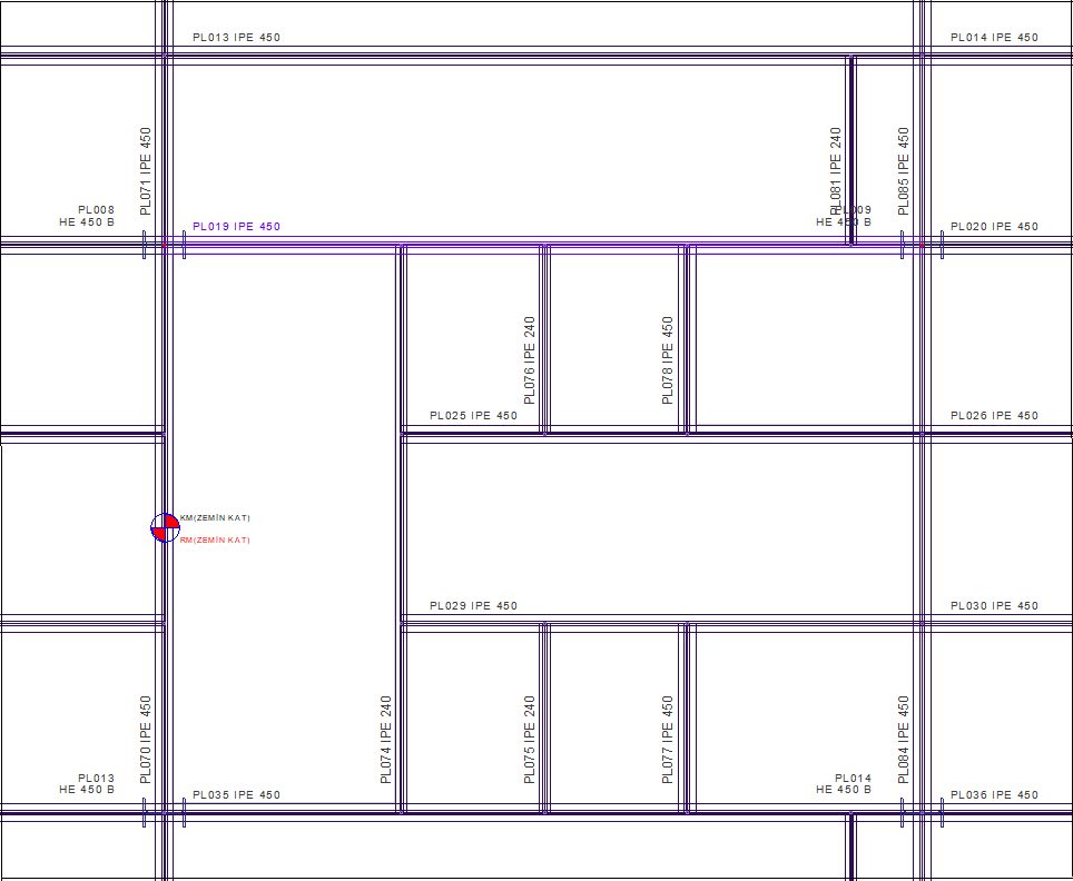
Design strength check of the steel beam named PL019 is done under the most unfavorable internal forces as a result of general analysis determined according to TBDY 2018 9.3.1.4. The material and section information of the beam is as follows:
Steel material: S275 Fy =275 N/mm 2 Fu =430 N/mm 2
Cross section: IPE 450
|
Ix = 33740 cm4 |
Iy = 1676 cm4 |
Jx = 66.87 cm4 |
Cw = 791000 cm6 |
|
Wex = 1500 cm3 |
Wpx = 1702 cm3 |
A= 98.80 cm4 |
|
|
d=450 mm |
h=378.8 mm |
bf = 190 mm |
tf = 14.6 mm |
|
tw = 9.4 mm |
ix=184.8 mm |
iy=41.2 mm |
|
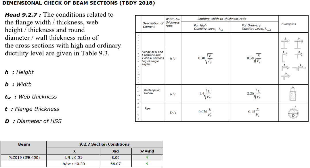
Control of Cross Section Conditions (TBDY 9.3.1)
It should be checked whether the flange width/thickness and web height/thickness values of the beam cross-section exceed λhd value given in Table 9.3 .
-
Cross section flange;
'%3e%3cg transform='translate(167%2c0)'%3e%3cg transform='translate(-13%2c0)'%3e%3cg transform='translate(0%2c-107)'%3e%3cuse xlink:href='%23MJMATHI-62' x='0' y='0'%3e%3c/use%3e%3cuse xlink:href='%23MJMAIN-2F' x='429' y='0'%3e%3c/use%3e%3cuse xlink:href='%23MJMATHI-74' x='930' y='0'%3e%3c/use%3e%3cuse xlink:href='%23MJMAIN-3D' x='1569' y='0'%3e%3c/use%3e%3cg transform='translate(2347%2c0)'%3e%3cg transform='translate(397%2c0)'%3e%3crect stroke='none' width='1889' height='60' x='0' y='220'%3e%3c/rect%3e%3cg transform='translate(60%2c602)'%3e%3cuse transform='scale(0.707)' xlink:href='%23MJMAIN-31'%3e%3c/use%3e%3cuse transform='scale(0.707)' xlink:href='%23MJMAIN-39' x='500' y='0'%3e%3c/use%3e%3cuse transform='scale(0.707)' xlink:href='%23MJMAIN-30' x='1001' y='0'%3e%3c/use%3e%3cuse transform='scale(0.707)' xlink:href='%23MJMAIN-2F' x='1501' y='0'%3e%3c/use%3e%3cuse transform='scale(0.707)' xlink:href='%23MJMAIN-32' x='2002' y='0'%3e%3c/use%3e%3c/g%3e%3cg transform='translate(315%2c-405)'%3e%3cuse transform='scale(0.707)' xlink:href='%23MJMAIN-31'%3e%3c/use%3e%3cuse transform='scale(0.707)' xlink:href='%23MJMAIN-34' x='500' y='0'%3e%3c/use%3e%3cuse transform='scale(0.707)' xlink:href='%23MJMAIN-2E' x='1001' y='0'%3e%3c/use%3e%3cuse transform='scale(0.707)' xlink:href='%23MJMAIN-36' x='1279' y='0'%3e%3c/use%3e%3c/g%3e%3c/g%3e%3c/g%3e%3cuse xlink:href='%23MJMAIN-3D' x='5032' y='0'%3e%3c/use%3e%3cg transform='translate(6089%2c0)'%3e%3cuse xlink:href='%23MJMAIN-36'%3e%3c/use%3e%3cuse xlink:href='%23MJMAIN-2E' x='500' y='0'%3e%3c/use%3e%3cuse xlink:href='%23MJMAIN-35' x='779' y='0'%3e%3c/use%3e%3cuse xlink:href='%23MJMAIN-31' x='1279' y='0'%3e%3c/use%3e%3c/g%3e%3c/g%3e%3c/g%3e%3c/g%3e%3c/g%3e%3c/svg%3e)
'%3e%3cg transform='translate(167%2c0)'%3e%3cg transform='translate(-13%2c0)'%3e%3cg transform='translate(0%2c3)'%3e%3cuse xlink:href='%23MJMAIN-36'%3e%3c/use%3e%3cuse xlink:href='%23MJMAIN-2E' x='500' y='0'%3e%3c/use%3e%3cuse xlink:href='%23MJMAIN-35' x='779' y='0'%3e%3c/use%3e%3cuse xlink:href='%23MJMAIN-31' x='1279' y='0'%3e%3c/use%3e%3cuse xlink:href='%23MJMAIN-3C' x='2057' y='0'%3e%3c/use%3e%3cg transform='translate(3114%2c0)'%3e%3cuse xlink:href='%23MJMAIN-30'%3e%3c/use%3e%3cuse xlink:href='%23MJMAIN-2E' x='500' y='0'%3e%3c/use%3e%3cuse xlink:href='%23MJMAIN-33' x='779' y='0'%3e%3c/use%3e%3c/g%3e%3cuse xlink:href='%23MJMAIN-221A' x='4393' y='0'%3e%3c/use%3e%3cg transform='translate(5227%2c0)'%3e%3cg transform='translate(120%2c0)'%3e%3crect stroke='none' width='2243' height='60' x='0' y='220'%3e%3c/rect%3e%3cg transform='translate(60%2c441)'%3e%3cuse transform='scale(0.707)' xlink:href='%23MJMAIN-32'%3e%3c/use%3e%3cuse transform='scale(0.707)' xlink:href='%23MJMAIN-30' x='500' y='0'%3e%3c/use%3e%3cuse transform='scale(0.707)' xlink:href='%23MJMAIN-30' x='1001' y='0'%3e%3c/use%3e%3cuse transform='scale(0.707)' xlink:href='%23MJMAIN-30' x='1501' y='0'%3e%3c/use%3e%3cuse transform='scale(0.707)' xlink:href='%23MJMAIN-30' x='2002' y='0'%3e%3c/use%3e%3cuse transform='scale(0.707)' xlink:href='%23MJMAIN-30' x='2502' y='0'%3e%3c/use%3e%3c/g%3e%3cg transform='translate(590%2c-405)'%3e%3cuse transform='scale(0.707)' xlink:href='%23MJMAIN-32'%3e%3c/use%3e%3cuse transform='scale(0.707)' xlink:href='%23MJMAIN-37' x='500' y='0'%3e%3c/use%3e%3cuse transform='scale(0.707)' xlink:href='%23MJMAIN-35' x='1001' y='0'%3e%3c/use%3e%3c/g%3e%3c/g%3e%3c/g%3e%3cuse xlink:href='%23MJMAIN-3D' x='7988' y='0'%3e%3c/use%3e%3cg transform='translate(9044%2c0)'%3e%3cuse xlink:href='%23MJMAIN-38'%3e%3c/use%3e%3cuse xlink:href='%23MJMAIN-2E' x='500' y='0'%3e%3c/use%3e%3cuse xlink:href='%23MJMAIN-30' x='779' y='0'%3e%3c/use%3e%3cuse xlink:href='%23MJMAIN-39' x='1279' y='0'%3e%3c/use%3e%3c/g%3e%3c/g%3e%3c/g%3e%3c/g%3e%3c/g%3e%3c/svg%3e) koşulu sağlar.
koşulu sağlar.
-
Cross-section web;
'%3e%3cg transform='translate(167%2c0)'%3e%3cg transform='translate(-13%2c0)'%3e%3cg transform='translate(0%2c71)'%3e%3cuse xlink:href='%23MJMATHI-43' x='0' y='0'%3e%3c/use%3e%3cuse transform='scale(0.707)' xlink:href='%23MJMATHI-61' x='1011' y='-213'%3e%3c/use%3e%3cuse xlink:href='%23MJMAIN-3D' x='1467' y='0'%3e%3c/use%3e%3cg transform='translate(2246%2c0)'%3e%3cg transform='translate(397%2c0)'%3e%3crect stroke='none' width='2774' height='60' x='0' y='220'%3e%3c/rect%3e%3cg transform='translate(873%2c537)'%3e%3cuse transform='scale(0.707)' xlink:href='%23MJMATHI-50' x='0' y='0'%3e%3c/use%3e%3cg transform='translate(454%2c-107)'%3e%3cuse transform='scale(0.5)' xlink:href='%23MJMATHI-75' x='0' y='0'%3e%3c/use%3e%3cuse transform='scale(0.5)' xlink:href='%23MJMATHI-63' x='572' y='0'%3e%3c/use%3e%3c/g%3e%3c/g%3e%3cg transform='translate(60%2c-457)'%3e%3cuse transform='scale(0.707)' xlink:href='%23MJMAIN-3A6' x='0' y='0'%3e%3c/use%3e%3cuse transform='scale(0.5)' xlink:href='%23MJMATHI-63' x='1021' y='-213'%3e%3c/use%3e%3cuse transform='scale(0.707)' xlink:href='%23MJMAIN-28' x='1129' y='0'%3e%3c/use%3e%3cg transform='translate(1073%2c0)'%3e%3cuse transform='scale(0.707)' xlink:href='%23MJMATHI-46' x='0' y='0'%3e%3c/use%3e%3cuse transform='scale(0.5)' xlink:href='%23MJMATHI-79' x='910' y='-213'%3e%3c/use%3e%3c/g%3e%3cuse transform='scale(0.707)' xlink:href='%23MJMATHI-41' x='2613' y='0'%3e%3c/use%3e%3cuse transform='scale(0.707)' xlink:href='%23MJMAIN-29' x='3364' y='0'%3e%3c/use%3e%3c/g%3e%3c/g%3e%3c/g%3e%3c/g%3e%3c/g%3e%3c/g%3e%3c/g%3e%3c/svg%3e)
'%3e%3cg transform='translate(167%2c0)'%3e%3cg transform='translate(-13%2c0)'%3e%3cg transform='translate(0%2c-50)'%3e%3cuse xlink:href='%23MJMATHI-50' x='0' y='0'%3e%3c/use%3e%3cg transform='translate(642%2c-150)'%3e%3cuse transform='scale(0.707)' xlink:href='%23MJMATHI-75' x='0' y='0'%3e%3c/use%3e%3cuse transform='scale(0.707)' xlink:href='%23MJMATHI-63' x='572' y='0'%3e%3c/use%3e%3c/g%3e%3cuse xlink:href='%23MJMAIN-3D' x='1731' y='0'%3e%3c/use%3e%3cuse xlink:href='%23MJMAIN-30' x='2787' y='0'%3e%3c/use%3e%3c/g%3e%3c/g%3e%3c/g%3e%3c/g%3e%3c/svg%3e)
The result of the analysis was accepted as 0 because the axial force value was low.
'%3e%3cg transform='translate(167%2c0)'%3e%3cg transform='translate(-13%2c0)'%3e%3cg transform='translate(0%2c110)'%3e%3cuse xlink:href='%23MJMATHI-43' x='0' y='0'%3e%3c/use%3e%3cuse transform='scale(0.707)' xlink:href='%23MJMATHI-61' x='1011' y='-213'%3e%3c/use%3e%3cuse xlink:href='%23MJMAIN-3D' x='1467' y='0'%3e%3c/use%3e%3cg transform='translate(2246%2c0)'%3e%3cg transform='translate(397%2c0)'%3e%3crect stroke='none' width='4760' height='60' x='0' y='220'%3e%3c/rect%3e%3cuse transform='scale(0.707)' xlink:href='%23MJMAIN-30' x='3116' y='624'%3e%3c/use%3e%3cg transform='translate(60%2c-457)'%3e%3cuse transform='scale(0.707)' xlink:href='%23MJMAIN-30'%3e%3c/use%3e%3cuse transform='scale(0.707)' xlink:href='%23MJMAIN-2E' x='500' y='0'%3e%3c/use%3e%3cuse transform='scale(0.707)' xlink:href='%23MJMAIN-39' x='779' y='0'%3e%3c/use%3e%3cuse transform='scale(0.707)' xlink:href='%23MJMAIN-30' x='1279' y='0'%3e%3c/use%3e%3cuse transform='scale(0.707)' xlink:href='%23MJMAIN-28' x='1779' y='0'%3e%3c/use%3e%3cg transform='translate(1534%2c0)'%3e%3cuse transform='scale(0.707)' xlink:href='%23MJMAIN-32'%3e%3c/use%3e%3cuse transform='scale(0.707)' xlink:href='%23MJMAIN-37' x='500' y='0'%3e%3c/use%3e%3cuse transform='scale(0.707)' xlink:href='%23MJMAIN-35' x='1001' y='0'%3e%3c/use%3e%3c/g%3e%3cuse transform='scale(0.707)' xlink:href='%23MJMAIN-2217' x='3670' y='0'%3e%3c/use%3e%3cg transform='translate(2949%2c0)'%3e%3cuse transform='scale(0.707)' xlink:href='%23MJMAIN-39'%3e%3c/use%3e%3cuse transform='scale(0.707)' xlink:href='%23MJMAIN-38' x='500' y='0'%3e%3c/use%3e%3cuse transform='scale(0.707)' xlink:href='%23MJMAIN-38' x='1001' y='0'%3e%3c/use%3e%3cuse transform='scale(0.707)' xlink:href='%23MJMAIN-30' x='1501' y='0'%3e%3c/use%3e%3c/g%3e%3cuse transform='scale(0.707)' xlink:href='%23MJMAIN-29' x='6173' y='0'%3e%3c/use%3e%3c/g%3e%3c/g%3e%3c/g%3e%3cuse xlink:href='%23MJMAIN-3D' x='7802' y='0'%3e%3c/use%3e%3cuse xlink:href='%23MJMAIN-30' x='8858' y='0'%3e%3c/use%3e%3cuse xlink:href='%23MJMAIN-3C' x='9637' y='0'%3e%3c/use%3e%3cg transform='translate(10693%2c0)'%3e%3cuse xlink:href='%23MJMAIN-30'%3e%3c/use%3e%3cuse xlink:href='%23MJMAIN-2E' x='500' y='0'%3e%3c/use%3e%3cuse xlink:href='%23MJMAIN-31' x='779' y='0'%3e%3c/use%3e%3cuse xlink:href='%23MJMAIN-32' x='1279' y='0'%3e%3c/use%3e%3cuse xlink:href='%23MJMAIN-35' x='1780' y='0'%3e%3c/use%3e%3c/g%3e%3c/g%3e%3c/g%3e%3c/g%3e%3c/g%3e%3c/svg%3e)
'%3e%3cg transform='translate(167%2c0)'%3e%3cg transform='translate(-13%2c0)'%3e%3cuse xlink:href='%23MJMATHI-68' x='0' y='0'%3e%3c/use%3e%3cuse xlink:href='%23MJMAIN-2F' x='576' y='0'%3e%3c/use%3e%3cg transform='translate(1077%2c0)'%3e%3cuse xlink:href='%23MJMATHI-74' x='0' y='0'%3e%3c/use%3e%3cuse transform='scale(0.707)' xlink:href='%23MJMATHI-77' x='511' y='-213'%3e%3c/use%3e%3c/g%3e%3cuse xlink:href='%23MJMAIN-3D' x='2322' y='0'%3e%3c/use%3e%3cg transform='translate(3101%2c0)'%3e%3cg transform='translate(397%2c0)'%3e%3crect stroke='none' width='1732' height='60' x='0' y='220'%3e%3c/rect%3e%3cg transform='translate(60%2c441)'%3e%3cuse transform='scale(0.707)' xlink:href='%23MJMAIN-33'%3e%3c/use%3e%3cuse transform='scale(0.707)' xlink:href='%23MJMAIN-37' x='500' y='0'%3e%3c/use%3e%3cuse transform='scale(0.707)' xlink:href='%23MJMAIN-38' x='1001' y='0'%3e%3c/use%3e%3cuse transform='scale(0.707)' xlink:href='%23MJMAIN-2E' x='1501' y='0'%3e%3c/use%3e%3cuse transform='scale(0.707)' xlink:href='%23MJMAIN-38' x='1780' y='0'%3e%3c/use%3e%3c/g%3e%3cg transform='translate(413%2c-405)'%3e%3cuse transform='scale(0.707)' xlink:href='%23MJMAIN-39'%3e%3c/use%3e%3cuse transform='scale(0.707)' xlink:href='%23MJMAIN-2E' x='500' y='0'%3e%3c/use%3e%3cuse transform='scale(0.707)' xlink:href='%23MJMAIN-34' x='779' y='0'%3e%3c/use%3e%3c/g%3e%3c/g%3e%3c/g%3e%3cuse xlink:href='%23MJMAIN-3D' x='5629' y='0'%3e%3c/use%3e%3cg transform='translate(6685%2c0)'%3e%3cuse xlink:href='%23MJMAIN-34'%3e%3c/use%3e%3cuse xlink:href='%23MJMAIN-30' x='500' y='0'%3e%3c/use%3e%3cuse xlink:href='%23MJMAIN-2E' x='1001' y='0'%3e%3c/use%3e%3cuse xlink:href='%23MJMAIN-33' x='1279' y='0'%3e%3c/use%3e%3cuse xlink:href='%23MJMAIN-30' x='1780' y='0'%3e%3c/use%3e%3c/g%3e%3c/g%3e%3c/g%3e%3c/g%3e%3c/svg%3e)
'%3e%3cg transform='translate(167%2c0)'%3e%3cg transform='translate(-13%2c0)'%3e%3cg transform='translate(0%2c3)'%3e%3cuse xlink:href='%23MJMAIN-34'%3e%3c/use%3e%3cuse xlink:href='%23MJMAIN-30' x='500' y='0'%3e%3c/use%3e%3cuse xlink:href='%23MJMAIN-2E' x='1001' y='0'%3e%3c/use%3e%3cuse xlink:href='%23MJMAIN-33' x='1279' y='0'%3e%3c/use%3e%3cuse xlink:href='%23MJMAIN-30' x='1780' y='0'%3e%3c/use%3e%3cuse xlink:href='%23MJMAIN-3C' x='2558' y='0'%3e%3c/use%3e%3cg transform='translate(3614%2c0)'%3e%3cuse xlink:href='%23MJMAIN-32'%3e%3c/use%3e%3cuse xlink:href='%23MJMAIN-2E' x='500' y='0'%3e%3c/use%3e%3cuse xlink:href='%23MJMAIN-34' x='779' y='0'%3e%3c/use%3e%3cuse xlink:href='%23MJMAIN-35' x='1279' y='0'%3e%3c/use%3e%3c/g%3e%3cuse xlink:href='%23MJMAIN-221A' x='5394' y='0'%3e%3c/use%3e%3cg transform='translate(6228%2c0)'%3e%3cg transform='translate(120%2c0)'%3e%3crect stroke='none' width='2243' height='60' x='0' y='220'%3e%3c/rect%3e%3cg transform='translate(60%2c441)'%3e%3cuse transform='scale(0.707)' xlink:href='%23MJMAIN-32'%3e%3c/use%3e%3cuse transform='scale(0.707)' xlink:href='%23MJMAIN-30' x='500' y='0'%3e%3c/use%3e%3cuse transform='scale(0.707)' xlink:href='%23MJMAIN-30' x='1001' y='0'%3e%3c/use%3e%3cuse transform='scale(0.707)' xlink:href='%23MJMAIN-30' x='1501' y='0'%3e%3c/use%3e%3cuse transform='scale(0.707)' xlink:href='%23MJMAIN-30' x='2002' y='0'%3e%3c/use%3e%3cuse transform='scale(0.707)' xlink:href='%23MJMAIN-30' x='2502' y='0'%3e%3c/use%3e%3c/g%3e%3cg transform='translate(590%2c-405)'%3e%3cuse transform='scale(0.707)' xlink:href='%23MJMAIN-32'%3e%3c/use%3e%3cuse transform='scale(0.707)' xlink:href='%23MJMAIN-37' x='500' y='0'%3e%3c/use%3e%3cuse transform='scale(0.707)' xlink:href='%23MJMAIN-35' x='1001' y='0'%3e%3c/use%3e%3c/g%3e%3c/g%3e%3c/g%3e%3cuse xlink:href='%23MJMAIN-28' x='8711' y='0'%3e%3c/use%3e%3cuse xlink:href='%23MJMAIN-31' x='9100' y='0'%3e%3c/use%3e%3cuse xlink:href='%23MJMAIN-2212' x='9823' y='0'%3e%3c/use%3e%3cg transform='translate(10824%2c0)'%3e%3cuse xlink:href='%23MJMAIN-30'%3e%3c/use%3e%3cuse xlink:href='%23MJMAIN-2E' x='500' y='0'%3e%3c/use%3e%3cuse xlink:href='%23MJMAIN-39' x='779' y='0'%3e%3c/use%3e%3cuse xlink:href='%23MJMAIN-33' x='1279' y='0'%3e%3c/use%3e%3c/g%3e%3cg transform='translate(12604%2c0)'%3e%3cuse xlink:href='%23MJMATHI-43' x='0' y='0'%3e%3c/use%3e%3cuse transform='scale(0.707)' xlink:href='%23MJMATHI-61' x='1011' y='-213'%3e%3c/use%3e%3c/g%3e%3cuse xlink:href='%23MJMAIN-29' x='13794' y='0'%3e%3c/use%3e%3cuse xlink:href='%23MJMAIN-3D' x='14461' y='0'%3e%3c/use%3e%3cg transform='translate(15517%2c0)'%3e%3cuse xlink:href='%23MJMAIN-36'%3e%3c/use%3e%3cuse xlink:href='%23MJMAIN-36' x='500' y='0'%3e%3c/use%3e%3cuse xlink:href='%23MJMAIN-2E' x='1001' y='0'%3e%3c/use%3e%3cuse xlink:href='%23MJMAIN-30' x='1279' y='0'%3e%3c/use%3e%3cuse xlink:href='%23MJMAIN-37' x='1780' y='0'%3e%3c/use%3e%3c/g%3e%3c/g%3e%3c/g%3e%3c/g%3e%3c/g%3e%3c/svg%3e) koşulu sağlar.
koşulu sağlar.
The control of the cross-section conditions is done according to TBDY 2018 Table 9.3 in the steel beam report and summarized in tabular form.
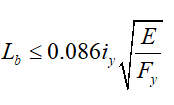
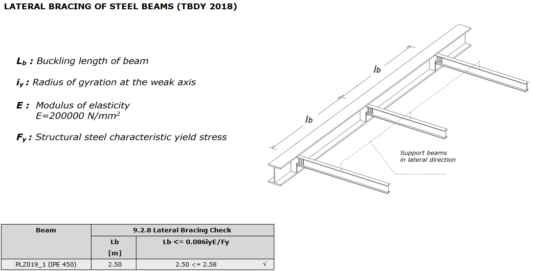
Lateral Supporting of Beam Flange
The longest unsupported beam segment in the lateral direction is Lb = 2.0 m. According to TBDY 2018 9.2.8.1(a), the distance between the points where the lower and upper ends of special beams are supported, Lb should meet the following condition.
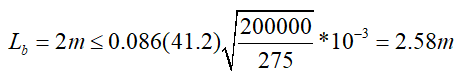
It provides the condition. In the steel beam report, the control results are given in tables.
Flexural Moment Strength
While checking the beam design flexural moment strength, since the lateral supported lengths are different, station-by-station should be done for each section. For the convenience of manual check, it will be done for the section Lb = 0.75 m, which is exposed to the most unfavorable flexural moment.
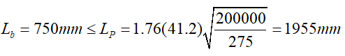
Because of the condition, the characteristic of flexural moment strength is determined according to yield limit condition. According to the CYTHYE equation 9.2, the check is done as follows:
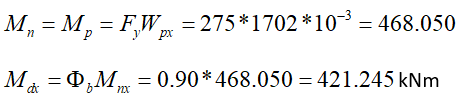
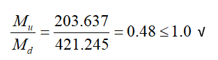
As a result of the analysis, the required flexural moment strength obtained as a result of 1.2G+Q-Ex-0.3Ey+0.2S+0.3Ez loading is Mu = 203.637 kNm.
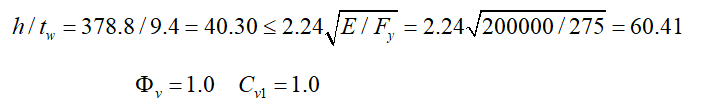
Shear Strength of The Beam
According to ÇYTHYE 10.2.1(a) in I-cross section with double symmetry axes,
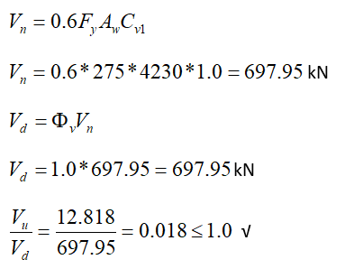
With the load combination Q-Ex-0.3ey + 1.2G + 0.2S + 0.3ez, required shear force is determined as Vu = 12818 kN. It has been shown above that the cross-sectional capacity is sufficient.
Next Topic