
Symbols
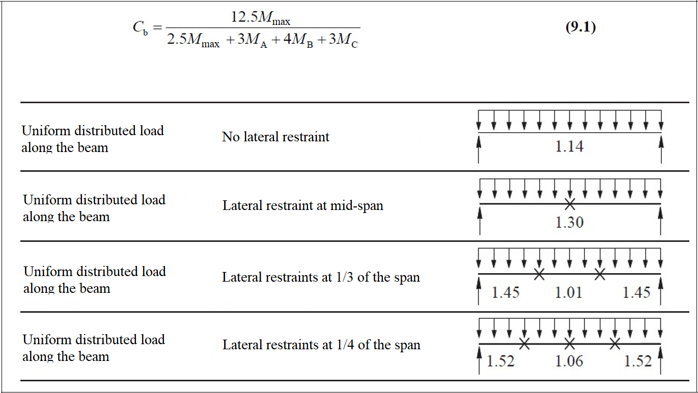
Cb : The lateral-torsional buckling modification factor defined by Equation 9.1
E: Modulus of elasticity of steel = 29,000 ksi (200 000 MPa)
Fy : Specified minimum yield stress of the type of steel being used, ksi
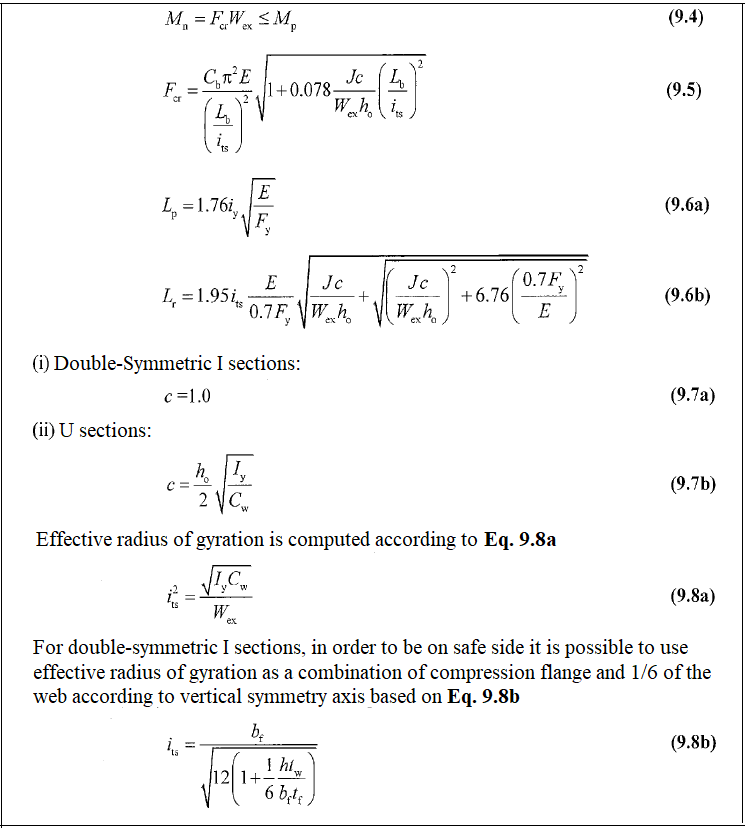
Its : Effective radius of gyration
J: Torsion constant
ho : Distance between the flange centroids, in. (mm)
Lb : Length between points that are either braced against the lateral displacement of the compression flange or braced against twist of the cross-section, in. (mm)
Lp : The limiting laterally unbraced length for the limit state of yielding, in. (mm)
Lr : The limiting unbraced length for the limit state of inelastic lateral-torsional buckling, in. (mm),
Mn : The nominal flexural strength
Mp : Plastic flexural moment
Wpx : Plastic section modulus is taken about the x-axis in.3 (mm3)
Wex : Elastic section modulus is taken about the x-axis, in.3 (mm3)
Bending Member Definition
-
These are elements that are under the effect of a simple flexural moment around their principal axes. For the elements that are under the effect of the simple flexural moment, the loads should be acting in the plane parallel to the principal axis passing through the shear center or the element should be supported against torsion at the load application points and supports.
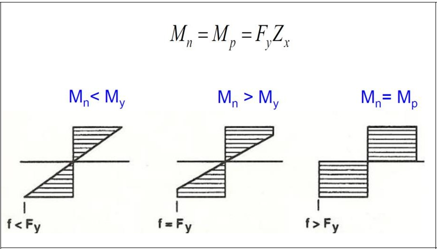
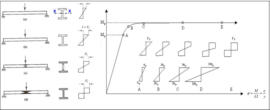
Yielding Limit State
-
It is a situation where the cross-section of the beam is dimensioned to remain stable until it becomes plasticize under the effect of flexure if the local buckling of the compression flange and the lateral twisting buckling is prevented. In this case, the characteristic moment strength can be taken equal to the plastic moment strength.
-
The yield moment is the moment value when the uppermost fiber of the section under the effect of flexural moment reaches the yield stress.
-
Plastic Moment is the moment value when all fibers of the section under the effect of flexural moment reach the yield stress.
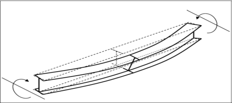
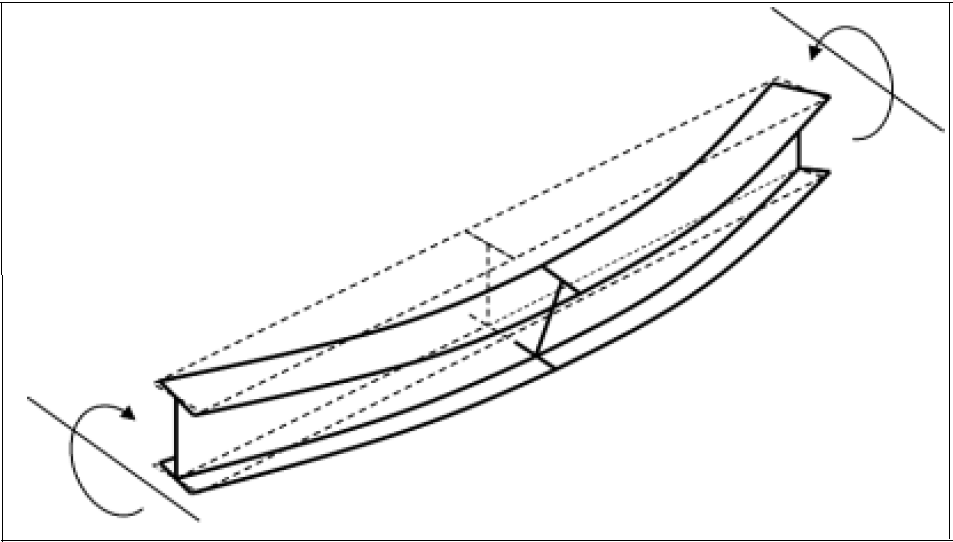
Lateral Torsional Buckling Limit State
-
The part of the beam that is under the compression acts like an axially loaded compression bar. If the stability of the compression flange is not sufficient, the beam section cannot reach its full flexural capacity. In this case, similar to the compression elements; General buckling or loss of stability in cross-sectional parts that may occur with local buckling determines the collapse limit state. This type of buckling of the compression flange is called lateral torsion buckling.
Design with ÇYTHYE 2018
9.2.1 Yielding Limit State
-
The characteristic flexural moment strength Mn for the yield limit state is calculated by equation 9.2.

9.2.2 Lateral Torsional Buckling Limit State
-
For the lateral torsion buckling limit state, the characteristic bending moment strength is divided for 3 different failure limit conditions, which are the laterally unbraced length of the compression part Mn, the changes that occur due to Lb and the effect of the moment correction coefficient Cb are shown in the figure below:
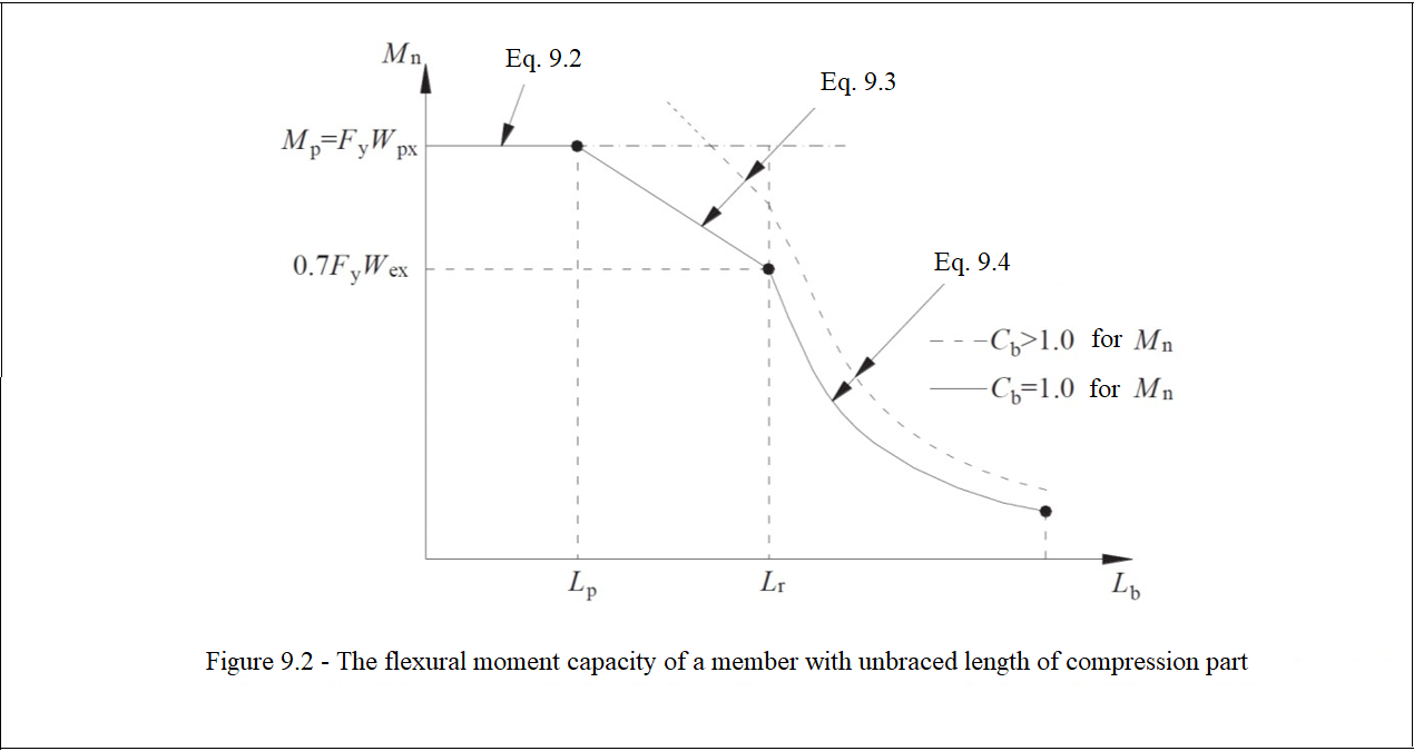
a) If Lb ≤ Lp, this limit situation need not be taken into account.
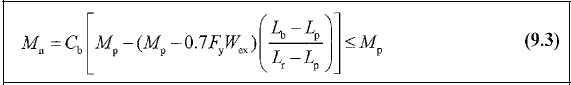
b) If Lp <Lb ≤ Lr, the characteristic flexural moment strength Mn is calculated by equation 9.3.
c) If Lb > Lr, the characteristic flexural moment strength Mn shall be determined by equation 9.4.
-
Cb Coefficient: It is the contribution of flexural moment distribution along the length between the supporting points by the lateral stability connection for the case of lateral-torsional buckling limit.
Design for Combined Forces
-
The strength calculation is made by taking into account the combined stresses created in the members under a flexural moment and axial force.
-
Computational details are available at Design of Steel Members for Combined Forces.
Next Topic