
How does ideCAD design Column/Beam splice connection according to AISC 360-16?
-
Column/Beam splice connection design limit states and geometry checks are done automatically according to AISC 360-16.
-
The block shear limit state is checked automatically according to AISC 360-16.
Download ideCAD for Connection Design with AISC 360-16
Symbols
Ab: Non-threaded bolt web characteristic cross-sectional area
Ag: Gross area
An: Net cross-section area
Ae: Effective net cross-sectional area
Avg: Gross area under shear stress
Anv: Net area under shear stress
Ant: Net area under tensile stress
d: Characteristic diameter of the stem of the bolt (the diameter of the non-threaded stem of the bolt)
dh: Bolt hole diameter
Fy: Structural steel characteristic yield strength
Fu: Structural steel characteristic tensile strength
s: Distance between bolt-hole centers
Lc: The clear distance between bolt holes
Le: The distance from the center of the bolt hole to the edge of the assembled element
Leh: The horizontal distance from the center of the bolt hole to the edge of the assembled element
Lev: The vertical distance from the center of the bolt hole to the edge of the assembled element
t: Plate thickness
Rn: Characteristic strength
Ubs: A coefficient considering the spread of tensile stresses
Connection Geometry
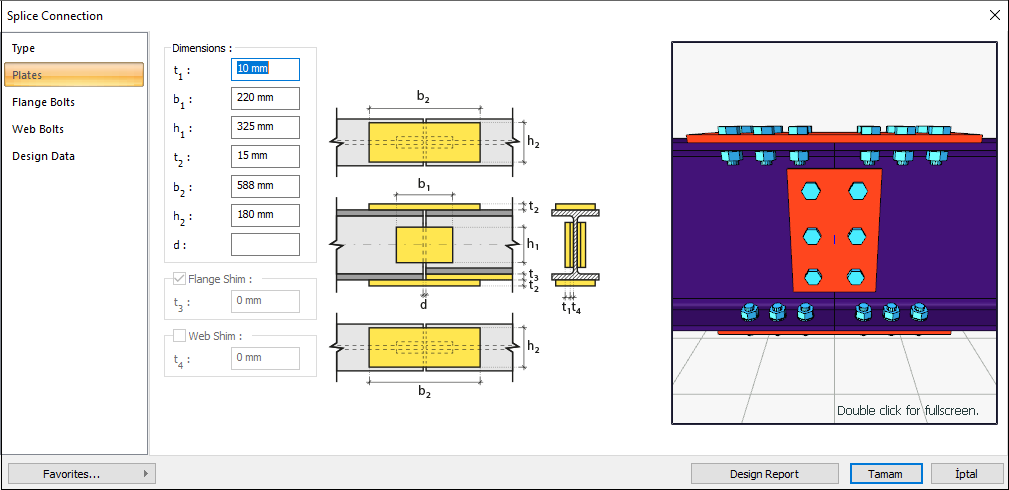
GEOMETRY CHECKS
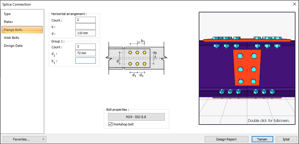
Bolt Spacing at Flange
The distance between the centers of bolts is checked per AISC 360-16.
|
smin ≥ 3d |
AISC 360-16 J3.3 |
|
|
|
s |
72 mm |
|
|
|
d |
24 mm |
s =72 mm > smin = 3*24=72 mm |
√ |
Horizontal Edge Distance at Flange
The distance from the center of the hole to the edge of the connected part in the horizontal direction is checked per AISC 360-16.
|
Leh ≥ Le-min |
AISC 360-16 J3.4 |
|
|
|
Leh |
75 mm |
Leh ≥ 2d = 2 * 24 = 48 mm conformity check for application |
√ |
|
Le-min |
30 mm |
Minimum distance check according to Table J3.4 |
√ |
Vertical Edge Distance at Flange
The distance from the center of the hole to the edge of the connected part in the vertical direction is checked per AISC 360-16.
|
Lev ≥ Le-min |
AISC 360-16 J3.4 |
|
|
|
Lev |
35 mm |
|
|
|
Le- min |
30 mm |
Minimum distance check according to AISC 360-16 Table J3.4 |
√ |
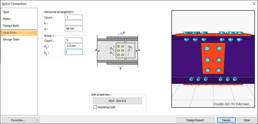
Bolt Spacing at Web
The distance between the centers of bolts is checked per AISC 360-16.
|
smin ≥ 3d |
AISC 360-16 J3.3 |
|
|
|
s |
113 mm |
|
|
|
d |
24 mm |
s =113 mm > smin = 3*24=72 mm |
√ |
Horizontal Edge Distance at Web
The distance from the center of the hole to the edge of the connected part in the horizontal direction is checked per AISC 360-16.
|
Leh ≥ L e-min |
AISC 360-16 J3.4 |
|
|
|
Leh |
55 mm |
Leh ≥ 2d = 2 * 24 = 48 mm conformity check for application |
√ |
|
Le-min |
30 mm |
Minimum distance check according to Table J3.4 |
√ |
Vertical Edge Distance at Web
The distance from the center of the hole to the edge of the connected part in the vertical direction is checked per AISC 360-16.
|
Lev ≥ Le-min |
AISC 360-16 J3.3 |
|
|
|
Lev |
49.5 mm |
L eh ≥ 2d = 2 * 24 = 48 mm conformity check for application |
√ |
|
Le-min |
30 mm |
Minimum distance check according to Table J3.4 |
√ |
STRENGTH CHECKS
Bolt Shear at Flange
The calculation is made using the Elastic method, one of the methods selected in the steel analysis settings tab. In this check, the operation is performed on half of the symmetry axis and is calculated to form a force pair with the required force.
|
Ab |
|
AISC 360-16 J3-1 |
|
Fn |
|
|
|
Rn |
|
|
|
ΦRn |
|
|
|
Required |
Ready |
Rate |
Control |
|---|---|---|---|
|
425.018 kN |
732.87 kN |
0.580 |
√ |
Bolt Bearing on Flange Plate
The bearing strength limit states of the connection plate, which are “shear tear out” and “ovalization of bolt hole” for both end and inner bolts, are checked according to AISC 360-16.
|
dh |
24+3=27 mm |
|
|
Lc,edge |
|
|
|
Rn |
|
AISC 360-16 J3-6a |
|
Rn-edge |
|
|
|
Lc,spacing |
|
|
|
Rn-spacing |
|
|
|
Rn |
|
|
|
ΦRn |
|
|
|
Required |
Available |
Ratio |
Control |
|---|---|---|---|
|
425.018 kN |
1341.36 kN |
0.317 |
√ |
Bolt Bearing on Beam Flange
The bearing strength limit states of the connection plate, which are “shear tear out” and “ovalization of bolt hole” for both end and inner bolts, are checked according to AISC 360-16.
|
dh |
24+3=27 mm |
|
|
Lc,edge |
|
|
|
Rn |
|
AISC 360-16 J3-6a |
|
Rn-edge |
|
|
|
Lc,spacing |
|
|
|
Rn-spacing |
|
|
|
Rn |
|
|
|
ΦRn |
|
|
|
Required |
Available |
Ratio |
Control |
|---|---|---|---|
|
418.114 kN |
1305.591 kN |
0.320 |
√ |
Flange Plate Tension Yield
The yield limit state of the connection plate subjected to tension is checked according to AISC 360-16.
|
Ag |
|
|
|
Fy |
235 N/mm2 |
|
|
Rn |
|
AISC 360-16 J4-1 |
|
ΦRn |
|
|
|
Required |
Available |
Ratio |
Control |
|---|---|---|---|
|
301.881 kN |
571.92 kN |
0.529 |
√ |
Flange Plate Tension Rupture
The limit state of the flange plate tension rupture is checked according to AISC 360-16.
|
An |
|
|
|
Ae |
|
|
|
Fu |
360 N/mm2 |
|
|
U |
1.00 |
|
|
Rn |
|
AISC 360-16 J4-2 |
|
ΦRn |
|
|
|
Required |
Available |
Ratio |
Control |
|---|---|---|---|
|
301.881 kN |
494.1 kN |
0.611 |
√ |
Flange Plate Block Shear
The block shear limit state is checked according to AISC 360-16. All block shear modes combined with tensile failure on one plane and shear failure on a perpendicular plane are checked according to AISC 360-16.
|
Ag |
|
|
|
Anv |
|
|
|
Ant |
|
|
|
Fy |
235 N/mm2 |
|
|
Fu |
360 N/mm2 |
|
|
Ubs |
1.0 |
|
|
|
|
|
|
Rn |
|
AISC 360-16 J4-5 |
|
ΦRn |
|
|
|
Required |
Available |
Ratio |
Control |
|---|---|---|---|
|
301.881 kN |
860.828 kN |
0.351 |
√ |
Beam Flange Block Shear
The block shear limit state is checked according to AISC 360-16. All block shear modes combined with tensile failure on one plane and shear failure on a perpendicular plane are checked according to AISC 360-16.
|
Ag |
|
|
|
Anv |
|
|
|
Ant |
|
|
|
Fy |
235 N/mm2 |
|
|
Fu |
360 N/mm2 |
|
|
Ubs |
1.0 |
|
|
|
|
|
|
Rn |
|
AISC 360-16 J4-5 |
|
ΦRn |
|
|
|
Required |
Available |
Ratio |
Control |
|---|---|---|---|
|
301.881 kN |
837.867 kN |
0.360 |
√ |
Flange Plate Compression Yield
The yield limit state of the connection plate subjected to compression is checked according to AISC 360-16.
|
K |
0.65 |
|
|
L |
150 mm |
|
|
r |
4.33 mm |
|
|
KL / r |
22.52 |
|
|
Fy |
235 N/mm2 |
|
|
Ag |
|
|
|
Rn |
|
AISC 360-16 J4-6 |
|
ΦRn |
|
|
|
Required |
Available |
Ratio |
Control |
|---|---|---|---|
|
418.114 kN |
571.05 kN |
0.732 |
√ |
Bolt Shear at Web
The shear limit state of end plate bolts is checked according to AISC 360-16.
|
Ab |
|
|
|
Fn |
|
|
|
Rn |
|
AISC 360-16 J3-1 |
|
ΦRn |
|
|
|
Required |
Available |
Ratio |
Control |
|---|---|---|---|
|
0.031 kN |
244.29 kN |
0.00013 |
√ |
Bolt Bearing on Web Plate
Bearing strength limit states of the connection plate that are “shear tear out” and “ovalization of bolt hole” for both end and inner bolts are checked according to AISC 360-16.
|
dh |
24+3=27 mm |
|
|
Lc,edge |
|
|
|
Rn |
|
AISC 360-16 J3-6a |
|
Rn-edge |
|
|
|
Rn |
|
|
|
ΦRn |
|
|
|
Required |
Available |
Ratio |
Control |
|---|---|---|---|
|
0.031 kN |
233.28 kN |
0.0001 |
√ |
Bolt Bearing on Beam Web
Bearing strength limit states of the connection plate that are “shear tear out” and “ovalization of bolt hole” for both end and inner bolts are checked according to AISC 360-16.
|
dh |
24+3=27 mm |
|
|
Lc,edge |
|
|
|
Rn |
|
AISC 360-16 J3-6a |
|
Rn-edge |
|
|
|
Rn |
|
|
|
ΦRn |
|
|
|
Required |
Available |
Ratio |
Control |
|---|---|---|---|
|
0.031 kN |
126.392 kN |
0.00024 |
√ |
Web Plate Shear Yield
The shear strength of connecting elements in shear is the minimum value obtained according to the limit states of shear yielding and shear rupture. Shear yielding is checked according to AISC 360-16.
|
Ag |
|
|
|
Fy |
235 N/mm2 |
|
|
Rn |
|
AISC 360-16 J4-3 |
|
ΦRn |
|
|
|
Required |
Available |
Ratio |
Control |
|---|---|---|---|
|
0.075 kN |
916.5 kN |
0.0001 |
√ |
Web Plate Shear Rupture
The shear strength of connecting elements in shear is the minimum value obtained according to the limit states of shear yielding and shear rupture. Shear rupture is checked according to AISC 360-16.
|
Anv |
|
|
|
Ae |
|
|
|
Fu |
360 N/mm2 |
|
|
Rn |
|
AISC 360-16 J4-4 |
|
ΦRn |
|
|
|
Required |
Available |
Ratio |
Control |
|---|---|---|---|
|
0.075 kN |
771.12 kN |
0.0001 |
√ |
Beam Shear Rupture
The shear strength of connecting elements in shear is the minimum value obtained according to the limit states of shear yielding and shear rupture. Shear rupture is checked according to AISC 360-16.
|
Anv |
|
|
|
Ae |
|
|
|
Fu |
360 N/mm2 |
|
|
Rn |
|
AISC 360-16 J4-4 |
|
ΦRn |
|
|
|
Required |
Available |
Ratio |
Control |
|---|---|---|---|
|
0.075 kN |
552.76 kN |
0.0001 |
√ |
Web Plate Block Shear
The block shear limit state is checked according to AISC 360-16. All block shear modes combined with tensile failure on one plane and shear failure on a perpendicular plane are checked according to AISC 360-16.
|
Ag |
|
|
|
Anv |
|
|
|
Ant |
|
|
|
Fy |
235 N/mm2 |
|
|
Fu |
360 N/mm2 |
|
|
Ubs |
1.0 |
|
|
|
|
|
|
Rn |
|
AISC 360-16 J4-5 |
|
ΦRn |
|
|
|
Required |
Available |
Ratio |
Control |
|---|---|---|---|
|
0.075 kN |
801.38 kN |
0.0001 |
√ |
Download ideCAD for Connection Design
Next Topic