-
Modal contribution multipliers are calculated and reported automatically.
-
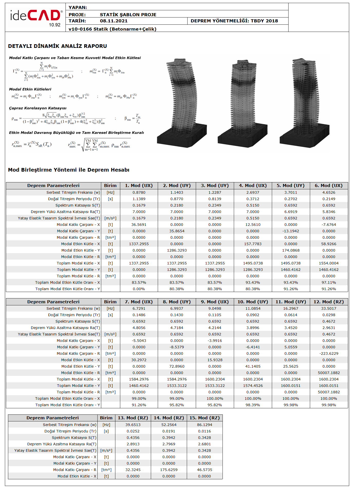
Base Shear Force Modal Effective Masses are automatically calculated and reported.
-
Base Shear Force Modal Effective Masses are automatically calculated and reported.
ICONS
m i = total mass of the i th floor
m iθ = mass moment of inertia of the i th floor
m ixn (X) = (X) the i'th floor modal effective mass m of the nth natural vibration mode of the building in the x-axis direction for the earthquake direction iyn (X) = (X) earthquake direction, i'th floor modal effective mass belonging to the nth natural vibration mode of the building in the y-axis direction
m iθn (X) = (X) the nth natural vibration of the building around the z-axis for the earthquake directionth floor modal effective mass moment of inertia
m j (S) = Single mass acting at typical finite element node j
m t = Total mass of the upper section of the building above the basement floors
m txn (X) = (X) the base shear force of the nth vibration mode of the building in the x-axis direction for the earthquake direction modal effective mass
m tyn (Y) = (Y) base shear force modal effective mass of the building in the y-axis direction for the earthquake direction
Φ i(X)n = nth natural vibration mode shape amplitude in the earthquake direction at the ith floor (X)
Φ ixn = nth natural vibration mode shape amplitude in the x-axis direction at the i'th floor
Φiyn = nth natural vibration mode shape amplitude in the y-axis direction at the i'th floor
Φ iθn = nth natural vibration mode shape amplitude as rotation around the z-axis at the i'th floor
Γ n (X) = (X) for the earthquake direction, modal contribution factor for the nth vibration mode
Modal calculation parameters ( Modal Contribution Multiplier and Base Shear Force Modal Effective Mass ) defined in 4B.1.4 according to TBDY 4B.1.1 are calculated only according to the earthquake direction taken into consideration and the information obtained from the free vibration calculation of the carrier system, and Mode Combination They are the quantities used in the Method of Addition and the Method of Addition in the Time Domain . Under this heading, the use of Mod Combination Method will be explained.
Modal calculation parameters are defined below only for (X) horizontal earthquake direction. The same parameters can be defined similarly for the earthquake direction (Y) perpendicular to (X).
As the degrees of freedom of the carrier system in the definition of the modal calculation parameters:
In case the floor slabs are modeled as rigid diaphragms according to TBDY 4B.1.3(a) , the displacements defined in the x and y horizontal directions at the center of mass of any ith floor slab and the rotation around the vertical axis passing through the floor mass center are taken into account and the corresponding degrees of freedom are taken into account. The storey mass mi is defined by the storey mass moment of inertia miθ . In case floor slabs are not taken as rigid diaphragms according to TBDY 4B.1.3(b) and are modeled with two-dimensional sheet (membrane) finite elements to include degrees of freedom for displacements in their planes according to TBDY 4.5.6.2 , m iInstead of storey masses, m j (s) masses at finite element nodes are taken into account.
Also see. : Mode Shapes and Modal Vibration Periods
The Modal Additive Multiplier Γ n (X) specified in TBDY 4B.1.4 is calculated as follows. Γ n (X) modal contribution factor is defined only for (X) horizontal earthquake direction.
All 6 degrees of freedom together with the (X) direction are used for modal analysis in three-dimensional systems. For this reason, in addition to the Γ n (X) value defined for the (X) terms in the above equation , the (Y), (Z), (RX), (RY) and (RZ) values are also calculated and reported.
The terms Φ ixn and Φ iyn are the amplitude of the n th natural vibration mode shape in the x or y axis and direction at the i 'th floor, respectively. The term Φ iθn is the nth natural vibration mode shape amplitude as rotation around the z axis at the i th floor. These terms are obtained using normalized mode shape vectors .
The Base Shear Force Modal Effective Mass m txn (X) specified in TBDY 4B.1.4 is calculated as follows. The modal contribution factor m txn (X) is defined only for the (X) horizontal earthquake direction.
All 6 degrees of freedom together with the (X) direction are used for modal analysis in three-dimensional systems. For this reason, in addition to the m txn (X) value defined for the (X) terms in the above equation , the (Y), (Z), (RX), (RY) and (RZ) values are also calculated and reported.
As a result of the modal analysis made in ideCAD Static, the Modal Contribution Multiplier and Modal Effective Mass values calculated for each mode can be examined in the Detailed Dynamic Analysis Report .