
In concrete elements;
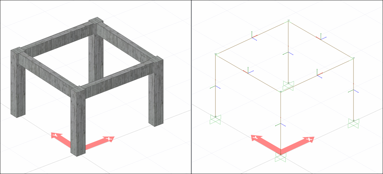
Column and beam elements are modeled with beam finite elements, considering all 6 degrees of freedom at the nodal points. Shearwalls are modeled with shell finite elements (shell) containing degrees of freedom for both in-plane and out-of-plane displacements . At the nodes of shell finite elements, all 6 degrees of freedom are taken into account. Since the in-plane stresses of the slabs are assumed to be zero in the rigid diaphragm analysis model, the slabs are not modeled as a shell finite element.
The rigid diaphragm model is assumed to be quite large compared to the rigidity of the vertical structural system elements designed to meet the earthquake effects, and an analysis model is created. The difference between the center of mass and the center of stiffness causes torsion in the plane. Analysis with rigid diaphragm is based on the assumption that there is little or no in-plane deformation in slabs under the influence of earthquake. Since this deformation is not present, the slab in-plane stresses are not included in the analysis model.
Beam Finite Elements
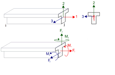
The internal forces of the beam finite elements (columns and beams) as a result of the analysis are shown according to the local beam axis (local axis) direction assumption. A bar element with 3D analysis has 3 local axes. These local axes may vary according to the position and placement of the bar. An exemplary view of local axes in rod elements is shown in the figure below.
The relationship between the numbers and colors of the local axes in the beam elements is as follows.
1 direction - Red
2 direction - Green
3 direction - Blue
There are 6 degrees of freedom in a cross-section of a bar element for which three-dimensional analysis is performed. These are translations in directions 1,2 and 3 and rotations about 1,2 and 3.
For detailed information; Element Local Axes
Shell Finite Elements
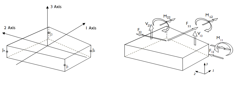
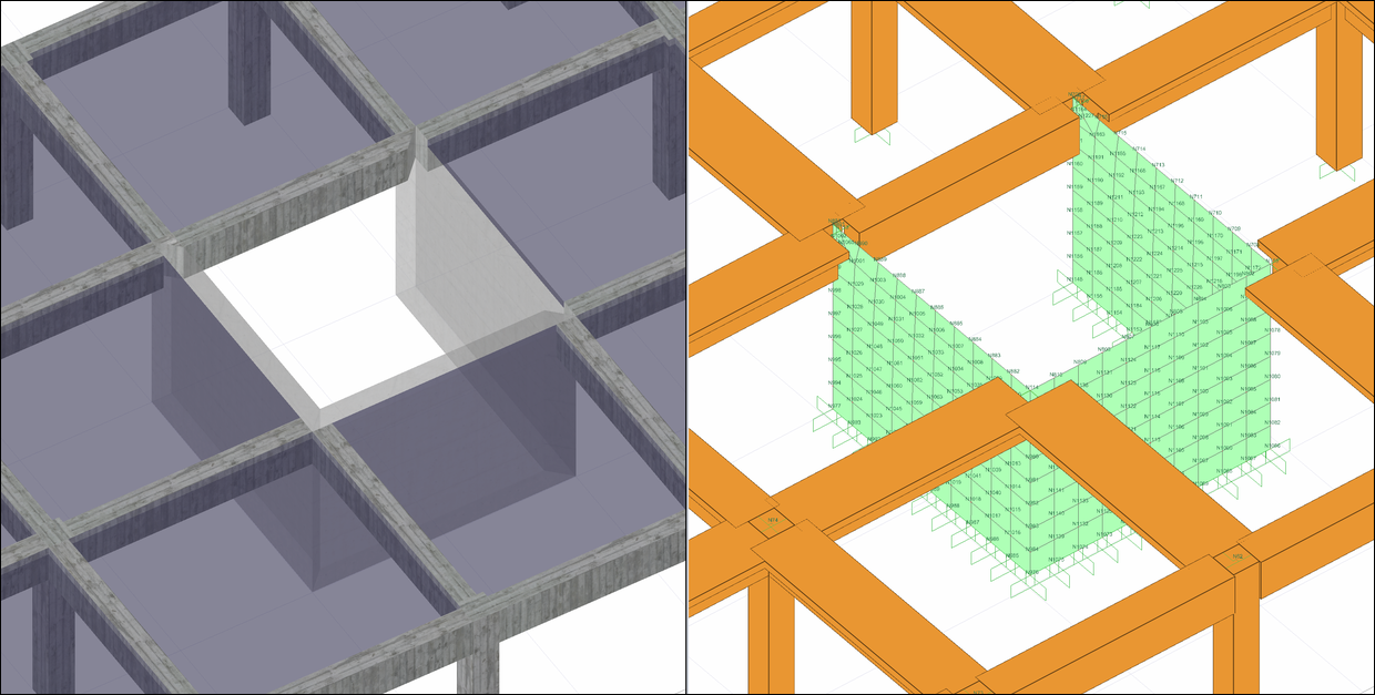
In the rigid diaphragm analysis model, shell finite elements are used for the bulkheads. As a result of three-dimensional analysis of shell finite elements (slabs, shearwalls and polygon shearwalls) used for shearwalls, stresses and forces per unit length form. The directions of these stresses and forces per unit length are determined according to the local axes of the shell finite element.
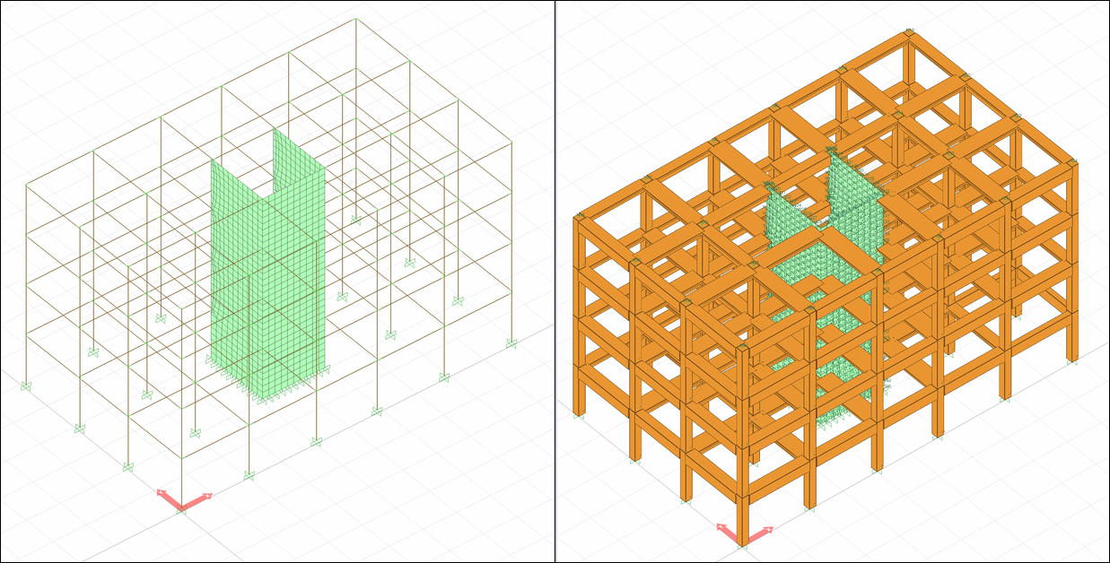
Shell finite element forces are obtained as a result of stresses formed by shell finite elements in three-dimensional analysis.
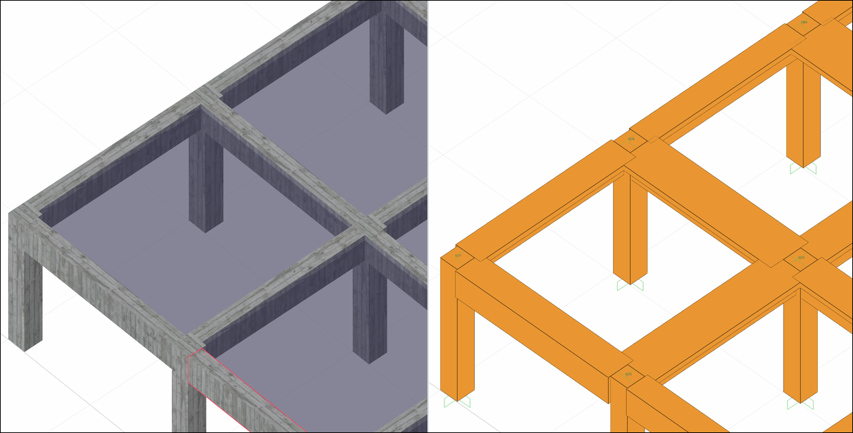
The analysis results of a structure with slabs and shearwalls modeled with shell finite elements can be seen as follows.
For detailed information; Local Axes of Shell Elements
Beam and Shell Finite Element Connections
In the analysis model established for the rigid diaphragm solution, the columns are included in the analysis system with the rigidities of the dimensions they are defined. When the analysis model of the beams connected with the slabs is established, the section with the table is accepted. In the analysis model shown as a solid-body system in the picture below, it can be observed that the beams are included in the analysis model by calculating the appropriate table dimensions.
The analysis model is created automatically by connecting the curtains and beams with the appropriate link elements.
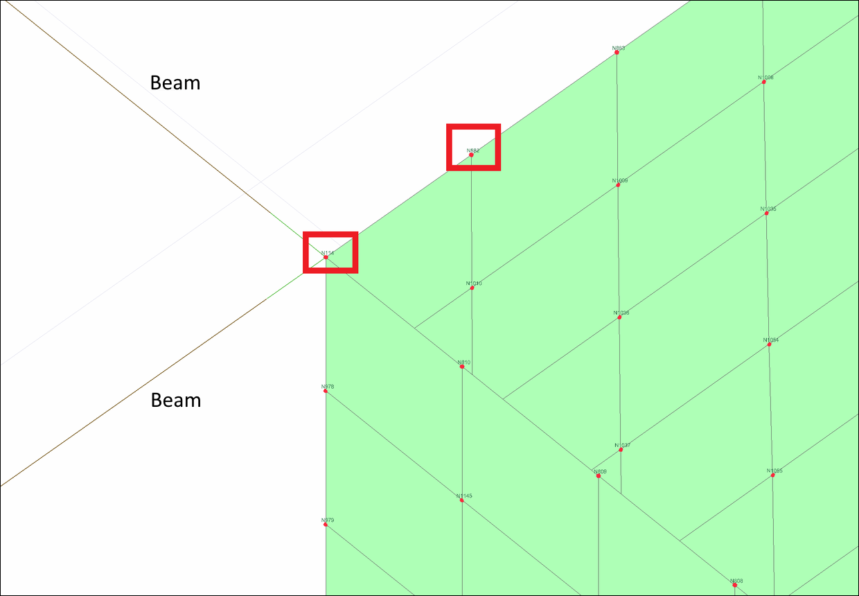
While constructing the analysis model of the shear beam connection, the bar finite element representing the beam element and the acceptance finite element representing the shearwalls are connected to more than one node to represent the actual behavior between the beam and the shearwall. In the picture below, the joint points connected by the link element in the analysis model of the beam-shearwall connection are shown by marking them in red.
Green Link Elements
It connects concrete columns and beams along their long axis. The length of the link element is automatically defined in accordance with the column-beam layout, taking into account the column dimensions and misalignment in the column-beam junction area.
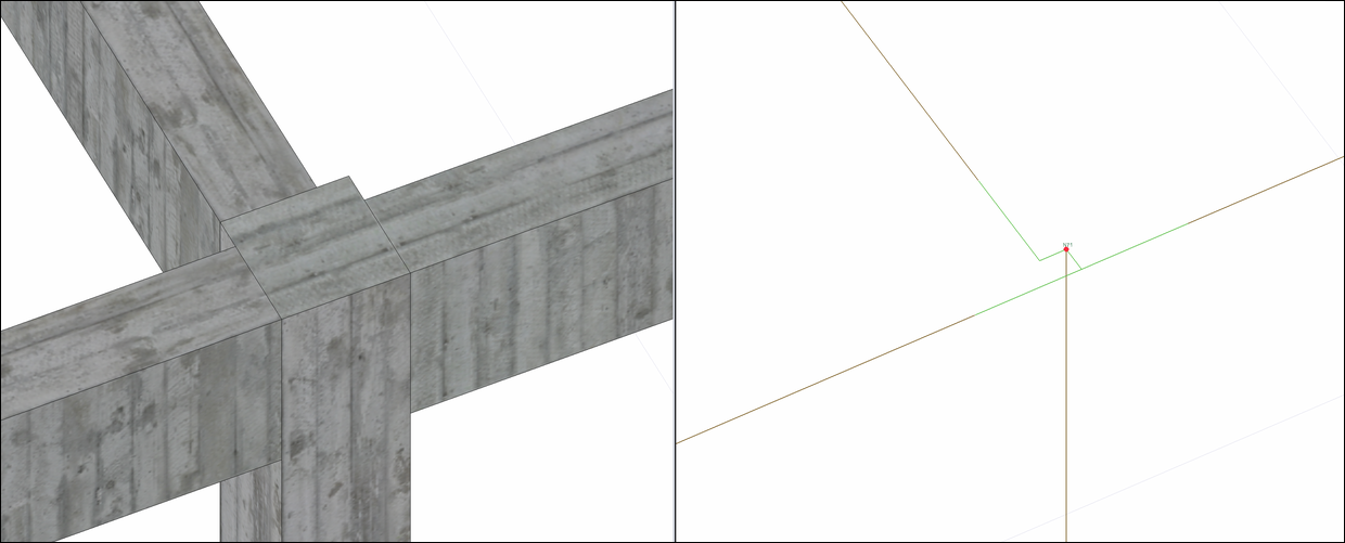
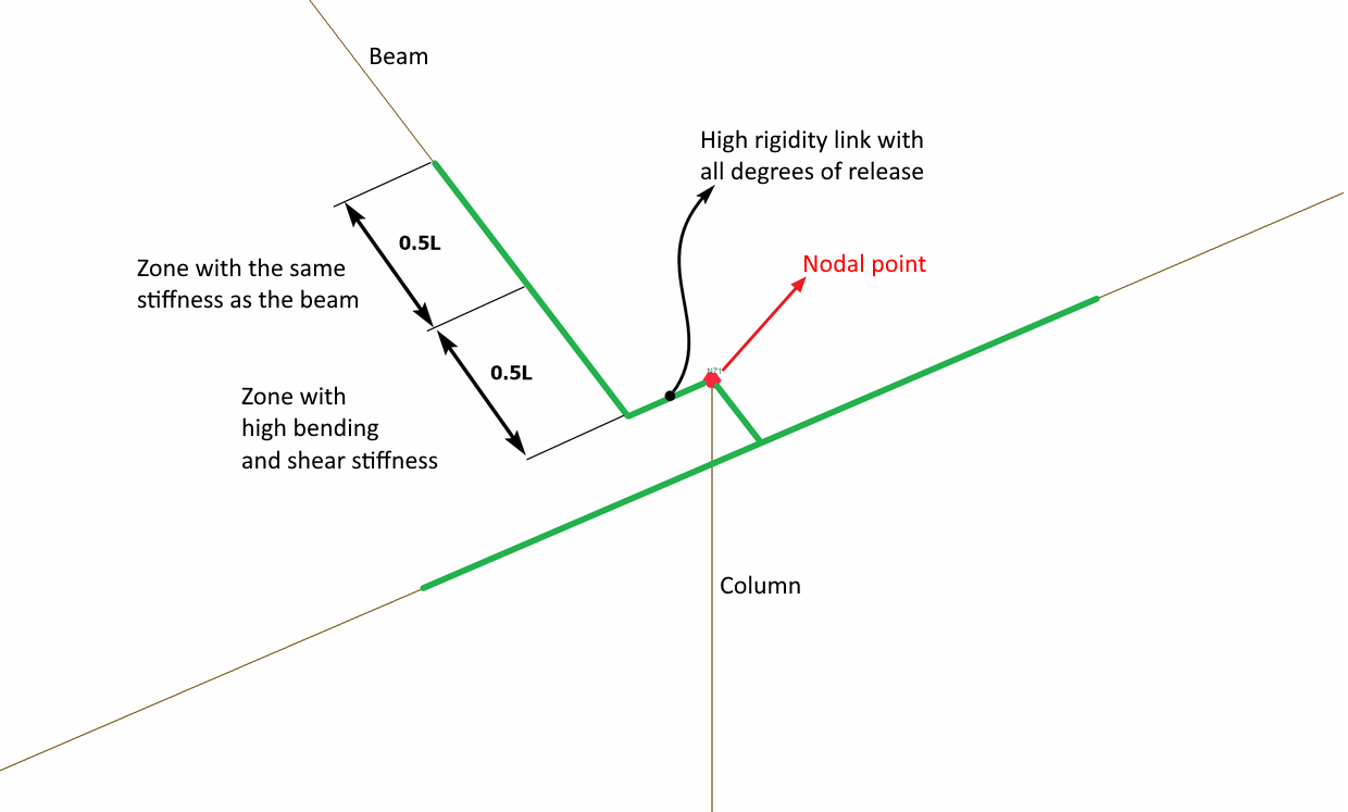
In the green link element defined on the concrete beam axis, half of the link length in the continuation of the beam has the same stiffness values as the beam, and the remaining half of the length has very high bending and shear stiffness. In the section with high stiffness, the moment in the 3 direction and the shear stiffness in the 2 direction have high values relative to the local axis of the beam. In case of misalignment, stiffnesses in all directions are defined as high (infinite) value. The picture below illustrates this situation. The length L is defined as the length of the link element.
Next Topic