
Project inner dimensions are given with the inner dimension command. The dimensions of the structural elements such as walls and beams on the drawn line are given automatically. Internal dimension is from smart commands. After the dimensions are given, the changes made in the elements where the dimension passes are automatically reflected in the dimensions.
Location of the Inner Dimension Command
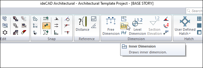
In the Architectural Program
You can access it under the ribbon menu Drawings tab, Dimension title.
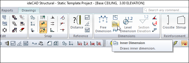
In the Structural Program
You can access under the ribbon menu Drawings tab, Dimension heading.
Dimension Toolbar
|
Icons |
|---|
|
Outer dimension Outer dimension command runs. |
|
Inner dimension Inner dimension command runs. |
|
Free dimension Free dimension command runs. |
|
Intersection dimension Intersection dimension command runs. |
|
Label Runs the label command. The dimension label is drawn. |
|
Level dimension Draws level dimension in the plan window. |
|
Section elevation It is used for section elevation in section and view windows. Only active in 2D drawing windows. |
|
Angle dimension Dimensions the angle between two objects. |
|
Radius dimension Dimensions entities drawn with a circle or arc and arc or circle axis in diameter or radius. |
|
Section dimension group Creates a section dimension group. It is active in section and view windows. |
|
Section dimension Creates a section dimension. It is active in section and view windows. |
|
Include beams Include beams in dimension. |
|
Include slabs Include slabs in section dimension. |
|
Include details Include door/window elements in section dimension. |
|
Left side Places the section dimension on the left. |
|
Right side Places the section dimension on the right. |
|
Settings When clicked, which dimension type is active (inner, outer, intersection etc.) opens the dimension settings dialog where the parameters related to that dimension are found. |
Usage Steps
To create an inner dimension:
-
Click the Inner Dimension icon in the ribbon menu .
-
Select a dimension line that cuts the walls by clicking two points with the left mouse button.
-
Inner dimension will occur on the line you have specified.
Inner dimension can be at any angle in the drawing area. Dimensions are automatically updated if the dimension line is moved or rotated, or if there is any change in the walls.
|
Usage step |
|---|
|
Giving the first point for the dimension line 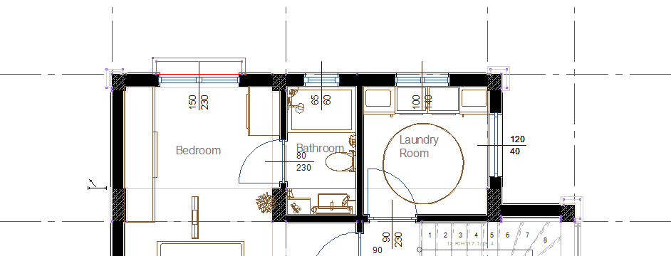
|
|
Giving the second point for the dimension line 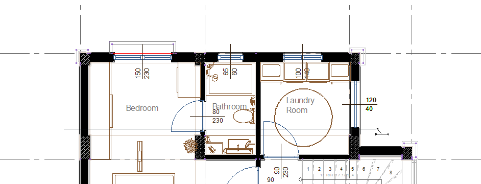
|
|
Creation of inner dimension 
|
Location of the Inner Dimension Settings Dialog
Inner Dimension Command Settings
You can access it under Free Dimension in the Drawings tab of the Ribbon menu .
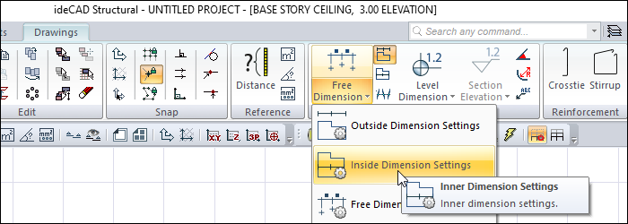
You can also access it by clicking the Settings icon in the dimension auxiliary toolbar that appears after the inner dimension command is run.
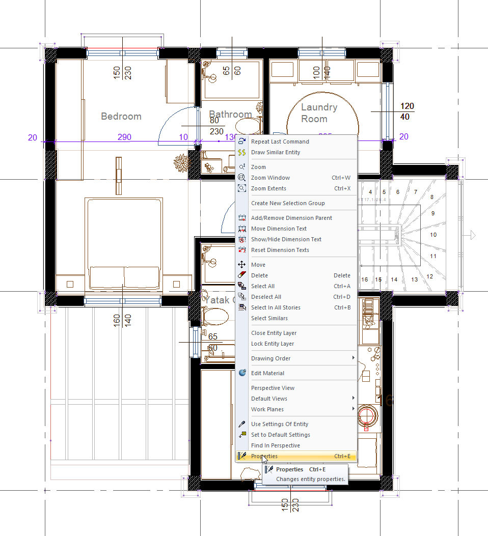
Inner Dimension Object Settings
Select the internal dimension you want to enter its settings and click the Properties line from the menu that opens by clicking the right button of the mouse.
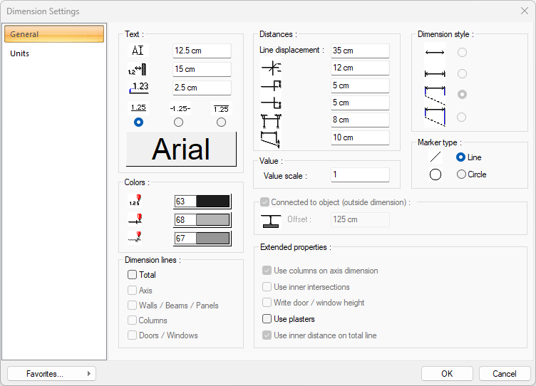
Dimension Settings - General Tab
Properties on the tab change as active or inactive according to the dimensioning type.
|
Specifications |
|---|
|
Text Section |
|
The font height of the dimensions is entered. |
|
The distance of the dimension text from the objects is entered. |
|
The distance of the dimension text to the dimension line is entered. |
|
The position of the dimension text relative to the dimension line is selected. |
|
When the button is clicked, the "Font Settings" dialog appears. Font of information text can be set here. |
|
Distances Section |
|
Line displacement The distance from the dimension lines to each other is determined. |
|
The size of the cross separators is entered in the dimension lines. |
|
Upper marker size of the dimension line is entered. |
|
The bottom marker size of the dimension line is entered. |
|
How long the dimension line will continue after the left and right end reference points is entered. |
|
The distance of the dimension line from the curved objects taken as reference by the bottom separator is entered. |
|
Colors Section |
|
Sets the color of the dimension text. When the color box is clicked, the appropriate color is selected from the window that opens. |
|
Sets the color of the dimension lines. When the color box is clicked, the appropriate color is selected from the window that opens. |
|
Sets the color of the markers. When the color box is clicked, the appropriate color is selected from the window that opens. |
|
Value scale The actual length values written on the dimension line are multiplied with the value written here and the value found at the result of multiplication is used as the measurement value. For example, the dimension line values are 120, 200, 350. If 2 is written to the scale value, the lengths of 120, 200, 250 will be written as 240, 400, 700 in the dimensioning line. |
|
Marker type 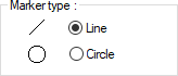
One of the two marker types that can be used in dimensioning is selected. |
|
Dimension lines - Total It gives the total length of all lines. |
|
Extended properties section |
|
Use plasters It shows the wall by taking the width from wall plaster to wall plaster in the inner dimension line. If not marked, the wall will measure the width of the wall. |
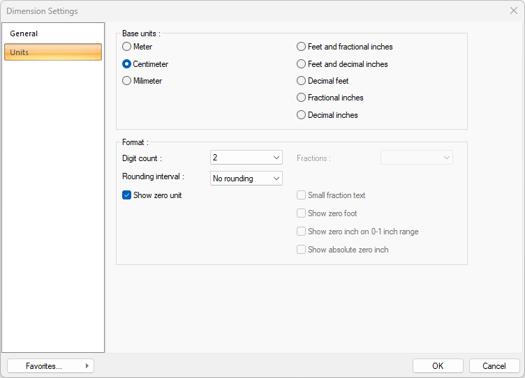
Dimension Settings - Units Tab
|
Specifications |
|---|
|
Basic units 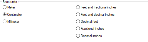
One of the selections is activated by clicking the left mouse button on the job. Meter : If checked, the unit of information text will be meters.
|
|
Digit count 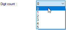
It determines how many digits will be shown after the comma. The desired number is selected from the list. For example, if 2 is selected, units will be shown as two digits after the comma. If 0 is selected, units will not be shown after the comma. |
|
Fractions 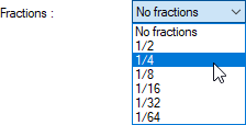
It determines the precision of the dimension to be made in fractional inch format. In the list, there are options with a sensitivity of 1/2, ¼, 1/8, 1/16, 1/32, 1/34. If "no fraction" is selected, units will appear without fractions. |
|
Rounding interval 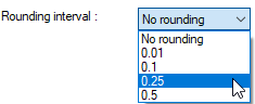
It determines the rounding range of the measurement to be made in meters, centimeters or millimeters. If No rounding is selected, the dimensioning is done at exact value. As the range gets larger, the dimensioning is rounded up to the selected range. |
|
Show zero unit If it is not checked, it does not show the zero and point on the left in dimensioning. For example, it measures 0.20 as 20. If marked, the value 0.20 is scaled as 0.20. |
|
Small fraction text When fractional inch format is selected, determines the fractional part to display in upper / lower case. If it is checked, the fraction is slightly above the integer and small, if not, the fraction is shown the same size next to the integer. |
|
Show zero foot Determines whether 0 is displayed in the 0-foot gauge (less than 1 foot gauge). For example, if it is not checked, it will show a measure of 0 '- 15 "as -15". If marked, it shows as 0'-15 ". |
|
Show zero inch on 0-1 inch range For example, a dimension inch with a value of 8'-0 1/6 "is in the range 0-1. If the option is not ticked, the value 8'-0 1/6" will be displayed as 8'-. In other words, inch values in the 0-1 range will not be displayed. |
|
Show absolute zero inch Determines whether to show zero inches in the dimension value where inches is absolute zero. For example, a dimension of exactly 10 'will be displayed as 10'-0 "if this option is selected. If not checked, it will be displayed as 10" -. |
Next Topic