
With the Steel Brace Settings command, settings such as section, drawing, brace type, placement are accessed.
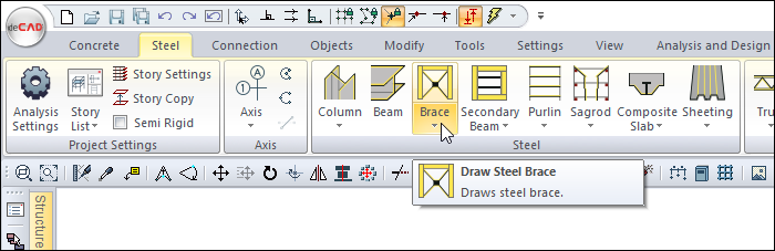
Location of Steel Brace Command
Click the setting icon in steel brace toolbar, which appears on the screen after the brace command runs.
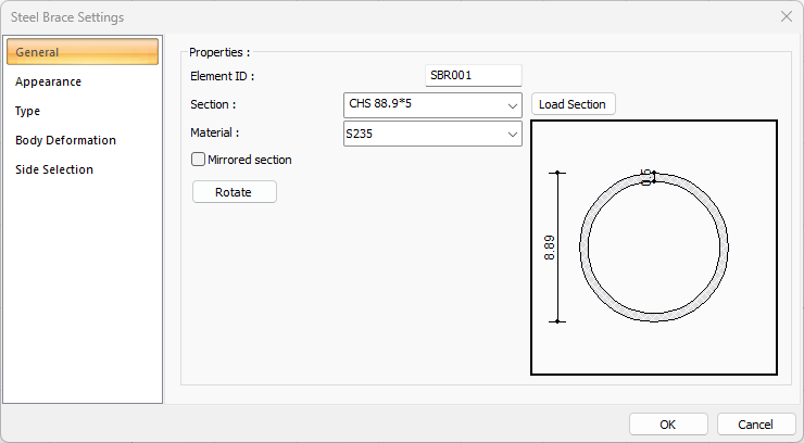
General Tab
|
Specifications |
|---|
|
Element ID It is the name of the steel cross that appears in the plan, reports and drawings. |
|
Section The profile used appears. One of the previously defined profiles can be selected by clicking the list, or a new profile can be selected from the dialog that opens when the Load Section button is clicked. |
|
Load section By accessing the ready section library, a list of American and European finished rolling sections is reached and a selection is made from the list. |
|
Material The material for the steel brace is selected. |
|
Mirrored section If the section is not symmetrical like a pipe profile, if the box is ticked, it places its cross arms symmetrically. |
|
Rotate Pressing each button 90 that is rotated in the direction of the section hour. |
|
Schematic drawing 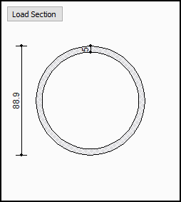
The schematic drawing and dimensions of the selected section are shown. |
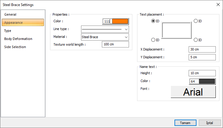
Appearance Tab
|
Specifications |
|---|
|
Color It is the color of the brace's border lines. It scrolls on the color palette that is opened by clicking and holding down the left mouse button. The button is released when the desired color is reached. The color box turns into the selected color. |
|
Line type Line type of the line forming the brace is selected in the plan. Clicking the down arrow buttons to the right of the boxes opens the list of line types. From this list, the desired line type is selected by clicking with the left mouse button. |
|
Material
The material to be covered on the solid model of the brace is selected. The brace is covered with the selected material and displayed in the solid model like this. |
|
Texture world length Texture length is entered. For example; If 1 meter is entered, the selected material texture is taken as 1 meter and covered on the selected object. Considering that the texture is in the form of a square, the object surfaces are covered with 1x1 textures arranged side by side. |
|
Text placement 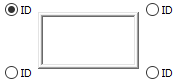
The position where the brace name will be written relative to the brace is determined according to the figure in the dialog. The program will place the name of the element according to the position selected when the column was created. |
|
X/Y Displacement X and Y coordinates are entered according to the upper right corner of the brace name. If the dimension X value is positive, the dimension text shifts to the left, if it is negative, it shifts to the right. If the dimension Y value is positive, the dimension text will scroll up, and if it is negative, it will scroll down. |
|
Name text 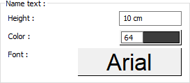
The height of the brace name text is entered. The color box is slid over the color palette that is opened by clicking and holding down the button with the left mouse button. The button is released when the desired color is reached. The color box turns into the selected color. If clicked together with the Shift key, the pen thickness of the relevant color can be adjusted. If the button below is clicked, the Font Settings dialog opens. Beam Name Text, font type is set from this dialog. |
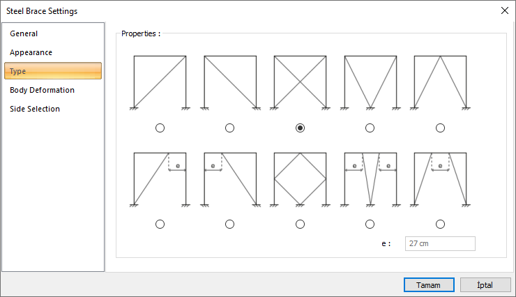
Type Tab
|
Specifications |
|---|
|
Concentrically braced system 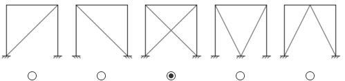
X, V, Inverse V etc. used to create a central braced system. Subtypes are selected. |
|
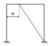
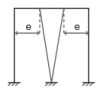
Eccentrically brace system 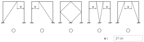
The subtypes used to create an eccentric brace system are selected and the offset is set with the e parameter. |
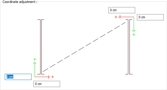
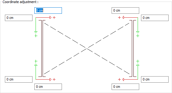
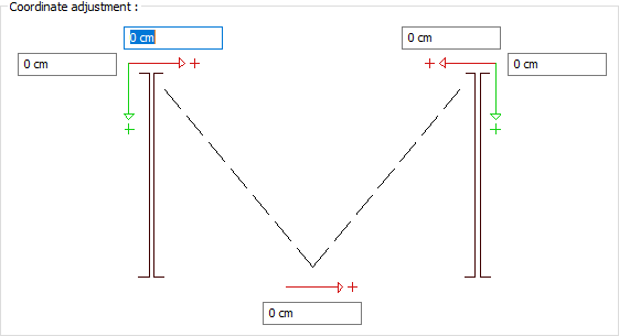
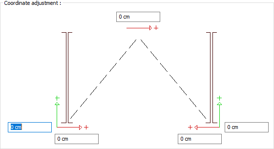
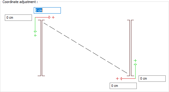
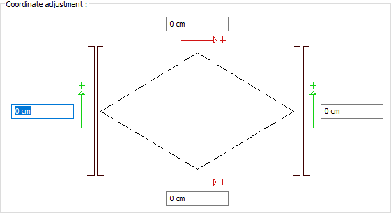
Body Deformation Tab
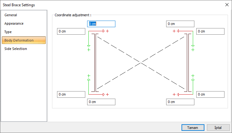
In order to prevent collisions at the start and end points of the elements defined with the coordinate adjustment settings section, offset arrangement is made in different planes.
|
Body deformation according to brace types |
|---|

|


|

|

|

|


|
|

|
|

|
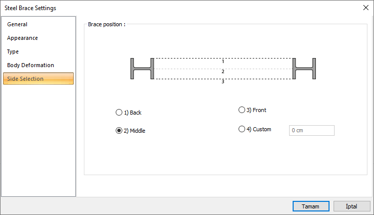
Side Selection Tab
|
Specifications |
|---|
|
Schematic drawing 
The directions are numbered and shown on the schematic drawing. |
|
1. Rear When viewed from the rear view of the elements it is defined, it provides a connection to the last end region. |
|
2. Medium It provides a connection from the midpoint of the elements it is defined. |
|
3. Front When viewed from the front view of the elements it is defined, it provides a connection to the first end region. |
|
4. Custom It provides connection of the custom elements from the distance entered in the box. |
Next Topic