
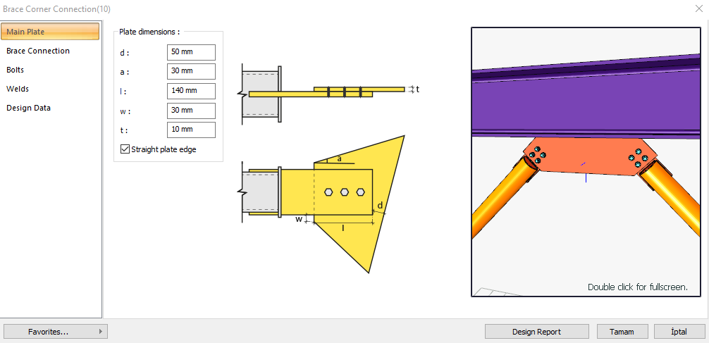
The brace corner connection is formed by bolting and welding the steel brace member to the column, beam or column-to-beam connection. Bolt control, weld control, plate control and connection application limits control are performed automatically according to the placement of the elements of the connection. Brace corner connection design is made automatically according to the Design, Calculation and Construction Principles of Steel Structures (ÇYTHYEDY) or AISC 360-16 regulations and a connection report is created.
In the brace corner connection calculation, horizontal and vertical bolt distances, end plate weld thickness, continuity plate weld thickness and application limits are checked under geometry control. In strength control, cross bolt slip, plate bolt hole crushing, ski control, Whitmore section buckling, plate pressure leakage are checked.
Connection Geometry
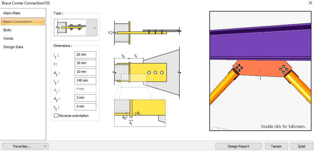
Brace - Gusset Plate Connection
Geometry Checks
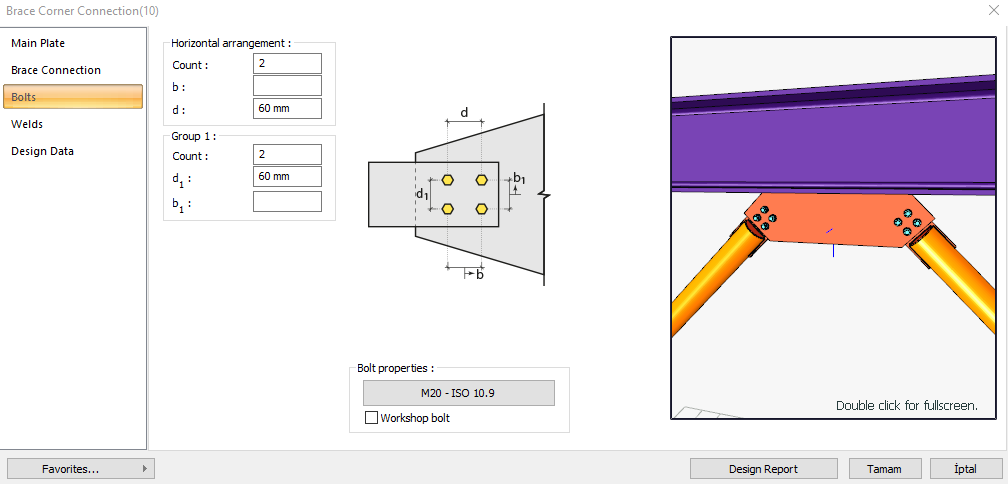
Bolt Spacing
|
s min ≥ 3d |
ÇYTHYEDY 13.3.6 |
|
|
|
s |
60 mm |
|
|
|
d |
20 mm |
s =60 mm > smin = 3*20=60 mm |
√ |
Horizontal Edge Distance
|
L eh ≥ L e- min |
ÇYTHYEDY 13.3.7 |
|
|
|
L eh |
33.5 mm |
|
√ |
|
L e- min |
26 mm |
Minimum distance check according to Table 13.9 |
√ |
Vertical Edge Distance
|
L ev ≥ L e- min |
ÇYTHYEDY 13.3.7 |
|
|
|
L ev |
40 mm |
Conformity check for L eh ≥ 2d = 2 * 20 = 40 mm application |
√ |
|
L e- min |
26 mm |
Minimum distance check according to Table 13.9 |
√ |
Weld Size
|
a ≥ a min |
ÇYTHYEDY 13.3.7 |
|
|
|
a |
4 mm |
|
√ |
|
a min |
3.5 mm |
Table 13.4 |
√ |
Strength Checks
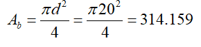
Bolt Shear at Brace
|
A b |
|
|
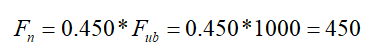
Fn |
|
|
Rn |
|
|
ΦRn |
|
|
Required |
Available |
Ratio |
Control |
|---|---|---|---|
|
367,989 kN |
424.115 kN |
0.868 |
√ |
Bolt Bearing on Plate
|
d h |
20+2=22 mm |
|
|
Lc,edge |
|
|
|
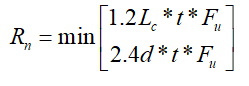
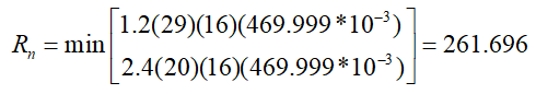
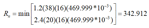
Rn |
|
ÇYTHYEDY 13.3.13 Equation 13.14a and13.14b |
|
Rn-edge |
|
|
|
Lc,spacing |
|
|
|
Rn-spacing |
|
|
|
Rn |

|
|
|
ΦRn |
|
|
|
Required |
Available |
Ratio |
Control |
|---|---|---|---|
|
367,989 kN |
906.912 kN |
0.406 |
√ |
Bolt Bearing on Gusset
|
d h |
20+2=22 mm |
|
|
Lc,edge |
|
|
|
Rn |
|
ÇYTHYEDY 13.3.13 Equation 13.14a and13.14b |
|
Rn-edge |
|
|
|
Lc,spacing |
|
|
|
Rn-spacing |
|
|
|
Rn |

|
|
|
ΦRn |
|
|
|
Required |
Available |
Ratio |
Control |
|---|---|---|---|
|
367,989 kN |
566.82 kN |
0.649 |
√ |
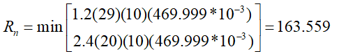
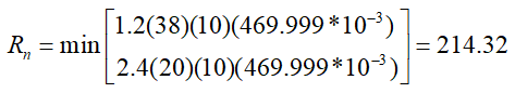
Weld Strength
|
Fe |
490000 kN/m2 |
|
w |
The weld thickness taken from the combination menu is 0.707 * w value. 4 / 0.707 = 5.658 mm |
|
F u-plate |
469.999 N/mm2 |
|
F u-brace |
410 N/mm2 |
|
tplate |
16 mm |
|
t brace |
10 mm |
|
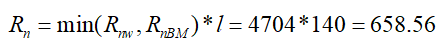
R nw |
|
|
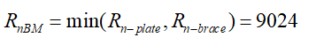
Rn-plate |
|
|
Rn-brace |
|
|
RnBM |
|
|
Rn |
|
|
ΦRn |
|
|
Required |
Available |
Ratio |
Control |
|---|---|---|---|
|
367,989 kN |
493.92 kN |
0.745 |
√ |
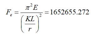
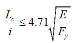
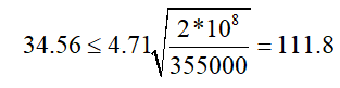
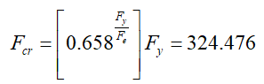
Whitmore Section Buckling
|
K |
0.65 |
|
|
L |
153.5 mm |
|
|
r |
2.887 mm |
|
|
KL / r |
34.56 |
|
|
Fy |
355 N/mm2 |
|
|
Ag |
1881.409 mm2 |
|
|
Fe |
|
|
|
|
|
|
|
|
|
|
|
Fcr |
|
|
|
Rn |
|
|
|
ΦRn |
|
|
|
Required |
Available |
Ratio |
Control |
|---|---|---|---|
|
367,989 kN |
549.42 kN |
0.670 |
√ |
Gusset Axial Yield
|
K |
0.65 |
|
|
L |
60 mm |
|
|
r |
4.619 mm |
|
|
KL / r |
8.44 |
|
|
Fy |
355 N/mm2 |
|
|
Ag |
2991.995 mm2 |
|
|
Rn |
|
ÇYTHYEDY 13.20 |
|
ΦRn |
|
|
|
Required |
Available |
Ratio |
Control |
|---|---|---|---|
|
367,989 kN |
955,942 kN |
0.385 |
√ |
Gusset to Beam Connection
Geometry Checks
Weld Size
|
a ≥ a min |
ÇYTHYEDY 13.3.7 |
|
|
|
a |
4 mm |
|
√ |
|
a min |
3.5 mm |
Table 13.4 |
√ |
Strength Checks
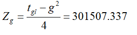
Gusset Axial Yield
|
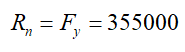
F y |
355 N/mm2 |
|
|
Z |
|
|
|
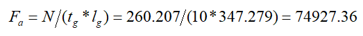
F a |
|
|
|
N |
260,207 kN |
|
|
M |
10.775 kNm |
|
|
tg |
10 mm |
|
|
l g |
347.279 mm |
|
|
F b |
|
|
|
Fn |
|
|
|
Rn |
|
|
|
ΦRn |
|
|
|
Required |
Available |
Ratio |
Control |
|---|---|---|---|
|
110666.08 kN/m2 |
319500 kN/m2 |
0.346 |
√ |
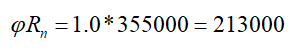
Gusset Shear Yield
|
F y |
355 N/mm2 |
|
|
V |
260,207 kN |
|
|
tg |
10 mm |
|
|
l g |
347.279 mm |
|
|
Fv |
|
|
|
Rn |
|
|
|
ΦRn |
|
|
|
Required |
Available |
Ratio |
Control |
|---|---|---|---|
|
74927.3 kN/m2 |
213000 kN/m2 |
0.352 |
√ |
Weld Strength
|
Fpeak |

|
|
|
Favg |

|
|
|
R req |
|
ÇYTHYEDY 13.3 |
|
tg |
10 mm |
|
|
in |
5.658 mm |
|
|
F e |
480000 kN/m2 |
|
|
θ |
55.9 ° |
|
|
Rn |
|
|
|
ΦRn |
|
|
|
Required |
Available |
Ratio |
Control |
|---|---|---|---|
|
1363.764 kN/m |
2428.6 kN/m |
0.562 |
√ |
Next Topic
Related Topics