
How does ideCAD calculate the column's shear strength according to ACI 318-19?
-
Column shear design and required strengths are calculated automatically.
Notation
Av = area of shear reinforcement within spacing s, in.2
Av,min = minimum area of shear reinforcement within spacing s, in.2
bw = width of compression face of member, in.
c1 = dimension of rectangular or equivalent rectangular column, capital, or bracket measured in the direction of the span for which moments are being determined, in.
d = distance from extreme compression fiber to centroid of longitudinal tension reinforcement, in.
D = dead load
E = earthquake load
fc' = specified compressive strength of concrete, psi
fy = specified yield strength for nonprestressed reinforcement, psi
fyt = specified yield strength of transverse reinforcement, psi
ln = length of clear span measured face-to-face of supports, in.
lu = unsupported length of column or wall, in.
L = live load
Lr = roof live load
Mn = nominal flexural strength at section, in.-lb
Mpr = probable flexural strength of members, with or without axial load, determined using the properties of the member at joint faces assuming a tensile stress in the longitudinal bars of at leasts 1.25fy and a strength reduction factor ϕ of 1.0, in.-lb
Pn = nominal axial compressive strength of member, lb
Pu = factored axial force; to be taken as positive for compression and negative for tension, lb
R = rain load
S = snow load
s = center-to-center spacing of items, such as longitudinal reinforcement, transverse reinforcement, tendons, or anchors, in.
Tn = nominal torsional moment strength, in.-lb
Tu = factored torsional moment at section, in.-lb
Vc = nominal shear strength provided by concrete, lb
Ve = design shear force for load combinations including earthquake effects, lb
Veb = Capacity shear force of the column based on the maximum probable moment strengths of the beams framing into the column, lb
Vec = Capacity shear force of the column based on the maximum probable flexural strengths of the two ends of the column, lb
Vn = nominal shear strength, lb
Vs = nominal shear strength provided by shear reinforcement, lb
Vu = factored shear force at section, lb
W = wind load
ϕ = strength reduction factor
Ωo = overstrength factor for the lateral-force-resisting system given in ASCE Table 12.2-1.
Download ideCAD for ACI 318-19
Required strength
The required strength is calculated in accordance with the factored load combinations in Load Factors and Combinations per ACI 318-19 with ideCAD title. The required shear strength of a column Vu , is obtained from Load Combinations given in ACI Table 5.3.1.
'%3e%3cg transform='translate(167%2c0)'%3e%3cg transform='translate(-13%2c0)'%3e%3cg transform='translate(0%2c3501)'%3e%3cuse xlink:href='%23MJMATHI-55' x='0' y='0'%3e%3c/use%3e%3cuse xlink:href='%23MJMAIN-3D' x='1045' y='0'%3e%3c/use%3e%3cg transform='translate(2101%2c0)'%3e%3cuse xlink:href='%23MJMAIN-31'%3e%3c/use%3e%3cuse xlink:href='%23MJMAIN-2E' x='500' y='0'%3e%3c/use%3e%3cuse xlink:href='%23MJMAIN-34' x='779' y='0'%3e%3c/use%3e%3c/g%3e%3cuse xlink:href='%23MJMATHI-44' x='3381' y='0'%3e%3c/use%3e%3c/g%3e%3cg transform='translate(0%2c2101)'%3e%3cuse xlink:href='%23MJMATHI-55' x='0' y='0'%3e%3c/use%3e%3cuse xlink:href='%23MJMAIN-3D' x='1045' y='0'%3e%3c/use%3e%3cg transform='translate(2101%2c0)'%3e%3cuse xlink:href='%23MJMAIN-31'%3e%3c/use%3e%3cuse xlink:href='%23MJMAIN-2E' x='500' y='0'%3e%3c/use%3e%3cuse xlink:href='%23MJMAIN-32' x='779' y='0'%3e%3c/use%3e%3c/g%3e%3cuse xlink:href='%23MJMATHI-44' x='3381' y='0'%3e%3c/use%3e%3cuse xlink:href='%23MJMAIN-2B' x='4431' y='0'%3e%3c/use%3e%3cg transform='translate(5432%2c0)'%3e%3cuse xlink:href='%23MJMAIN-31'%3e%3c/use%3e%3cuse xlink:href='%23MJMAIN-2E' x='500' y='0'%3e%3c/use%3e%3cuse xlink:href='%23MJMAIN-36' x='779' y='0'%3e%3c/use%3e%3c/g%3e%3cuse xlink:href='%23MJMATHI-4C' x='6712' y='0'%3e%3c/use%3e%3cuse xlink:href='%23MJMAIN-2B' x='7615' y='0'%3e%3c/use%3e%3cg transform='translate(8616%2c0)'%3e%3cuse xlink:href='%23MJMAIN-30'%3e%3c/use%3e%3cuse xlink:href='%23MJMAIN-2E' x='500' y='0'%3e%3c/use%3e%3cuse xlink:href='%23MJMAIN-35' x='779' y='0'%3e%3c/use%3e%3c/g%3e%3cuse xlink:href='%23MJMAIN-28' x='9895' y='0'%3e%3c/use%3e%3cg transform='translate(10285%2c0)'%3e%3cuse xlink:href='%23MJMATHI-4C' x='0' y='0'%3e%3c/use%3e%3cuse transform='scale(0.707)' xlink:href='%23MJMATHI-72' x='963' y='-213'%3e%3c/use%3e%3c/g%3e%3cuse xlink:href='%23MJMATHI-6F' x='11663' y='0'%3e%3c/use%3e%3cuse xlink:href='%23MJMATHI-72' x='12149' y='0'%3e%3c/use%3e%3cuse xlink:href='%23MJMATHI-53' x='12878' y='0'%3e%3c/use%3e%3cuse xlink:href='%23MJMATHI-6F' x='13802' y='0'%3e%3c/use%3e%3cuse xlink:href='%23MJMATHI-72' x='14287' y='0'%3e%3c/use%3e%3cuse xlink:href='%23MJMATHI-52' x='15016' y='0'%3e%3c/use%3e%3cuse xlink:href='%23MJMAIN-29' x='15776' y='0'%3e%3c/use%3e%3c/g%3e%3cg transform='translate(0%2c650)'%3e%3cuse xlink:href='%23MJMATHI-55' x='0' y='0'%3e%3c/use%3e%3cuse xlink:href='%23MJMAIN-3D' x='1045' y='0'%3e%3c/use%3e%3cg transform='translate(2101%2c0)'%3e%3cuse xlink:href='%23MJMAIN-31'%3e%3c/use%3e%3cuse xlink:href='%23MJMAIN-2E' x='500' y='0'%3e%3c/use%3e%3cuse xlink:href='%23MJMAIN-32' x='779' y='0'%3e%3c/use%3e%3c/g%3e%3cuse xlink:href='%23MJMATHI-44' x='3381' y='0'%3e%3c/use%3e%3cuse xlink:href='%23MJMAIN-2B' x='4431' y='0'%3e%3c/use%3e%3cg transform='translate(5432%2c0)'%3e%3cuse xlink:href='%23MJMAIN-31'%3e%3c/use%3e%3cuse xlink:href='%23MJMAIN-2E' x='500' y='0'%3e%3c/use%3e%3cuse xlink:href='%23MJMAIN-36' x='779' y='0'%3e%3c/use%3e%3c/g%3e%3cuse xlink:href='%23MJMAIN-28' x='6712' y='0'%3e%3c/use%3e%3cg transform='translate(7101%2c0)'%3e%3cuse xlink:href='%23MJMATHI-4C' x='0' y='0'%3e%3c/use%3e%3cuse transform='scale(0.707)' xlink:href='%23MJMATHI-72' x='963' y='-213'%3e%3c/use%3e%3c/g%3e%3cuse xlink:href='%23MJMATHI-6F' x='8480' y='0'%3e%3c/use%3e%3cuse xlink:href='%23MJMATHI-72' x='8965' y='0'%3e%3c/use%3e%3cuse xlink:href='%23MJMATHI-53' x='9694' y='0'%3e%3c/use%3e%3cuse xlink:href='%23MJMATHI-6F' x='10618' y='0'%3e%3c/use%3e%3cuse xlink:href='%23MJMATHI-72' x='11103' y='0'%3e%3c/use%3e%3cuse xlink:href='%23MJMATHI-52' x='11832' y='0'%3e%3c/use%3e%3cuse xlink:href='%23MJMAIN-29' x='12592' y='0'%3e%3c/use%3e%3cuse xlink:href='%23MJMAIN-2B' x='13204' y='0'%3e%3c/use%3e%3cuse xlink:href='%23MJMAIN-28' x='14204' y='0'%3e%3c/use%3e%3cg transform='translate(14594%2c0)'%3e%3cuse xlink:href='%23MJMAIN-31'%3e%3c/use%3e%3cuse xlink:href='%23MJMAIN-2E' x='500' y='0'%3e%3c/use%3e%3cuse xlink:href='%23MJMAIN-30' x='779' y='0'%3e%3c/use%3e%3c/g%3e%3cuse xlink:href='%23MJMATHI-4C' x='15873' y='0'%3e%3c/use%3e%3cuse xlink:href='%23MJMATHI-6F' x='16833' y='0'%3e%3c/use%3e%3cuse xlink:href='%23MJMATHI-72' x='17318' y='0'%3e%3c/use%3e%3cg transform='translate(18047%2c0)'%3e%3cuse xlink:href='%23MJMAIN-30'%3e%3c/use%3e%3cuse xlink:href='%23MJMAIN-2E' x='500' y='0'%3e%3c/use%3e%3cuse xlink:href='%23MJMAIN-35' x='779' y='0'%3e%3c/use%3e%3c/g%3e%3cuse xlink:href='%23MJMATHI-57' x='19327' y='0'%3e%3c/use%3e%3cuse xlink:href='%23MJMAIN-29' x='20375' y='0'%3e%3c/use%3e%3c/g%3e%3cg transform='translate(0%2c-801)'%3e%3cuse xlink:href='%23MJMATHI-55' x='0' y='0'%3e%3c/use%3e%3cuse xlink:href='%23MJMAIN-3D' x='1045' y='0'%3e%3c/use%3e%3cg transform='translate(2101%2c0)'%3e%3cuse xlink:href='%23MJMAIN-31'%3e%3c/use%3e%3cuse xlink:href='%23MJMAIN-2E' x='500' y='0'%3e%3c/use%3e%3cuse xlink:href='%23MJMAIN-32' x='779' y='0'%3e%3c/use%3e%3c/g%3e%3cuse xlink:href='%23MJMATHI-44' x='3381' y='0'%3e%3c/use%3e%3cuse xlink:href='%23MJMAIN-2B' x='4431' y='0'%3e%3c/use%3e%3cg transform='translate(5432%2c0)'%3e%3cuse xlink:href='%23MJMAIN-31'%3e%3c/use%3e%3cuse xlink:href='%23MJMAIN-2E' x='500' y='0'%3e%3c/use%3e%3cuse xlink:href='%23MJMAIN-30' x='779' y='0'%3e%3c/use%3e%3c/g%3e%3cuse xlink:href='%23MJMATHI-45' x='6712' y='0'%3e%3c/use%3e%3cuse xlink:href='%23MJMAIN-2B' x='7698' y='0'%3e%3c/use%3e%3cg transform='translate(8699%2c0)'%3e%3cuse xlink:href='%23MJMAIN-31'%3e%3c/use%3e%3cuse xlink:href='%23MJMAIN-2E' x='500' y='0'%3e%3c/use%3e%3cuse xlink:href='%23MJMAIN-30' x='779' y='0'%3e%3c/use%3e%3c/g%3e%3cuse xlink:href='%23MJMATHI-4C' x='9978' y='0'%3e%3c/use%3e%3cuse xlink:href='%23MJMAIN-2B' x='10882' y='0'%3e%3c/use%3e%3cg transform='translate(11883%2c0)'%3e%3cuse xlink:href='%23MJMAIN-30'%3e%3c/use%3e%3cuse xlink:href='%23MJMAIN-2E' x='500' y='0'%3e%3c/use%3e%3cuse xlink:href='%23MJMAIN-32' x='779' y='0'%3e%3c/use%3e%3c/g%3e%3cuse xlink:href='%23MJMATHI-53' x='13162' y='0'%3e%3c/use%3e%3c/g%3e%3cg transform='translate(0%2c-2201)'%3e%3cuse xlink:href='%23MJMATHI-55' x='0' y='0'%3e%3c/use%3e%3cuse xlink:href='%23MJMAIN-3D' x='1045' y='0'%3e%3c/use%3e%3cg transform='translate(2101%2c0)'%3e%3cuse xlink:href='%23MJMAIN-30'%3e%3c/use%3e%3cuse xlink:href='%23MJMAIN-2E' x='500' y='0'%3e%3c/use%3e%3cuse xlink:href='%23MJMAIN-39' x='779' y='0'%3e%3c/use%3e%3c/g%3e%3cuse xlink:href='%23MJMATHI-44' x='3381' y='0'%3e%3c/use%3e%3cuse xlink:href='%23MJMAIN-2B' x='4431' y='0'%3e%3c/use%3e%3cg transform='translate(5432%2c0)'%3e%3cuse xlink:href='%23MJMAIN-31'%3e%3c/use%3e%3cuse xlink:href='%23MJMAIN-2E' x='500' y='0'%3e%3c/use%3e%3cuse xlink:href='%23MJMAIN-30' x='779' y='0'%3e%3c/use%3e%3c/g%3e%3cuse xlink:href='%23MJMATHI-57' x='6712' y='0'%3e%3c/use%3e%3c/g%3e%3cg transform='translate(0%2c-3601)'%3e%3cuse xlink:href='%23MJMATHI-55' x='0' y='0'%3e%3c/use%3e%3cuse xlink:href='%23MJMAIN-3D' x='1045' y='0'%3e%3c/use%3e%3cg transform='translate(2101%2c0)'%3e%3cuse xlink:href='%23MJMAIN-30'%3e%3c/use%3e%3cuse xlink:href='%23MJMAIN-2E' x='500' y='0'%3e%3c/use%3e%3cuse xlink:href='%23MJMAIN-39' x='779' y='0'%3e%3c/use%3e%3c/g%3e%3cuse xlink:href='%23MJMATHI-44' x='3381' y='0'%3e%3c/use%3e%3cuse xlink:href='%23MJMAIN-2B' x='4431' y='0'%3e%3c/use%3e%3cg transform='translate(5432%2c0)'%3e%3cuse xlink:href='%23MJMAIN-31'%3e%3c/use%3e%3cuse xlink:href='%23MJMAIN-2E' x='500' y='0'%3e%3c/use%3e%3cuse xlink:href='%23MJMAIN-30' x='779' y='0'%3e%3c/use%3e%3c/g%3e%3cuse xlink:href='%23MJMATHI-45' x='6712' y='0'%3e%3c/use%3e%3c/g%3e%3c/g%3e%3c/g%3e%3c/g%3e%3c/svg%3e)
Design strength
Design strength in all sections should satisfy all conditions given below;
-
ϕPn ≥ Pu
-
ϕMn ≥ Mu
-
ϕVn ≥ Vu
-
ϕTn ≥ Tu
Strength reduction factors ϕ is determined according to using ACI Table 21.2.1. Interaction between load effects is considered.
Nominal one-way shear strength at a column, Vn, is calculated by:
'%3e%3cg transform='translate(167%2c0)'%3e%3cg transform='translate(-13%2c0)'%3e%3cg transform='translate(0%2c-25)'%3e%3cuse xlink:href='%23MJMATHI-56' x='0' y='0'%3e%3c/use%3e%3cuse transform='scale(0.707)' xlink:href='%23MJMATHI-6E' x='825' y='-213'%3e%3c/use%3e%3cuse xlink:href='%23MJMAIN-3D' x='1385' y='0'%3e%3c/use%3e%3cg transform='translate(2442%2c0)'%3e%3cuse xlink:href='%23MJMATHI-56' x='0' y='0'%3e%3c/use%3e%3cuse transform='scale(0.707)' xlink:href='%23MJMATHI-63' x='825' y='-213'%3e%3c/use%3e%3c/g%3e%3cuse xlink:href='%23MJMAIN-2B' x='3654' y='0'%3e%3c/use%3e%3cg transform='translate(4655%2c0)'%3e%3cuse xlink:href='%23MJMATHI-56' x='0' y='0'%3e%3c/use%3e%3cuse transform='scale(0.707)' xlink:href='%23MJMATHI-73' x='825' y='-213'%3e%3c/use%3e%3c/g%3e%3cuse xlink:href='%23MJMAIN-28' x='11781' y='0'%3e%3c/use%3e%3cg transform='translate(12171%2c0)'%3e%3cuse xlink:href='%23MJMAIN-32'%3e%3c/use%3e%3cuse xlink:href='%23MJMAIN-32' x='500' y='0'%3e%3c/use%3e%3cuse xlink:href='%23MJMAIN-2E' x='1001' y='0'%3e%3c/use%3e%3cuse xlink:href='%23MJMAIN-35' x='1279' y='0'%3e%3c/use%3e%3cuse xlink:href='%23MJMAIN-2E' x='1780' y='0'%3e%3c/use%3e%3cuse xlink:href='%23MJMAIN-31' x='2058' y='0'%3e%3c/use%3e%3cuse xlink:href='%23MJMAIN-2E' x='2559' y='0'%3e%3c/use%3e%3cuse xlink:href='%23MJMAIN-31' x='2837' y='0'%3e%3c/use%3e%3c/g%3e%3cuse xlink:href='%23MJMAIN-29' x='15509' y='0'%3e%3c/use%3e%3c/g%3e%3c/g%3e%3c/g%3e%3c/g%3e%3c/svg%3e)
The nominal shear strength Vn is calculated as the sum of the nominal shear strength provided by concrete, Vc, and nominal shear strength provided by shear reinforcement Vs as shown in ACI Eq.(22.5.1.1).
The nominal shear strength Vn for a column is calculated in accordance with One-Way Shear Strength per ACI 318-19 with ideCAD title. In addition, Vs and Vc calculations are also described in the same title.
At each section of a column where Vu > ϕVc, transverse reinforcement is provided such that ACI Eq. (22.5.8.1) should be satisfied.
'%3e%3cg transform='translate(167%2c0)'%3e%3cg transform='translate(-13%2c0)'%3e%3cg transform='translate(0%2c20)'%3e%3cuse xlink:href='%23MJMATHI-56' x='0' y='0'%3e%3c/use%3e%3cuse transform='scale(0.707)' xlink:href='%23MJMATHI-73' x='825' y='-213'%3e%3c/use%3e%3cuse xlink:href='%23MJMAIN-2265' x='1293' y='0'%3e%3c/use%3e%3cg transform='translate(2071%2c0)'%3e%3cg transform='translate(397%2c0)'%3e%3crect stroke='none' width='889' height='60' x='0' y='220'%3e%3c/rect%3e%3cg transform='translate(60%2c537)'%3e%3cuse transform='scale(0.707)' xlink:href='%23MJMATHI-56' x='0' y='0'%3e%3c/use%3e%3cuse transform='scale(0.5)' xlink:href='%23MJMATHI-75' x='825' y='-213'%3e%3c/use%3e%3c/g%3e%3cuse transform='scale(0.707)' xlink:href='%23MJMATHI-3D5' x='330' y='-590'%3e%3c/use%3e%3c/g%3e%3c/g%3e%3cuse xlink:href='%23MJMAIN-2212' x='3701' y='0'%3e%3c/use%3e%3cg transform='translate(4702%2c0)'%3e%3cuse xlink:href='%23MJMATHI-56' x='0' y='0'%3e%3c/use%3e%3cuse transform='scale(0.707)' xlink:href='%23MJMATHI-63' x='825' y='-213'%3e%3c/use%3e%3c/g%3e%3cuse xlink:href='%23MJMAIN-28' x='11803' y='0'%3e%3c/use%3e%3cg transform='translate(12192%2c0)'%3e%3cuse xlink:href='%23MJMAIN-32'%3e%3c/use%3e%3cuse xlink:href='%23MJMAIN-32' x='500' y='0'%3e%3c/use%3e%3cuse xlink:href='%23MJMAIN-2E' x='1001' y='0'%3e%3c/use%3e%3cuse xlink:href='%23MJMAIN-35' x='1279' y='0'%3e%3c/use%3e%3cuse xlink:href='%23MJMAIN-2E' x='1780' y='0'%3e%3c/use%3e%3cuse xlink:href='%23MJMAIN-38' x='2058' y='0'%3e%3c/use%3e%3cuse xlink:href='%23MJMAIN-2E' x='2559' y='0'%3e%3c/use%3e%3cuse xlink:href='%23MJMAIN-31' x='2837' y='0'%3e%3c/use%3e%3c/g%3e%3cuse xlink:href='%23MJMAIN-29' x='15530' y='0'%3e%3c/use%3e%3c/g%3e%3c/g%3e%3c/g%3e%3c/g%3e%3c/svg%3e)
Vs is calculated using ACI Eq. (22.5.8.5.3) for a column reinforced with transverse reinforcement.
'%3e%3cg transform='translate(167%2c0)'%3e%3cg transform='translate(-13%2c0)'%3e%3cg transform='translate(0%2c-177)'%3e%3cuse xlink:href='%23MJMATHI-56' x='0' y='0'%3e%3c/use%3e%3cuse transform='scale(0.707)' xlink:href='%23MJMATHI-73' x='825' y='-213'%3e%3c/use%3e%3cuse xlink:href='%23MJMAIN-3D' x='1293' y='0'%3e%3c/use%3e%3cg transform='translate(2071%2c0)'%3e%3cg transform='translate(397%2c0)'%3e%3crect stroke='none' width='2181' height='60' x='0' y='220'%3e%3c/rect%3e%3cg transform='translate(60%2c698)'%3e%3cuse transform='scale(0.707)' xlink:href='%23MJMATHI-41' x='0' y='0'%3e%3c/use%3e%3cuse transform='scale(0.5)' xlink:href='%23MJMATHI-76' x='1061' y='-213'%3e%3c/use%3e%3cg transform='translate(844%2c0)'%3e%3cuse transform='scale(0.707)' xlink:href='%23MJMATHI-66' x='0' y='0'%3e%3c/use%3e%3cg transform='translate(346%2c-171)'%3e%3cuse transform='scale(0.5)' xlink:href='%23MJMATHI-79' x='0' y='0'%3e%3c/use%3e%3cuse transform='scale(0.5)' xlink:href='%23MJMATHI-74' x='497' y='0'%3e%3c/use%3e%3c/g%3e%3c/g%3e%3cuse transform='scale(0.707)' xlink:href='%23MJMATHI-64' x='2391' y='0'%3e%3c/use%3e%3c/g%3e%3cuse transform='scale(0.707)' xlink:href='%23MJMATHI-73' x='1307' y='-488'%3e%3c/use%3e%3c/g%3e%3c/g%3e%3cuse xlink:href='%23MJMAIN-28' x='10882' y='0'%3e%3c/use%3e%3cg transform='translate(11271%2c0)'%3e%3cuse xlink:href='%23MJMAIN-32'%3e%3c/use%3e%3cuse xlink:href='%23MJMAIN-32' x='500' y='0'%3e%3c/use%3e%3cuse xlink:href='%23MJMAIN-2E' x='1001' y='0'%3e%3c/use%3e%3cuse xlink:href='%23MJMAIN-35' x='1279' y='0'%3e%3c/use%3e%3cuse xlink:href='%23MJMAIN-2E' x='1780' y='0'%3e%3c/use%3e%3cuse xlink:href='%23MJMAIN-38' x='2058' y='0'%3e%3c/use%3e%3cuse xlink:href='%23MJMAIN-2E' x='2559' y='0'%3e%3c/use%3e%3cuse xlink:href='%23MJMAIN-35' x='2837' y='0'%3e%3c/use%3e%3cuse xlink:href='%23MJMAIN-2E' x='3338' y='0'%3e%3c/use%3e%3cuse xlink:href='%23MJMAIN-33' x='3616' y='0'%3e%3c/use%3e%3c/g%3e%3cuse xlink:href='%23MJMAIN-29' x='15388' y='0'%3e%3c/use%3e%3c/g%3e%3c/g%3e%3c/g%3e%3c/g%3e%3c/svg%3e)
Av is the effective area of all bar legs or wires within spacing s, for each rectangular tie, stirrup, hoop, or crosstie. For each circular tie or spiral, Av is two times the area of the bar or wire within spacing s.
Using equations ACI Eq. (22.5.8.1) and ACI Eq. (22.5.8.5.3), the required area of shear reinforcement, Av, and its spacing, s can be calculated as follows.
'%3e%3cg transform='translate(167%2c0)'%3e%3cg transform='translate(-13%2c0)'%3e%3cg transform='translate(0%2c32)'%3e%3cg transform='translate(120%2c0)'%3e%3crect stroke='none' width='964' height='60' x='0' y='220'%3e%3c/rect%3e%3cg transform='translate(60%2c537)'%3e%3cuse transform='scale(0.707)' xlink:href='%23MJMATHI-41' x='0' y='0'%3e%3c/use%3e%3cuse transform='scale(0.5)' xlink:href='%23MJMATHI-76' x='1061' y='-213'%3e%3c/use%3e%3c/g%3e%3cuse transform='scale(0.707)' xlink:href='%23MJMATHI-73' x='447' y='-488'%3e%3c/use%3e%3c/g%3e%3cuse xlink:href='%23MJMAIN-3D' x='1481' y='0'%3e%3c/use%3e%3cg transform='translate(2260%2c0)'%3e%3cg transform='translate(397%2c0)'%3e%3crect stroke='none' width='3112' height='60' x='0' y='220'%3e%3c/rect%3e%3cg transform='translate(60%2c602)'%3e%3cuse transform='scale(0.707)' xlink:href='%23MJMAIN-28' x='0' y='0'%3e%3c/use%3e%3cg transform='translate(275%2c0)'%3e%3cuse transform='scale(0.707)' xlink:href='%23MJMATHI-56' x='0' y='0'%3e%3c/use%3e%3cuse transform='scale(0.5)' xlink:href='%23MJMATHI-75' x='825' y='-213'%3e%3c/use%3e%3c/g%3e%3cuse transform='scale(0.707)' xlink:href='%23MJMAIN-2212' x='1477' y='0'%3e%3c/use%3e%3cuse transform='scale(0.707)' xlink:href='%23MJMATHI-3D5' x='2256' y='0'%3e%3c/use%3e%3cg transform='translate(2017%2c0)'%3e%3cuse transform='scale(0.707)' xlink:href='%23MJMATHI-56' x='0' y='0'%3e%3c/use%3e%3cuse transform='scale(0.5)' xlink:href='%23MJMATHI-63' x='825' y='-213'%3e%3c/use%3e%3c/g%3e%3cuse transform='scale(0.707)' xlink:href='%23MJMAIN-29' x='3842' y='0'%3e%3c/use%3e%3c/g%3e%3cg transform='translate(736%2c-425)'%3e%3cuse transform='scale(0.707)' xlink:href='%23MJMATHI-3D5' x='0' y='0'%3e%3c/use%3e%3cg transform='translate(421%2c0)'%3e%3cuse transform='scale(0.707)' xlink:href='%23MJMATHI-66' x='0' y='0'%3e%3c/use%3e%3cg transform='translate(346%2c-171)'%3e%3cuse transform='scale(0.5)' xlink:href='%23MJMATHI-79' x='0' y='0'%3e%3c/use%3e%3cuse transform='scale(0.5)' xlink:href='%23MJMATHI-74' x='497' y='0'%3e%3c/use%3e%3c/g%3e%3c/g%3e%3cuse transform='scale(0.707)' xlink:href='%23MJMATHI-64' x='1794' y='0'%3e%3c/use%3e%3c/g%3e%3c/g%3e%3c/g%3e%3cuse xlink:href='%23MJMAIN-28' x='12002' y='0'%3e%3c/use%3e%3cuse xlink:href='%23MJMATHI-52' x='12391' y='0'%3e%3c/use%3e%3cg transform='translate(13151%2c0)'%3e%3cuse xlink:href='%23MJMAIN-32'%3e%3c/use%3e%3cuse xlink:href='%23MJMAIN-32' x='500' y='0'%3e%3c/use%3e%3cuse xlink:href='%23MJMAIN-2E' x='1001' y='0'%3e%3c/use%3e%3cuse xlink:href='%23MJMAIN-35' x='1279' y='0'%3e%3c/use%3e%3cuse xlink:href='%23MJMAIN-2E' x='1780' y='0'%3e%3c/use%3e%3cuse xlink:href='%23MJMAIN-38' x='2058' y='0'%3e%3c/use%3e%3cuse xlink:href='%23MJMAIN-2E' x='2559' y='0'%3e%3c/use%3e%3cuse xlink:href='%23MJMAIN-35' x='2837' y='0'%3e%3c/use%3e%3c/g%3e%3cuse xlink:href='%23MJMAIN-29' x='16489' y='0'%3e%3c/use%3e%3c/g%3e%3c/g%3e%3c/g%3e%3c/g%3e%3c/svg%3e)
According to ACI 10.6.2; If shear reinforcement is required, Av,min is equal to the greater of the following relations;
'%3e%3cg transform='translate(167%2c0)'%3e%3cg transform='translate(-13%2c0)'%3e%3cg transform='translate(0%2c21)'%3e%3cuse xlink:href='%23MJMATHI-41' x='0' y='0'%3e%3c/use%3e%3cg transform='translate(750%2c-150)'%3e%3cuse transform='scale(0.707)' xlink:href='%23MJMATHI-76' x='0' y='0'%3e%3c/use%3e%3cuse transform='scale(0.707)' xlink:href='%23MJMAIN-2C' x='485' y='0'%3e%3c/use%3e%3cuse transform='scale(0.707)' xlink:href='%23MJMATHI-6D' x='764' y='0'%3e%3c/use%3e%3cuse transform='scale(0.707)' xlink:href='%23MJMATHI-69' x='1642' y='0'%3e%3c/use%3e%3cuse transform='scale(0.707)' xlink:href='%23MJMATHI-6E' x='1988' y='0'%3e%3c/use%3e%3c/g%3e%3cuse xlink:href='%23MJMAIN-3D' x='2958' y='0'%3e%3c/use%3e%3cuse xlink:href='%23MJSZ3-5B' x='4014' y='-1'%3e%3c/use%3e%3cg transform='translate(4543%2c0)'%3e%3cuse xlink:href='%23MJMAIN-30'%3e%3c/use%3e%3cuse xlink:href='%23MJMAIN-2E' x='500' y='0'%3e%3c/use%3e%3cuse xlink:href='%23MJMAIN-37' x='779' y='0'%3e%3c/use%3e%3cuse xlink:href='%23MJMAIN-35' x='1279' y='0'%3e%3c/use%3e%3c/g%3e%3cg transform='translate(6323%2c0)'%3e%3cuse xlink:href='%23MJSZ1-221A' x='0' y='16'%3e%3c/use%3e%3crect stroke='none' width='897' height='60' x='1000' y='807'%3e%3c/rect%3e%3cg transform='translate(1000%2c0)'%3e%3cuse xlink:href='%23MJMATHI-66' x='0' y='0'%3e%3c/use%3e%3cuse transform='scale(0.707)' xlink:href='%23MJMAIN-2032' x='804' y='445'%3e%3c/use%3e%3cuse transform='scale(0.707)' xlink:href='%23MJMATHI-63' x='693' y='-211'%3e%3c/use%3e%3c/g%3e%3c/g%3e%3cg transform='translate(8220%2c0)'%3e%3cg transform='translate(120%2c0)'%3e%3crect stroke='none' width='1184' height='60' x='0' y='220'%3e%3c/rect%3e%3cg transform='translate(60%2c537)'%3e%3cuse transform='scale(0.707)' xlink:href='%23MJMATHI-62' x='0' y='0'%3e%3c/use%3e%3cuse transform='scale(0.5)' xlink:href='%23MJMATHI-77' x='607' y='-213'%3e%3c/use%3e%3cuse transform='scale(0.707)' xlink:href='%23MJMATHI-73' x='1036' y='0'%3e%3c/use%3e%3c/g%3e%3cg transform='translate(168%2c-425)'%3e%3cuse transform='scale(0.707)' xlink:href='%23MJMATHI-66' x='0' y='0'%3e%3c/use%3e%3cg transform='translate(346%2c-171)'%3e%3cuse transform='scale(0.5)' xlink:href='%23MJMATHI-79' x='0' y='0'%3e%3c/use%3e%3cuse transform='scale(0.5)' xlink:href='%23MJMATHI-74' x='497' y='0'%3e%3c/use%3e%3c/g%3e%3c/g%3e%3c/g%3e%3c/g%3e%3cuse xlink:href='%23MJMAIN-2C' x='10478' y='0'%3e%3c/use%3e%3cg transform='translate(11757%2c0)'%3e%3cuse xlink:href='%23MJMAIN-35'%3e%3c/use%3e%3cuse xlink:href='%23MJMAIN-30' x='500' y='0'%3e%3c/use%3e%3c/g%3e%3cg transform='translate(12758%2c0)'%3e%3cg transform='translate(120%2c0)'%3e%3crect stroke='none' width='1184' height='60' x='0' y='220'%3e%3c/rect%3e%3cg transform='translate(60%2c537)'%3e%3cuse transform='scale(0.707)' xlink:href='%23MJMATHI-62' x='0' y='0'%3e%3c/use%3e%3cuse transform='scale(0.5)' xlink:href='%23MJMATHI-77' x='607' y='-213'%3e%3c/use%3e%3cuse transform='scale(0.707)' xlink:href='%23MJMATHI-73' x='1036' y='0'%3e%3c/use%3e%3c/g%3e%3cg transform='translate(168%2c-425)'%3e%3cuse transform='scale(0.707)' xlink:href='%23MJMATHI-66' x='0' y='0'%3e%3c/use%3e%3cg transform='translate(346%2c-171)'%3e%3cuse transform='scale(0.5)' xlink:href='%23MJMATHI-79' x='0' y='0'%3e%3c/use%3e%3cuse transform='scale(0.5)' xlink:href='%23MJMATHI-74' x='497' y='0'%3e%3c/use%3e%3c/g%3e%3c/g%3e%3c/g%3e%3c/g%3e%3cg transform='translate(14183%2c0)'%3e%3cuse xlink:href='%23MJSZ3-5D' x='0' y='-1'%3e%3c/use%3e%3cg transform='translate(528%2c-986)'%3e%3cuse transform='scale(0.707)' xlink:href='%23MJMATHI-6D' x='0' y='0'%3e%3c/use%3e%3cuse transform='scale(0.707)' xlink:href='%23MJMATHI-61' x='878' y='0'%3e%3c/use%3e%3cuse transform='scale(0.707)' xlink:href='%23MJMATHI-78' x='1408' y='0'%3e%3c/use%3e%3c/g%3e%3c/g%3e%3c/g%3e%3c/g%3e%3c/g%3e%3c/g%3e%3c/svg%3e)
A minimum area of shear reinforcement, (Av)min, should be provided in all sections where Vu > 0.5ϕVc.
Strength reduction factors ϕ is determined according to using ACI Table 21.2.1.
Columns of Earthquake Resistant Structures must satisfy (Av)min condition.
Shear Design for Columns of Earthquake Resistant Structures
Ordinary moment frames
Columns having unsupported length ln≤5c1 shall have ϕVn at least the lesser of two conditions given below;
-
The shear is associated with the development of nominal moment strengths of the column at each restrained end of the unsupported length due to reverse curvature bending. Column flexural strength shall be calculated for factored axial force, consistent with the direction of the lateral forces considered, resisting in the highest flexural strength.
-
The maximum shear force obtained from design load combinations that include E, with ΩoE substituted for E. Overstrength factor Ωo given ACSE 7.16, is determined in accordance with Design Coefficients and Factors for Seismic Force-Resisting System per ASCE 7-16 §11.2 title.
Intermediate moment frames
The design shear strength of column ϕVn should be at least the lesser of two conditions given below;
-
The shear associated with the development of nominal moment strengths of the column at each restrained end of the unsupported length due to reverse curvature bending. Column flexural strength shall be calculated for factored axial force, consistent with the direction of the lateral forces considered, resisting in the highest flexural strength.
-
The maximum shear force obtained from design load combinations that include E, with ΩoE substituted for E. Overstrength factor Ωo given ACSE 7.16, is determined in accordance with Design Coefficients and Factors for Seismic Force-Resisting System per ASCE 7-16 §11.2 title.
According to Condition 1, the factored shear force is determined from a free-body diagram obtained by cutting the column ends. In addition, the moments at the column ends are assumed to be nominal moment strengths acting in reverse curvature bending, both clockwise and counterclockwise. ACI Figure R18.4.2 demonstrates only one of the two options that are to be considered for every column. This process is applied in all load combinations.
Transverse reinforcement at the ends of columns is required to be spirals or hoops.
Special moment frames
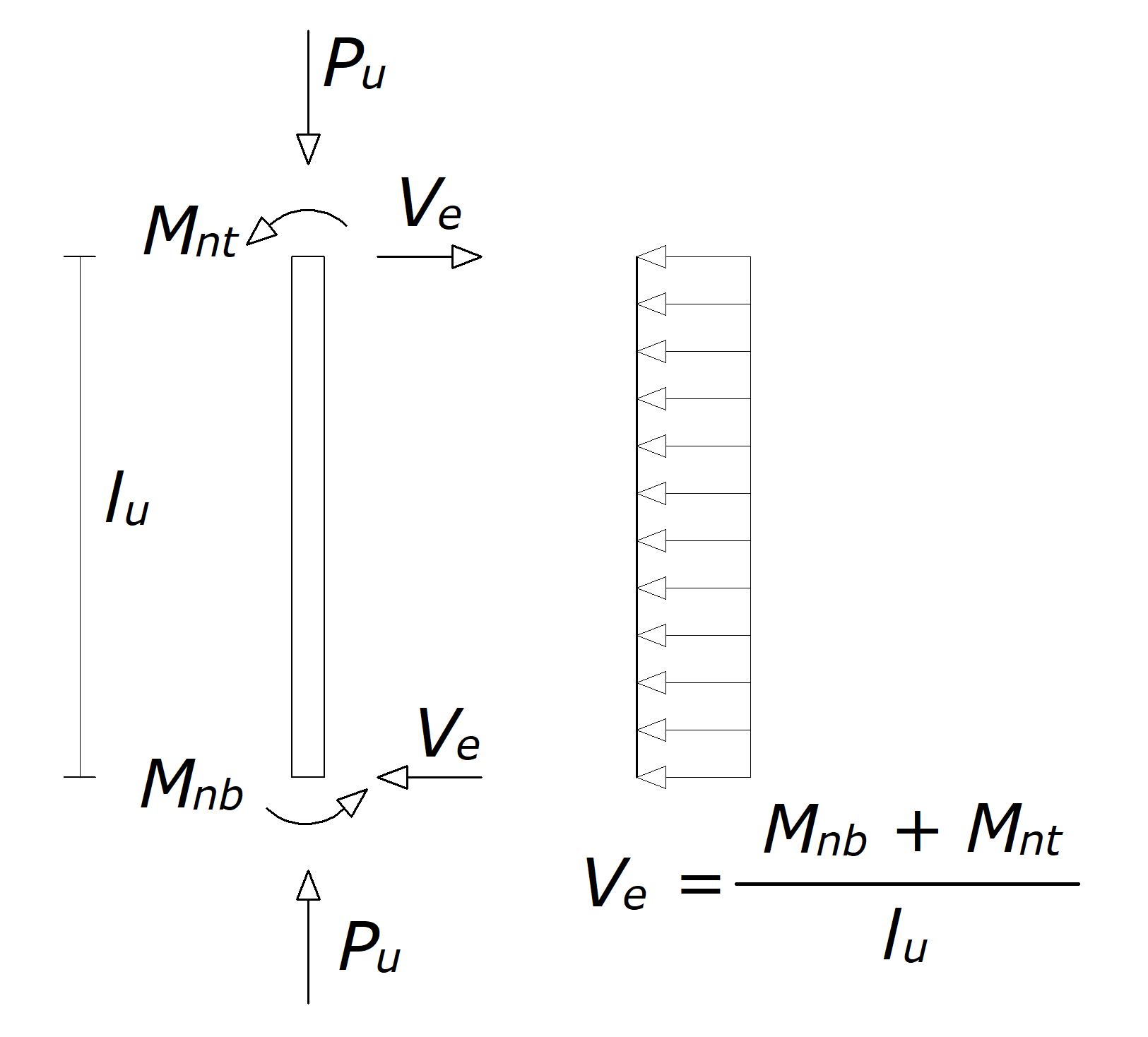
The design shear force Ve is calculated by considering the maximum forces that can be generated at the faces of the joints at each end of the column. These joint forces are calculated using the maximum probable flexural strength, Mpr. Two different capacity shear forces are calculated using Mpr for each direction (major and minor).
-
The first is based on the maximum probable moment strength of the column (Vec).
-
The second is computed from the maximum probable moment strengths of the beams framing into the column (Veb).
The design shear force Ve, is taken as the minimum of these two values but never less than the factored shear obtained from the design load combination.
Moment strengths are to be determined using a strength reduction factor, ϕ of 1.0 and reinforcement with an effective yield stress equal to 1.25fy.
'%3e%3cg transform='translate(167%2c0)'%3e%3cg transform='translate(-13%2c0)'%3e%3cg transform='translate(0%2c21)'%3e%3cuse xlink:href='%23MJMATHI-56' x='0' y='0'%3e%3c/use%3e%3cuse transform='scale(0.707)' xlink:href='%23MJMATHI-65' x='825' y='-213'%3e%3c/use%3e%3cuse xlink:href='%23MJMAIN-3D' x='1291' y='0'%3e%3c/use%3e%3cuse xlink:href='%23MJSZ2-5B' x='2347' y='-1'%3e%3c/use%3e%3cg transform='translate(2819%2c0)'%3e%3cuse xlink:href='%23MJMATHI-56' x='0' y='0'%3e%3c/use%3e%3cuse transform='scale(0.707)' xlink:href='%23MJMATHI-63' x='1167' y='500'%3e%3c/use%3e%3cuse transform='scale(0.707)' xlink:href='%23MJMATHI-65' x='825' y='-212'%3e%3c/use%3e%3c/g%3e%3cuse xlink:href='%23MJMAIN-2C' x='4607' y='0'%3e%3c/use%3e%3cg transform='translate(5608%2c0)'%3e%3cuse xlink:href='%23MJMATHI-56' x='0' y='0'%3e%3c/use%3e%3cuse transform='scale(0.707)' xlink:href='%23MJMATHI-62' x='1167' y='499'%3e%3c/use%3e%3cuse transform='scale(0.707)' xlink:href='%23MJMATHI-65' x='825' y='-212'%3e%3c/use%3e%3c/g%3e%3cg transform='translate(6837%2c0)'%3e%3cuse xlink:href='%23MJSZ2-5D' x='0' y='-1'%3e%3c/use%3e%3cg transform='translate(472%2c-686)'%3e%3cuse transform='scale(0.707)' xlink:href='%23MJMATHI-6D' x='0' y='0'%3e%3c/use%3e%3cuse transform='scale(0.707)' xlink:href='%23MJMATHI-69' x='878' y='0'%3e%3c/use%3e%3cuse transform='scale(0.707)' xlink:href='%23MJMATHI-6E' x='1224' y='0'%3e%3c/use%3e%3c/g%3e%3c/g%3e%3cuse xlink:href='%23MJMAIN-2265' x='8977' y='0'%3e%3c/use%3e%3cg transform='translate(10033%2c0)'%3e%3cuse xlink:href='%23MJMATHI-56' x='0' y='0'%3e%3c/use%3e%3cg transform='translate(583%2c-155)'%3e%3cuse transform='scale(0.707)' xlink:href='%23MJMATHI-75' x='0' y='0'%3e%3c/use%3e%3cuse transform='scale(0.707)' xlink:href='%23MJMAIN-2C' x='572' y='0'%3e%3c/use%3e%3cuse transform='scale(0.707)' xlink:href='%23MJMATHI-66' x='851' y='0'%3e%3c/use%3e%3cuse transform='scale(0.707)' xlink:href='%23MJMATHI-61' x='1401' y='0'%3e%3c/use%3e%3cuse transform='scale(0.707)' xlink:href='%23MJMATHI-63' x='1930' y='0'%3e%3c/use%3e%3cuse transform='scale(0.707)' xlink:href='%23MJMATHI-74' x='2364' y='0'%3e%3c/use%3e%3cuse transform='scale(0.707)' xlink:href='%23MJMATHI-6F' x='2725' y='0'%3e%3c/use%3e%3cuse transform='scale(0.707)' xlink:href='%23MJMATHI-72' x='3211' y='0'%3e%3c/use%3e%3cuse transform='scale(0.707)' xlink:href='%23MJMATHI-65' x='3662' y='0'%3e%3c/use%3e%3cuse transform='scale(0.707)' xlink:href='%23MJMATHI-64' x='4129' y='0'%3e%3c/use%3e%3c/g%3e%3c/g%3e%3c/g%3e%3c/g%3e%3c/g%3e%3c/g%3e%3c/svg%3e)
When calculating the capacity shear of the column, Vec, the maximum possible flexural strength at the two ends of the column is calculated for the existing factored axial load, Pu. As shown in ACI Figure R18.6.5, the Counter-clockwise rotation of the joint at one end and the associated clockwise rotation of the other joint produces one shear force. In other words, the shear force is determined from a free-body diagram obtained by cutting the column ends, with end, moments assumed equal to the nominal moment strengths. This situation is calculated for both clockwise and counter-clockwise directions, and the maximum value obtained from these two shear forces is taken as Vec.
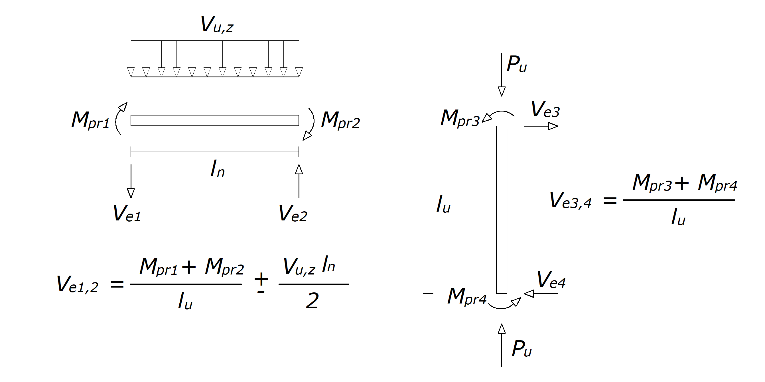
'%3e%3cg transform='translate(167%2c0)'%3e%3cg transform='translate(-13%2c0)'%3e%3cg transform='translate(0%2c21)'%3e%3cuse xlink:href='%23MJMATHI-56' x='0' y='0'%3e%3c/use%3e%3cuse transform='scale(0.707)' xlink:href='%23MJMATHI-63' x='1167' y='500'%3e%3c/use%3e%3cuse transform='scale(0.707)' xlink:href='%23MJMATHI-65' x='825' y='-212'%3e%3c/use%3e%3cuse xlink:href='%23MJMAIN-3D' x='1509' y='0'%3e%3c/use%3e%3cg transform='translate(2565%2c0)'%3e%3cuse xlink:href='%23MJMATHI-56' x='0' y='0'%3e%3c/use%3e%3cuse transform='scale(0.707)' xlink:href='%23MJMATHI-63' x='1167' y='500'%3e%3c/use%3e%3cg transform='translate(583%2c-307)'%3e%3cuse transform='scale(0.707)' xlink:href='%23MJMATHI-65' x='0' y='0'%3e%3c/use%3e%3cuse transform='scale(0.707)' xlink:href='%23MJMAIN-33' x='466' y='0'%3e%3c/use%3e%3c/g%3e%3c/g%3e%3cuse xlink:href='%23MJMAIN-3D' x='4210' y='0'%3e%3c/use%3e%3cg transform='translate(5267%2c0)'%3e%3cuse xlink:href='%23MJMATHI-56' x='0' y='0'%3e%3c/use%3e%3cuse transform='scale(0.707)' xlink:href='%23MJMATHI-63' x='1167' y='500'%3e%3c/use%3e%3cg transform='translate(583%2c-315)'%3e%3cuse transform='scale(0.707)' xlink:href='%23MJMATHI-65' x='0' y='0'%3e%3c/use%3e%3cuse transform='scale(0.707)' xlink:href='%23MJMAIN-34' x='466' y='0'%3e%3c/use%3e%3c/g%3e%3c/g%3e%3cuse xlink:href='%23MJMAIN-3D' x='6912' y='0'%3e%3c/use%3e%3cuse xlink:href='%23MJSZ2-5B' x='7968' y='-1'%3e%3c/use%3e%3cuse xlink:href='%23MJMAIN-28' x='8441' y='0'%3e%3c/use%3e%3cg transform='translate(8830%2c0)'%3e%3cuse xlink:href='%23MJMATHI-56' x='0' y='0'%3e%3c/use%3e%3cuse transform='scale(0.707)' xlink:href='%23MJMATHI-63' x='1167' y='500'%3e%3c/use%3e%3cg transform='translate(583%2c-307)'%3e%3cuse transform='scale(0.707)' xlink:href='%23MJMATHI-65' x='0' y='0'%3e%3c/use%3e%3cuse transform='scale(0.707)' xlink:href='%23MJMAIN-33' x='466' y='0'%3e%3c/use%3e%3c/g%3e%3c/g%3e%3cg transform='translate(10197%2c0)'%3e%3cuse xlink:href='%23MJMAIN-29' x='0' y='0'%3e%3c/use%3e%3cuse transform='scale(0.707)' xlink:href='%23MJMAIN-31' x='550' y='-213'%3e%3c/use%3e%3c/g%3e%3cuse xlink:href='%23MJMAIN-2C' x='11596' y='0'%3e%3c/use%3e%3cuse xlink:href='%23MJMAIN-28' x='12597' y='0'%3e%3c/use%3e%3cg transform='translate(12987%2c0)'%3e%3cuse xlink:href='%23MJMATHI-56' x='0' y='0'%3e%3c/use%3e%3cuse transform='scale(0.707)' xlink:href='%23MJMATHI-63' x='1167' y='500'%3e%3c/use%3e%3cg transform='translate(583%2c-307)'%3e%3cuse transform='scale(0.707)' xlink:href='%23MJMATHI-65' x='0' y='0'%3e%3c/use%3e%3cuse transform='scale(0.707)' xlink:href='%23MJMAIN-33' x='466' y='0'%3e%3c/use%3e%3c/g%3e%3c/g%3e%3cg transform='translate(14354%2c0)'%3e%3cuse xlink:href='%23MJMAIN-29' x='0' y='0'%3e%3c/use%3e%3cuse transform='scale(0.707)' xlink:href='%23MJMAIN-32' x='550' y='-213'%3e%3c/use%3e%3c/g%3e%3cg transform='translate(15197%2c0)'%3e%3cuse xlink:href='%23MJSZ2-5D' x='0' y='-1'%3e%3c/use%3e%3cg transform='translate(472%2c-686)'%3e%3cuse transform='scale(0.707)' xlink:href='%23MJMATHI-6D' x='0' y='0'%3e%3c/use%3e%3cuse transform='scale(0.707)' xlink:href='%23MJMATHI-61' x='878' y='0'%3e%3c/use%3e%3cuse transform='scale(0.707)' xlink:href='%23MJMATHI-78' x='1408' y='0'%3e%3c/use%3e%3c/g%3e%3c/g%3e%3c/g%3e%3c/g%3e%3c/g%3e%3c/g%3e%3c/svg%3e)
'%3e%3cg transform='translate(167%2c0)'%3e%3cg transform='translate(-13%2c0)'%3e%3cg transform='translate(0%2c-69)'%3e%3cuse xlink:href='%23MJSZ2-28' x='0' y='-1'%3e%3c/use%3e%3cg transform='translate(597%2c0)'%3e%3cuse xlink:href='%23MJMATHI-56' x='0' y='0'%3e%3c/use%3e%3cuse transform='scale(0.707)' xlink:href='%23MJMATHI-63' x='1167' y='500'%3e%3c/use%3e%3cg transform='translate(583%2c-307)'%3e%3cuse transform='scale(0.707)' xlink:href='%23MJMATHI-65' x='0' y='0'%3e%3c/use%3e%3cuse transform='scale(0.707)' xlink:href='%23MJMAIN-33' x='466' y='0'%3e%3c/use%3e%3c/g%3e%3c/g%3e%3cg transform='translate(1964%2c0)'%3e%3cuse xlink:href='%23MJSZ2-29' x='0' y='-1'%3e%3c/use%3e%3cuse transform='scale(0.707)' xlink:href='%23MJMAIN-31' x='844' y='-970'%3e%3c/use%3e%3c/g%3e%3cuse xlink:href='%23MJMAIN-3D' x='3293' y='0'%3e%3c/use%3e%3cuse xlink:href='%23MJSZ2-28' x='4350' y='-1'%3e%3c/use%3e%3cg transform='translate(4947%2c0)'%3e%3cuse xlink:href='%23MJMATHI-56' x='0' y='0'%3e%3c/use%3e%3cuse transform='scale(0.707)' xlink:href='%23MJMATHI-63' x='1167' y='500'%3e%3c/use%3e%3cg transform='translate(583%2c-315)'%3e%3cuse transform='scale(0.707)' xlink:href='%23MJMATHI-65' x='0' y='0'%3e%3c/use%3e%3cuse transform='scale(0.707)' xlink:href='%23MJMAIN-34' x='466' y='0'%3e%3c/use%3e%3c/g%3e%3c/g%3e%3cg transform='translate(6315%2c0)'%3e%3cuse xlink:href='%23MJSZ2-29' x='0' y='-1'%3e%3c/use%3e%3cuse transform='scale(0.707)' xlink:href='%23MJMAIN-31' x='844' y='-970'%3e%3c/use%3e%3c/g%3e%3cuse xlink:href='%23MJMAIN-3D' x='7644' y='0'%3e%3c/use%3e%3cg transform='translate(8422%2c0)'%3e%3cg transform='translate(397%2c0)'%3e%3crect stroke='none' width='3639' height='60' x='0' y='220'%3e%3c/rect%3e%3cg transform='translate(60%2c739)'%3e%3cuse transform='scale(0.707)' xlink:href='%23MJMATHI-4D' x='0' y='0'%3e%3c/use%3e%3cuse transform='scale(0.5)' xlink:href='%23MJMAIN-2212' x='1521' y='582'%3e%3c/use%3e%3cg transform='translate(686%2c-211)'%3e%3cuse transform='scale(0.5)' xlink:href='%23MJMATHI-70' x='0' y='0'%3e%3c/use%3e%3cuse transform='scale(0.5)' xlink:href='%23MJMATHI-72' x='503' y='0'%3e%3c/use%3e%3cuse transform='scale(0.5)' xlink:href='%23MJMAIN-33' x='955' y='0'%3e%3c/use%3e%3c/g%3e%3cuse transform='scale(0.707)' xlink:href='%23MJMAIN-2B' x='2099' y='0'%3e%3c/use%3e%3cg transform='translate(2035%2c0)'%3e%3cuse transform='scale(0.707)' xlink:href='%23MJMATHI-4D' x='0' y='0'%3e%3c/use%3e%3cuse transform='scale(0.5)' xlink:href='%23MJMAIN-2B' x='1521' y='582'%3e%3c/use%3e%3cg transform='translate(686%2c-217)'%3e%3cuse transform='scale(0.5)' xlink:href='%23MJMATHI-70' x='0' y='0'%3e%3c/use%3e%3cuse transform='scale(0.5)' xlink:href='%23MJMATHI-72' x='503' y='0'%3e%3c/use%3e%3cuse transform='scale(0.5)' xlink:href='%23MJMAIN-34' x='955' y='0'%3e%3c/use%3e%3c/g%3e%3c/g%3e%3c/g%3e%3cg transform='translate(1535%2c-418)'%3e%3cuse transform='scale(0.707)' xlink:href='%23MJMATHI-6C' x='0' y='0'%3e%3c/use%3e%3cuse transform='scale(0.5)' xlink:href='%23MJMATHI-75' x='422' y='-213'%3e%3c/use%3e%3c/g%3e%3c/g%3e%3c/g%3e%3cuse xlink:href='%23MJSZ2-28' x='18969' y='-1'%3e%3c/use%3e%3cg transform='translate(19566%2c0)'%3e%3cuse xlink:href='%23MJMATHI-56' x='0' y='0'%3e%3c/use%3e%3cuse transform='scale(0.707)' xlink:href='%23MJMATHI-63' x='1167' y='500'%3e%3c/use%3e%3cg transform='translate(583%2c-307)'%3e%3cuse transform='scale(0.707)' xlink:href='%23MJMATHI-65' x='0' y='0'%3e%3c/use%3e%3cuse transform='scale(0.707)' xlink:href='%23MJMAIN-33' x='466' y='0'%3e%3c/use%3e%3c/g%3e%3c/g%3e%3cg transform='translate(20934%2c0)'%3e%3cuse xlink:href='%23MJSZ2-29' x='0' y='-1'%3e%3c/use%3e%3cuse transform='scale(0.707)' xlink:href='%23MJMAIN-32' x='844' y='-970'%3e%3c/use%3e%3c/g%3e%3cuse xlink:href='%23MJMAIN-3D' x='22263' y='0'%3e%3c/use%3e%3cuse xlink:href='%23MJSZ2-28' x='23319' y='-1'%3e%3c/use%3e%3cg transform='translate(23916%2c0)'%3e%3cuse xlink:href='%23MJMATHI-56' x='0' y='0'%3e%3c/use%3e%3cuse transform='scale(0.707)' xlink:href='%23MJMATHI-63' x='1167' y='500'%3e%3c/use%3e%3cg transform='translate(583%2c-315)'%3e%3cuse transform='scale(0.707)' xlink:href='%23MJMATHI-65' x='0' y='0'%3e%3c/use%3e%3cuse transform='scale(0.707)' xlink:href='%23MJMAIN-34' x='466' y='0'%3e%3c/use%3e%3c/g%3e%3c/g%3e%3cg transform='translate(25284%2c0)'%3e%3cuse xlink:href='%23MJSZ2-29' x='0' y='-1'%3e%3c/use%3e%3cuse transform='scale(0.707)' xlink:href='%23MJMAIN-32' x='844' y='-970'%3e%3c/use%3e%3c/g%3e%3cuse xlink:href='%23MJMAIN-3D' x='26613' y='0'%3e%3c/use%3e%3cg transform='translate(27391%2c0)'%3e%3cg transform='translate(397%2c0)'%3e%3crect stroke='none' width='3639' height='60' x='0' y='220'%3e%3c/rect%3e%3cg transform='translate(60%2c739)'%3e%3cuse transform='scale(0.707)' xlink:href='%23MJMATHI-4D' x='0' y='0'%3e%3c/use%3e%3cuse transform='scale(0.5)' xlink:href='%23MJMAIN-2B' x='1521' y='582'%3e%3c/use%3e%3cg transform='translate(686%2c-211)'%3e%3cuse transform='scale(0.5)' xlink:href='%23MJMATHI-70' x='0' y='0'%3e%3c/use%3e%3cuse transform='scale(0.5)' xlink:href='%23MJMATHI-72' x='503' y='0'%3e%3c/use%3e%3cuse transform='scale(0.5)' xlink:href='%23MJMAIN-33' x='955' y='0'%3e%3c/use%3e%3c/g%3e%3cuse transform='scale(0.707)' xlink:href='%23MJMAIN-2B' x='2099' y='0'%3e%3c/use%3e%3cg transform='translate(2035%2c0)'%3e%3cuse transform='scale(0.707)' xlink:href='%23MJMATHI-4D' x='0' y='0'%3e%3c/use%3e%3cuse transform='scale(0.5)' xlink:href='%23MJMAIN-2212' x='1521' y='582'%3e%3c/use%3e%3cg transform='translate(686%2c-217)'%3e%3cuse transform='scale(0.5)' xlink:href='%23MJMATHI-70' x='0' y='0'%3e%3c/use%3e%3cuse transform='scale(0.5)' xlink:href='%23MJMATHI-72' x='503' y='0'%3e%3c/use%3e%3cuse transform='scale(0.5)' xlink:href='%23MJMAIN-34' x='955' y='0'%3e%3c/use%3e%3c/g%3e%3c/g%3e%3c/g%3e%3cg transform='translate(1535%2c-418)'%3e%3cuse transform='scale(0.707)' xlink:href='%23MJMATHI-6C' x='0' y='0'%3e%3c/use%3e%3cuse transform='scale(0.5)' xlink:href='%23MJMATHI-75' x='422' y='-213'%3e%3c/use%3e%3c/g%3e%3c/g%3e%3c/g%3e%3c/g%3e%3c/g%3e%3c/g%3e%3c/g%3e%3c/svg%3e)
The maximum possible positive and negative moment strengths of the column, Mpr3+, and Mpr4-, in a particular direction under the effect of the axial force Pu is calculated using the three-dimensional interaction surface in the corresponding direction. Mpr3 and Mpr4 are calculated by using a strength reduction factor, ϕ of 1.0, and longitudinal reinforcement with an effective yield stress equal to 1.25fy.
When calculating the capacity shear of the column based on the flexural strength of the beams framing into it, Veb, the maximum possible positive and negative moment forces of each beam frame to the upper joint of the column are calculated. Then the sum of the beam moments considered separately for both clockwise and counter-clockwise rotations is calculated as resistance to joint rotation.
Possible Mpr values that can occur at a joint are shown in the picture above. In this case, the capacity shear of the column based on the flexural strength of the beams framing into it, Veb, is calculated as follows.
'%3e%3cg transform='translate(167%2c0)'%3e%3cg transform='translate(-13%2c0)'%3e%3cg transform='translate(0%2c21)'%3e%3cuse xlink:href='%23MJMATHI-56' x='0' y='0'%3e%3c/use%3e%3cuse transform='scale(0.707)' xlink:href='%23MJMATHI-62' x='1167' y='499'%3e%3c/use%3e%3cuse transform='scale(0.707)' xlink:href='%23MJMATHI-65' x='825' y='-212'%3e%3c/use%3e%3cuse xlink:href='%23MJMAIN-3D' x='1506' y='0'%3e%3c/use%3e%3cuse xlink:href='%23MJSZ2-5B' x='2563' y='-1'%3e%3c/use%3e%3cg transform='translate(3035%2c0)'%3e%3cuse xlink:href='%23MJMATHI-56' x='0' y='0'%3e%3c/use%3e%3cuse transform='scale(0.707)' xlink:href='%23MJMATHI-62' x='1167' y='499'%3e%3c/use%3e%3cg transform='translate(583%2c-308)'%3e%3cuse transform='scale(0.707)' xlink:href='%23MJMATHI-65' x='0' y='0'%3e%3c/use%3e%3cuse transform='scale(0.707)' xlink:href='%23MJMAIN-31' x='466' y='0'%3e%3c/use%3e%3c/g%3e%3c/g%3e%3cuse xlink:href='%23MJMAIN-2C' x='4958' y='0'%3e%3c/use%3e%3cg transform='translate(5959%2c0)'%3e%3cuse xlink:href='%23MJMATHI-56' x='0' y='0'%3e%3c/use%3e%3cuse transform='scale(0.707)' xlink:href='%23MJMATHI-62' x='1167' y='499'%3e%3c/use%3e%3cg transform='translate(583%2c-308)'%3e%3cuse transform='scale(0.707)' xlink:href='%23MJMATHI-65' x='0' y='0'%3e%3c/use%3e%3cuse transform='scale(0.707)' xlink:href='%23MJMAIN-32' x='466' y='0'%3e%3c/use%3e%3c/g%3e%3c/g%3e%3cg transform='translate(7326%2c0)'%3e%3cuse xlink:href='%23MJSZ2-5D' x='0' y='-1'%3e%3c/use%3e%3cg transform='translate(472%2c-686)'%3e%3cuse transform='scale(0.707)' xlink:href='%23MJMATHI-6D' x='0' y='0'%3e%3c/use%3e%3cuse transform='scale(0.707)' xlink:href='%23MJMATHI-61' x='878' y='0'%3e%3c/use%3e%3cuse transform='scale(0.707)' xlink:href='%23MJMATHI-78' x='1408' y='0'%3e%3c/use%3e%3c/g%3e%3c/g%3e%3c/g%3e%3c/g%3e%3c/g%3e%3c/g%3e%3c/svg%3e)
'%3e%3cg transform='translate(167%2c0)'%3e%3cg transform='translate(-13%2c0)'%3e%3cg transform='translate(0%2c-144)'%3e%3cuse xlink:href='%23MJMATHI-56' x='0' y='0'%3e%3c/use%3e%3cuse transform='scale(0.707)' xlink:href='%23MJMATHI-62' x='1167' y='499'%3e%3c/use%3e%3cg transform='translate(583%2c-308)'%3e%3cuse transform='scale(0.707)' xlink:href='%23MJMATHI-65' x='0' y='0'%3e%3c/use%3e%3cuse transform='scale(0.707)' xlink:href='%23MJMAIN-31' x='466' y='0'%3e%3c/use%3e%3c/g%3e%3cuse xlink:href='%23MJMAIN-3D' x='1645' y='0'%3e%3c/use%3e%3cg transform='translate(2423%2c0)'%3e%3cg transform='translate(397%2c0)'%3e%3crect stroke='none' width='3639' height='60' x='0' y='220'%3e%3c/rect%3e%3cg transform='translate(60%2c733)'%3e%3cuse transform='scale(0.707)' xlink:href='%23MJMATHI-4D' x='0' y='0'%3e%3c/use%3e%3cuse transform='scale(0.5)' xlink:href='%23MJMAIN-2212' x='1521' y='582'%3e%3c/use%3e%3cg transform='translate(686%2c-211)'%3e%3cuse transform='scale(0.5)' xlink:href='%23MJMATHI-70' x='0' y='0'%3e%3c/use%3e%3cuse transform='scale(0.5)' xlink:href='%23MJMATHI-72' x='503' y='0'%3e%3c/use%3e%3cuse transform='scale(0.5)' xlink:href='%23MJMAIN-31' x='955' y='0'%3e%3c/use%3e%3c/g%3e%3cuse transform='scale(0.707)' xlink:href='%23MJMAIN-2B' x='2099' y='0'%3e%3c/use%3e%3cg transform='translate(2035%2c0)'%3e%3cuse transform='scale(0.707)' xlink:href='%23MJMATHI-4D' x='0' y='0'%3e%3c/use%3e%3cuse transform='scale(0.5)' xlink:href='%23MJMAIN-2B' x='1521' y='582'%3e%3c/use%3e%3cg transform='translate(686%2c-211)'%3e%3cuse transform='scale(0.5)' xlink:href='%23MJMATHI-70' x='0' y='0'%3e%3c/use%3e%3cuse transform='scale(0.5)' xlink:href='%23MJMATHI-72' x='503' y='0'%3e%3c/use%3e%3cuse transform='scale(0.5)' xlink:href='%23MJMAIN-32' x='955' y='0'%3e%3c/use%3e%3c/g%3e%3c/g%3e%3c/g%3e%3cg transform='translate(1535%2c-418)'%3e%3cuse transform='scale(0.707)' xlink:href='%23MJMATHI-6C' x='0' y='0'%3e%3c/use%3e%3cuse transform='scale(0.5)' xlink:href='%23MJMATHI-75' x='422' y='-213'%3e%3c/use%3e%3c/g%3e%3c/g%3e%3c/g%3e%3cg transform='translate(12970%2c0)'%3e%3cuse xlink:href='%23MJMATHI-56' x='0' y='0'%3e%3c/use%3e%3cuse transform='scale(0.707)' xlink:href='%23MJMATHI-62' x='1167' y='499'%3e%3c/use%3e%3cg transform='translate(583%2c-308)'%3e%3cuse transform='scale(0.707)' xlink:href='%23MJMATHI-65' x='0' y='0'%3e%3c/use%3e%3cuse transform='scale(0.707)' xlink:href='%23MJMAIN-32' x='466' y='0'%3e%3c/use%3e%3c/g%3e%3c/g%3e%3cuse xlink:href='%23MJMAIN-3D' x='14615' y='0'%3e%3c/use%3e%3cg transform='translate(15393%2c0)'%3e%3cg transform='translate(397%2c0)'%3e%3crect stroke='none' width='3639' height='60' x='0' y='220'%3e%3c/rect%3e%3cg transform='translate(60%2c733)'%3e%3cuse transform='scale(0.707)' xlink:href='%23MJMATHI-4D' x='0' y='0'%3e%3c/use%3e%3cuse transform='scale(0.5)' xlink:href='%23MJMAIN-2B' x='1521' y='582'%3e%3c/use%3e%3cg transform='translate(686%2c-211)'%3e%3cuse transform='scale(0.5)' xlink:href='%23MJMATHI-70' x='0' y='0'%3e%3c/use%3e%3cuse transform='scale(0.5)' xlink:href='%23MJMATHI-72' x='503' y='0'%3e%3c/use%3e%3cuse transform='scale(0.5)' xlink:href='%23MJMAIN-31' x='955' y='0'%3e%3c/use%3e%3c/g%3e%3cuse transform='scale(0.707)' xlink:href='%23MJMAIN-2B' x='2099' y='0'%3e%3c/use%3e%3cg transform='translate(2035%2c0)'%3e%3cuse transform='scale(0.707)' xlink:href='%23MJMATHI-4D' x='0' y='0'%3e%3c/use%3e%3cuse transform='scale(0.5)' xlink:href='%23MJMAIN-2212' x='1521' y='582'%3e%3c/use%3e%3cg transform='translate(686%2c-211)'%3e%3cuse transform='scale(0.5)' xlink:href='%23MJMATHI-70' x='0' y='0'%3e%3c/use%3e%3cuse transform='scale(0.5)' xlink:href='%23MJMATHI-72' x='503' y='0'%3e%3c/use%3e%3cuse transform='scale(0.5)' xlink:href='%23MJMAIN-32' x='955' y='0'%3e%3c/use%3e%3c/g%3e%3c/g%3e%3c/g%3e%3cg transform='translate(1535%2c-418)'%3e%3cuse transform='scale(0.707)' xlink:href='%23MJMATHI-6C' x='0' y='0'%3e%3c/use%3e%3cuse transform='scale(0.5)' xlink:href='%23MJMATHI-75' x='422' y='-213'%3e%3c/use%3e%3c/g%3e%3c/g%3e%3c/g%3e%3c/g%3e%3c/g%3e%3c/g%3e%3c/g%3e%3c/svg%3e)
Mpr1 and Mpr2 values are beam moment resistance values with clockwise or counter-clockwise joint rotations.
According to ACI 18.7.6.2.1, if both two conditions given below occur, transverse reinforcement over the lengths lo should be designed to resist shear, assuming Vc=0.
-
The earthquake-induced shear force, calculated in accordance with ACI 18.7.6.1, is at least one-half of the maximum required shear strength within lo.
-
The factored axial compressive force Pu including earthquake effects, is less than Agfc′/10.