-
In buildings with basements surrounded by rigid walls from the outside, the selection of earthquake analysis is under user control, including two-load and single-load-state calculation methods.
-
According to the selected calculation method, the internal forces based on the design in buildings with basements are calculated automatically.
ICONS
|
D |
Extra Strength Coefficient |
|
D alt |
Strength Excess Coefficient applied to the lower part of the building |
|
D top |
Strength Excess Coefficient applied to the lower part of the building |
|
R |
Carrier System Behavior Coefficient |
|
R alt |
Structural System Behavior Coefficient applied to the lower part of the building |
|
(R a ) alt |
Earthquake Load Reduction Coefficient applied to the lower part of the building |
|
(R a ) n, alt |
Earthquake Load Reduction Coefficient applied to the lower part of the building in the nth vibration mode |
|
R üst |
Structural System Behavior Coefficient applied to the lower part of the building |
|
(R a ) upper |
Earthquake Load Reduction Coefficient applied to the upper part of the building |
|
(R a ) n, upper |
Earthquake Load Reduction Coefficient applied to the upper part of the building in the nth vibration mode |
In buildings with basements surrounded by rigid curtains, in the upper section above the basement floors and in the lower section where the basement floors are located, the internal forces based on the design are determined in two ways according to the following loading conditions.
-
Two-state calculation method
-
Single install case calculation method
Both loading conditions described above are used to determine earthquake effects. The internal forces based on the design described in this section are the earthquake effects found as a result of modal combination and earthquake analysis . After the earthquake effects are found, they are combined with other effects in accordance with TBDY Section 4.4.4 and loading combinations are created.
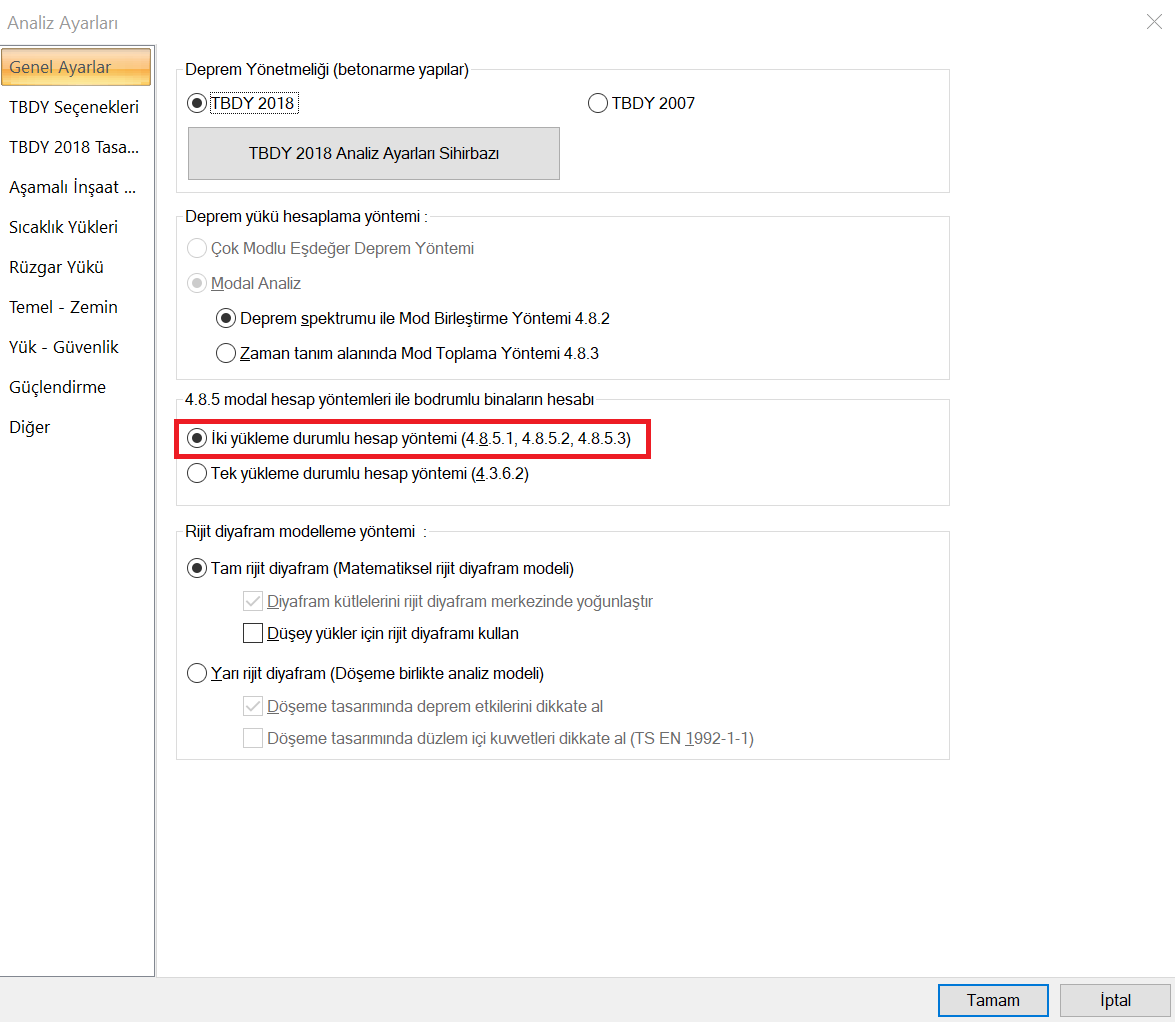
Two-state calculation method
The method described in Section 4.8.5 of TBDY is applied if the two-load calculation method is chosen in buildings with basements surrounded by rigid walls .
In the two-stage analysis method mentioned in 4.8.5 , the lower section (rigid basement floors) and the upper section are analyzed for two different situations in one model and the results are combined.
First loading state:
The whole structure model is created in the calculation of the internal forces based on the design that corresponds to the ductile behavior of the structural system elements in the upper section , but the lower section mass is not included in the modal combination analysis. The mass and rigidity of the superstructure elements and the lower section elements are considered only with the element stiffness. In this way, the internal force and displacements are obtained in both the upper section and the lower section as a result of the earthquake analysis with the mode combination . During the analysis, R and D coefficients suitable for the carrier system should be selected from Table 4.1 for the upper section . Design essential internal forces that correspond to the non-ductile behavior of the structural system elements in the upper sectionIt is obtained by multiplying the internal forces obtained as a result of the earthquake analysis with the mode combination in the first loading case with the top D. While obtaining internal forces based on the design, which correspond to the ductile or non-ductile behavior of the structural system elements in the
upper section , mode coupling and earthquake analysis are used. In this case, according to 4.10.1.3 , these internal forces are increased by multiplying the equivalent base shear force by the magnification factor .
Second loading situation:
In the earthquake analysis analysis with the modal combination in the lower part , the whole building model is created, but the upper part mass is not included in the calculation. While the stiffness and mass of the lower section elements are taken into account, only the element stiffness of the upper section elements are taken into account. In the lower part, internal forces based on the design against ductile behavior; It is taken as the sum of internal forces obtained from upper section and lower section analysis. Subsections wherein the structural elements of the non-ductile behavior to the corresponding design basis internal forces , the internal forces are obtained in the case of the second installation D received multiplied by the top of the internal forces are obtained in the lower part if the first loading 0.6D topIt is obtained by adding the product of by. For the subdivision (R alt / I) = 2.5 and D sub = 1.5.
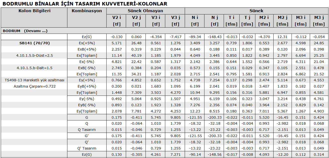
The figure below shows the internal force table of a column in the basement. Here Ex and Ey are internal forces from the first loading case, ExB and EyB from the second loading case.
For the account with two loading status, the option "Calculation method with two loading status" from the "Analysis Settings" command should be checked as follows.
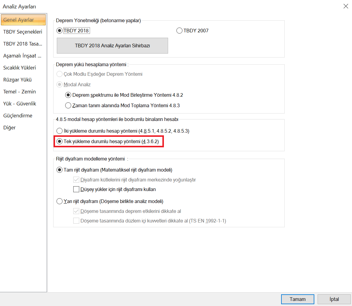
Single install case calculation method
In buildings with basements surrounded by rigid walls from the outside , the method described in Section 4.3.6 of TBDY is applied if the single-load calculation method is chosen .
The internal forces based on the design that correspond to the ductile behavior of the structural system elements in the upper section are the internal forces obtained as a result of the earthquake analysis by modal combination .
The upper portion wherein the structural elements corresponding to the non-ductile behavior of design basis internal forces and seismic analysis modal internal forces resulting from the D top with internal forces are obtained from the multiplication.
The internal forces based on the design that correspond to the ductile behavior of the structural system elements in the subsection are obtained by applying the Full Quadratic Combination rule, taking into account the (R a ) n, lower and coefficient while performing earthquake analysis with mode combination . The internal forces (R a ) n, sub and D n, sub- coefficients , which are the basis of the design, which correspond to the non-ductile behavior of the structural system elements in the lower section , are obtained by applying the Full Quadratic Combination rule.
The "Calculation method with single loading status" option is selected from the "Analysis Settings" command as shown in the picture below.