
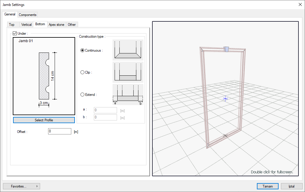
With the Jamb Settings command, settings such as profile selection, construction type, offset distance, material selection are accessed. Jamb settings vary according to the top, bottom, vertical and apex stone sections. According to the architectural design, those required from these sections are closed.
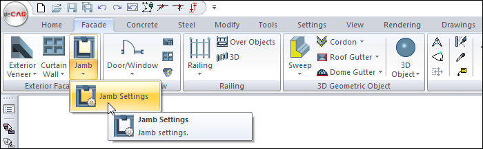
Location of the Jamb Settings Command
You can access it under the Ribbon menu, Facade tab, Exterior Facade title.
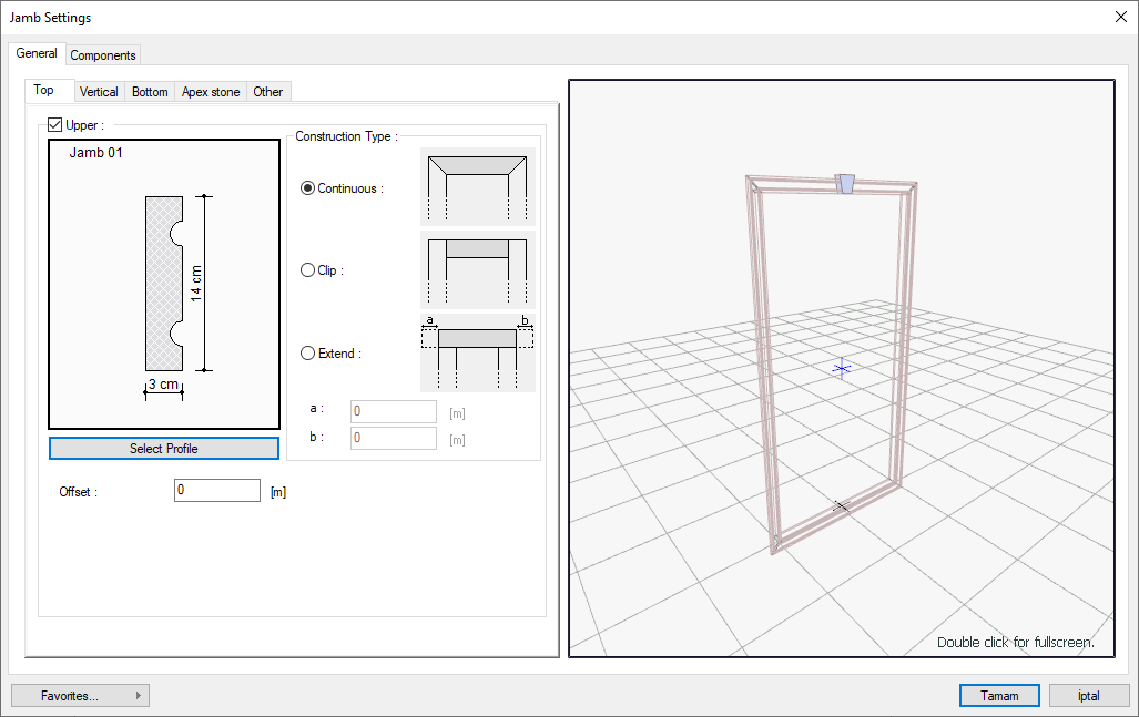
General Tab
Top Part
It is the section where the properties of the upper part of the jamb element are adjusted. The upper part refers to the upper part of the jamb object surrounding the door/window element.
|
Specifications |
|---|
|
Upper Draws or does not scratch the upper part of the jamb element. |
|
Profile preview 
A preview of the selections appears on the screen. |
|
Select profile Opens the profile archive. The profile you will use for the jamb is selected. |
|
Offset It determines how far the upper part of the jamb element will be formed from the upper part of the window/door element. If zero is given, the upper part of the jamb element is created adjacent to the upper part of the door/window element. You can shift the top piece farther by value this row. |
|
Continuous 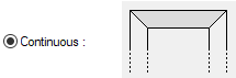
The upper part of the jamb element surrounds the window/door element in a continuous and continuous form. With this option, you create the jamb as a whole with the top and side parts. |
|
Clip 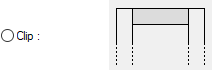
The upper part of the jamb element is separated from the side parts of the jamb. The upper part is formed as another part between the side parts. |
|
Extend 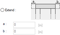
The upper part of the jamb element is separated from the side parts, and furthermore, the upper parts can be protruded to a certain length from the right and left. The extension values can be given in the lines named "a" and "b" in the dialog below. |
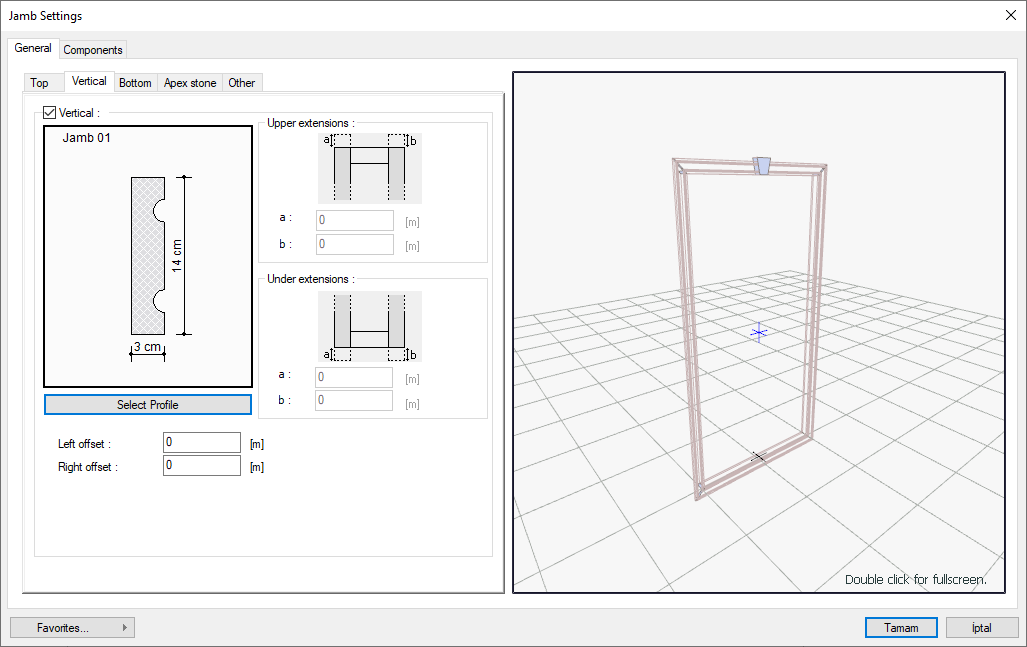
Vertical Part
It is the section where the properties of the vertical parts of the jamb element are adjusted. The vertical part refers to the side parts of the jamb object surrounding the door/window element.
|
Specifications |
|---|
|
Vertical Scratches or does not scratch the vertical parts of the jamb element. |
|
Profile preview 
A preview of the selections appears on the screen. |
|
Select profile Opens the profile archive. The profile you will use for the jamb is selected. |
|
Left offset Determines how far the vertical pieces of the jamb element will be formed from the window/door element. If zero is given, the left vertical part is created adjacent to the left part of the door/window element. By valuing this row, you can shift the left side part farther. |
|
Right offset It determines how far the vertical pieces of the jamb element will be formed from the window/door element. If zero is given, the right vertical part is created adjacent to the right part of the door/window element. You can shift the right side part farther by value this row. |
|
Upper extensions 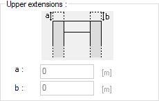
It becomes active if the upper part of the jamb element is created with the "cut" option. You can determine how much the vertical parts of the jamb will overflow on the top with the values you write in the lines a and b. |
|
Under extensions 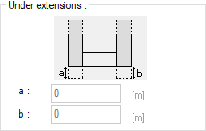
It becomes active if the lower part of the jamb element is created with the "cut" option. You can determine how much the vertical parts of the jamb will overflow at the bottom with the values you write in the lines a and b. |
Bottom Part
It is the tab where the properties of the lower part of the jamb element are set. The lower part refers to the lower part of the jamb object surrounding the door / window element.
|
Specifications |
|---|
|
Under Draws or does not draw the bottom part of the jamb element. |
|
Profile preview 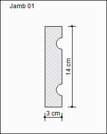
A preview of the selections appears on the screen. |
|
Select profile Opens the profile archive. The profile you will use for the jamb is selected. |
|
Offset It determines how far the bottom part of the jamb element will be formed from the bottom part of the window element. If zero is given, the bottom part of the jamb element is created adjacent to the bottom part of the window element. You can shift the bottom part farther by giving value to this row. |
|
Continuous 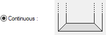
The bottom part of the jamb element surrounds the window element in a continuous and continuous form. With this option, you create the jamb as a whole with the bottom and vertical parts. |
|
Clip 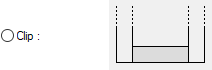
The bottom part of the jamb element is separated from the vertical parts of the jamb. The top part is formed as another part between the vertical parts. |
|
Extend 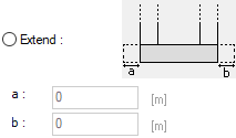
With this option, the bottom part of the jamb element is separated from the vertical parts and also the bottom parts can be protruded to a certain length from the right and left. The extension values can be given in the lines named "a" and "b" in the dialog below. |
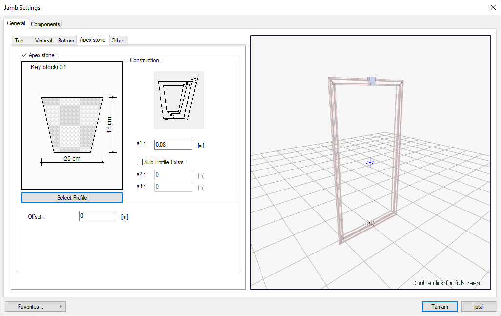
Apex Stone Part
This is the tab in which the properties of the key block part of the jamb element are set.
|
Specifications |
|---|
|
Apex stone If it is checked, the key block is placed at the top of the jamb object. |
|
Profile preview 
A preview of the selections appears on the screen. |
|
Select profile Opens the profile archive. The profile to be used for the key block is selected. |
|
Offset Determines how far the key block is created from the jamb element. You can shift the keystone by giving value to this row. |
|
Schematic drawing 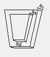
The locations of the values a1, a2 and a3 are shown in the schematic drawing. |
|
a1 It is the thickness of the key block. You can see the information about where this value is in the figure above. |
|
Sub profile exists Creates a second ledge by offsetting according to the values given from the key block. |
|
a2 It is the width of the bottom profile. You can see the information about where this value is in the figure above. |
|
a3 It is the thickness of the bottom profile. You can see the information about where this value is in the figure above. |
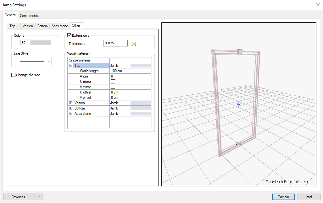
Other Part
|
Specifications |
|---|
|
Color The color of the jamb object is set. |
|
Extension Adjusts the thickness of the jamb in the area between the wall and the joinery. |
|
Line stype Sets the line type of the jamb object. |
|
Change dio side It takes the symmetry of the jamb object with respect to the wall axis. |
|
Material appearance 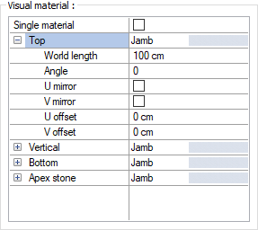
The material to be used on the top, vertical, bottom and apex stone parts of the jamb is selected from the list. Surfaces are covered with the selected material and displayed as such in renderings. Texture length is entered into the world length. For example; If 1 is entered, the selected material texture is taken as 1 meter and covered on the relevant walls. In the angle, the angle of the texture is entered. Touch the U and V offset. The motion value in the x and y plane is entered. With U and V mirroring, the texture is symmetrical with respect to the y and x planes. By selecting the single material option, the material selected in "Top" is used on all surfaces of the jamb. |
Components Tab
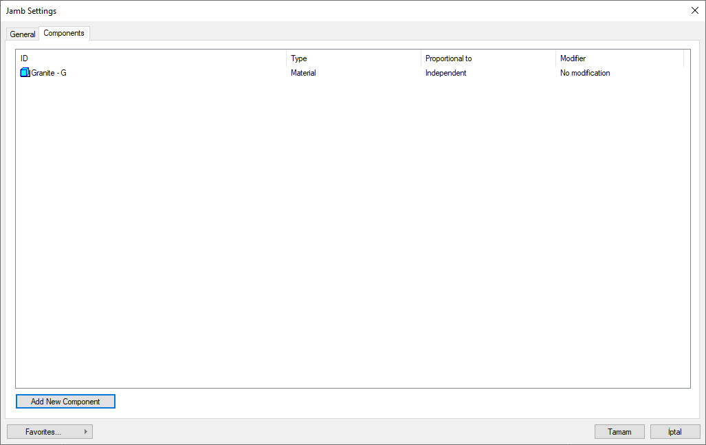
Add building components: Assigns the building materials defined for the detailed building components metering to the wall object.
-
Click the Add Building Component button.
-
The Component Selection dialog will open.
-
In this dialog, click the folder related to the material from the list on the left. Choose the material you want to use.
-
Set the parameters on the right.
-
Click the OK button. The "Component Selection" dialog will be closed. A summary line of the material will appear in the Building Components tab. More than one material assignment can be made to an object.
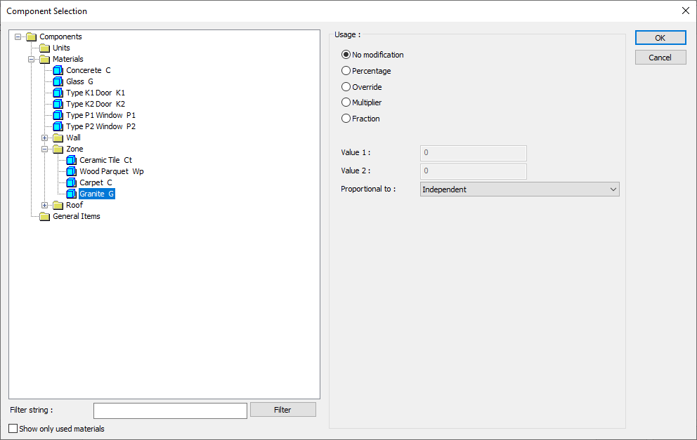
The parameters in the use section of the component selection dialog are:
No modification: The amount of material to be assigned for the object in question is marked when it is desired to be used in the size that was previously specified in the material definition.
Percentage: This line is marked when it is desired to be used with the percentage of the amount previously determined in the material definition, as much as the value entered in the "Value 1" line in the same dialog. For example, if the material quantity is 70, if the line “Value 1” says 40, it means the material amount will be used up to 40 * 70%.
Override: This line is marked so that the quantity entered in the “Value 1” line in the same dialog will be used instead of the quantity previously determined in the material definition.
Multiplier: This line is marked in order to use the value found at the end of the multiplication of the value entered in the "Value 1" line in the same dialog with the amount previously determined in the material definition.
Fraction: This line is marked so that the amount determined in the material definition before will be used as the fraction value created by the values entered in the "Value 1" and "Value 2" lines in the same dialog. "Value 1" is the denominator "Value 2" is the denominator.
Proportional to: It is determined to what scale-area, circumference, length etc.-, region-side area, top, edge etc.- the material will be proportioned to. The content of the proportional list box is automatically determined according to the object and the size of the material. For example, a different list will be created if an operation is made for the column, a different list will be created for the library, a different list for the volume, and a different list for the field.
Following are the lines that appear in the proportion list according to the jamb and material size.
|
Jamb |
||
|
Measure |
Listed |
Explanation |
|
Constant |
Independent |
It means that the length measure found while defining the material will be used exactly as the length value. |
|
Length |
Independent |
It means that the length measure found while defining the material will be used exactly as the length value. |
|
Length |
It means that the length of the material will be found by multiplying the length measurement found when defining the material and the length of the jamb. |
|
|
Area |
Independent |
It means that the area measure found while defining the material will be used exactly as the amount. |
|
Outside area |
It means that the area measure found when defining the material will be used by multiplying it with the jamb outside area. |
|
|
Volume |
Independent |
The volume measure found when defining the material will be used exactly as the volume of the material. |
|
Volume |
It means that the volume measure found when defining the material will be used by multiplying it by the volume of the jamb. |
|
|
Count
|
Independent |
The number measure found while defining the material will be used exactly as the material number. |
|
Count |
It means that the number measure found when defining the material will be multiplied by the number of jambs. |
|
Next Topic