
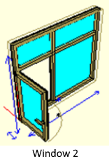
Window 2 is created by following the steps below.
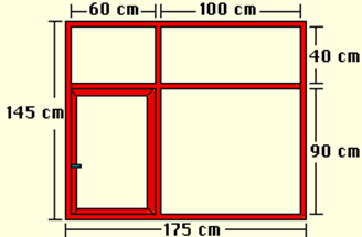
Planning on Paper
You can get the 2nd window by adding a wing to the 1st window created previously.
Click on the line Construction / Plan-Section-View Reset . To add a wing 1. Delete the glass object created for the window.
Wing Identification
-
Click the Jump to Support / Object Points row and select the crates and separators. The node points will appear.
-
Click the Line Drawing / Rectangular Case-Wing .
-
Identify your wing with reference to the enclosure internal nodes and the joints of the separators.
Drawing Arm and Connecting This Arm to the Case
ð Click on the Line Drawing / Polygon .
ð Draw the top view of the arm in the plan view.
-
Click on the Change / Extend line.
-
Click on the polygon.
-
Enter the values x = 0, y = 0, z = 0.3 from the dialog box that appears (You can do the extension by moving the extended part with the mouse, but it will be useful to enter values from the dialog box to ensure that the values are integers.)
You need to connect the extended arm to the wing, because after the fastening process, when the wing is turned as if the arm is a part of the wing, it will rotate with the wing without distorting its placement on the wing.
-
Click the Create / Set Up Frame-Wing Object Link line.
-
Click on the safe.
-
Click on arm.
Determining the Wing Rotation Axis
You can determine the axis around which the wings will rotate.
-
Click the Jump to Support / Object Points row.
-
Click Canada. The wing has become selected (Joints are visible. We will determine the rotation axis by jumping to these joints.).
-
Click the Change / Set Wing Axis row.
-
Click on the upper left node.
-
Click on the lower left node.
Not
Body Rotation Axis determination is the process of creating a line around which the case will rotate. This line can be drawn anywhere.
Adding Parameters
-
Click on the Construction / Add New Parameter row.
-
Enter the parameter name from the dialog that comes up.
-
Enter a number in degrees for the angle.
-
If the parameter is the opening angle , check the This Parameter is the door / window opening angle option.
-
Click OK button
Opening the Wing
-
Select the wing you want to open and enter its Properties .
-
Enter the name of the parameter you have created in the angle box or select the parameter by clicking the down arrow button next to the box.
-
Click the OK button.
Creating Material and Covering the Window with This Material
-
Click on the Construction / Add New Material row.
-
In the dialog that comes up, click and hold the Color box and select the appropriate color.
-
If you activate the Transparent option, all objects covered with that material will be included in the ideCAD Architectural transparently during rendering.
-
Name your material.
-
Click the Add button. The material will become active in the materials section at the bottom of the design tracking window.
-
Enter the Properties of the vault . Select the material you created in the Material section from the Parameters section .
-
Do the item assignment for all elements of the window.
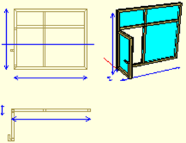
Creating Plan, Section and View Drawings
In order for the created window to appear on the plan, section, and view pages, these must be created before the dio is saved.
-
You can create your plan automatically by clicking on the Construction / Create Plan line.
-
You can automatically create your cross section by clicking on the Construct / Create Section line.
-
You can create your view automatically by clicking on the Construction / Create Appearance line.
Later, you can make any changes you want in 2 dimensions in plan, section and views and make detailing.
Next Topic
Related Topics