
Displaced axis rotation and total curvature demand values are calculated by using the yield moment, yield curvature, crushing moment and crushing curvature values calculated as a result of the moment curvature analysis. In linear performance analysis, the moment-curvature relation is found with the information level coefficient and the material models created by considering the existing material strengths.
-
Effective yield curvature ϕ y and effective yield moment M y in reinforced concrete elements are calculated automatically by moment-curvature analysis.
ICONS
E = Concrete modulus of elasticity
h = Section height
I = Moment of inertia
L p = Plastic hinge length
l c = Element net opening
M y = Effective yield moment
M yi = Effective yield momentat i end
M yj = Effective yield moment at j end
Δ = Element translation between nodes
ϕ y = Flow curvature
ϕ t = Total curvature
θ p =Plastic rotation demand
θ y = Flow rotation
θ yi = flow rotation at end i
θ yj = flow rotation at end j
θ k = Displaced axis rotation
θ ki = displaced axis rotation at end i
A representative representation of the graph created as a result of Moment-curvature analysis in reinforced concrete systems is given below. While analyzing moment curvature in determining the earthquake performance with the Assessment and Design (ŞGDT) approach of existing structures , material models are used considering the Knowledge Level Coefficient and Available Material Strengths ( 15.5.4.4 ).
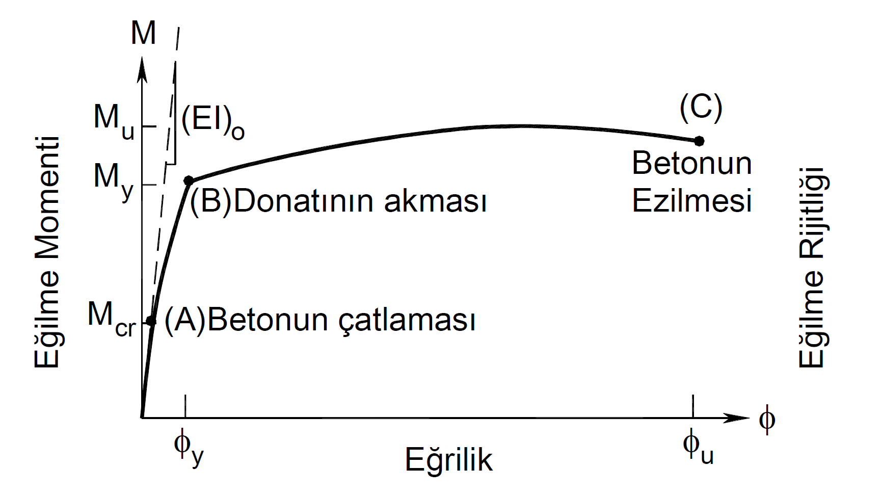
In the graph above, point (B) is the point where the tensile reinforcement flows. The moment value at this point is called the yield moment M y and the curvature value is called the yield curvature ϕ y .
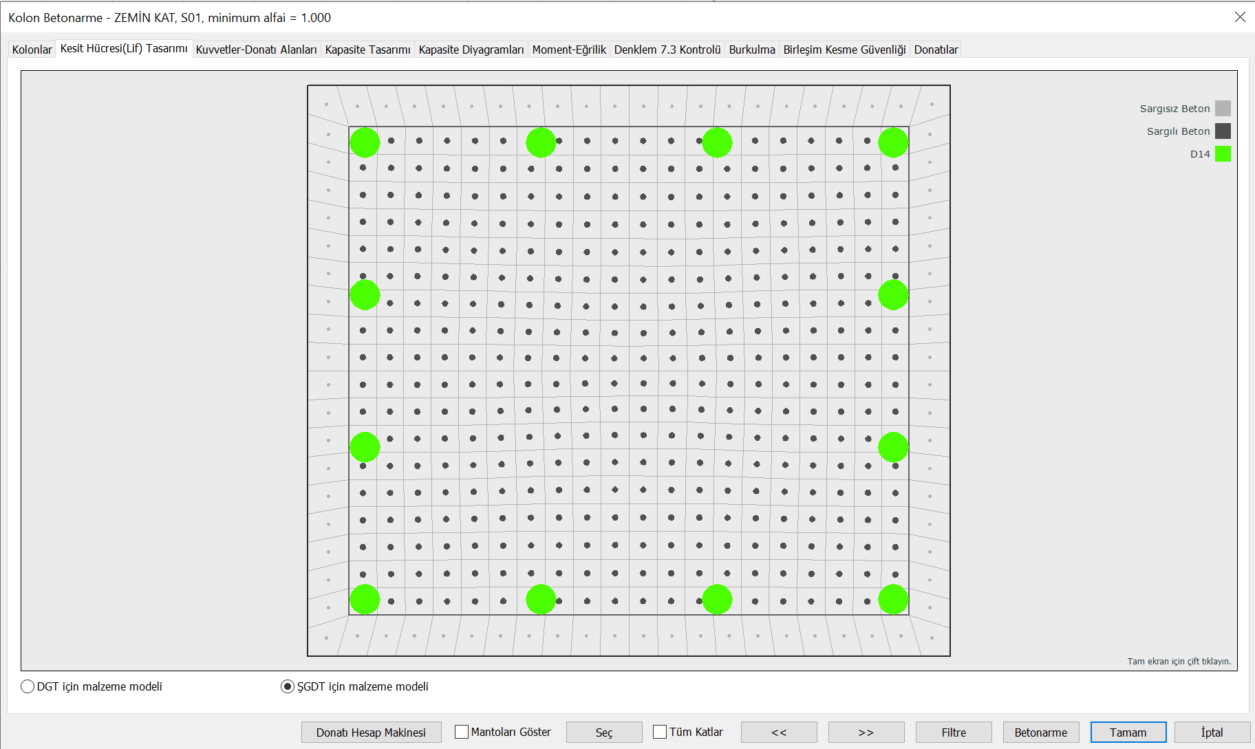
The following picture shows the section cell-fiber (fiber) model used in moment-curvature analysis. Here, the fibers shown in light gray are defined by the unbound concrete, the fibers shown in dark gray with the confined concrete, and the fibers shown in green with the reinforcement model. While creating these material models, Knowledge Level Coefficient and Available Material Strengths are taken into consideration.
After the material model definition, the moment-curvature analysis of the section is made and a moment-curvature graph is drawn as shown below.
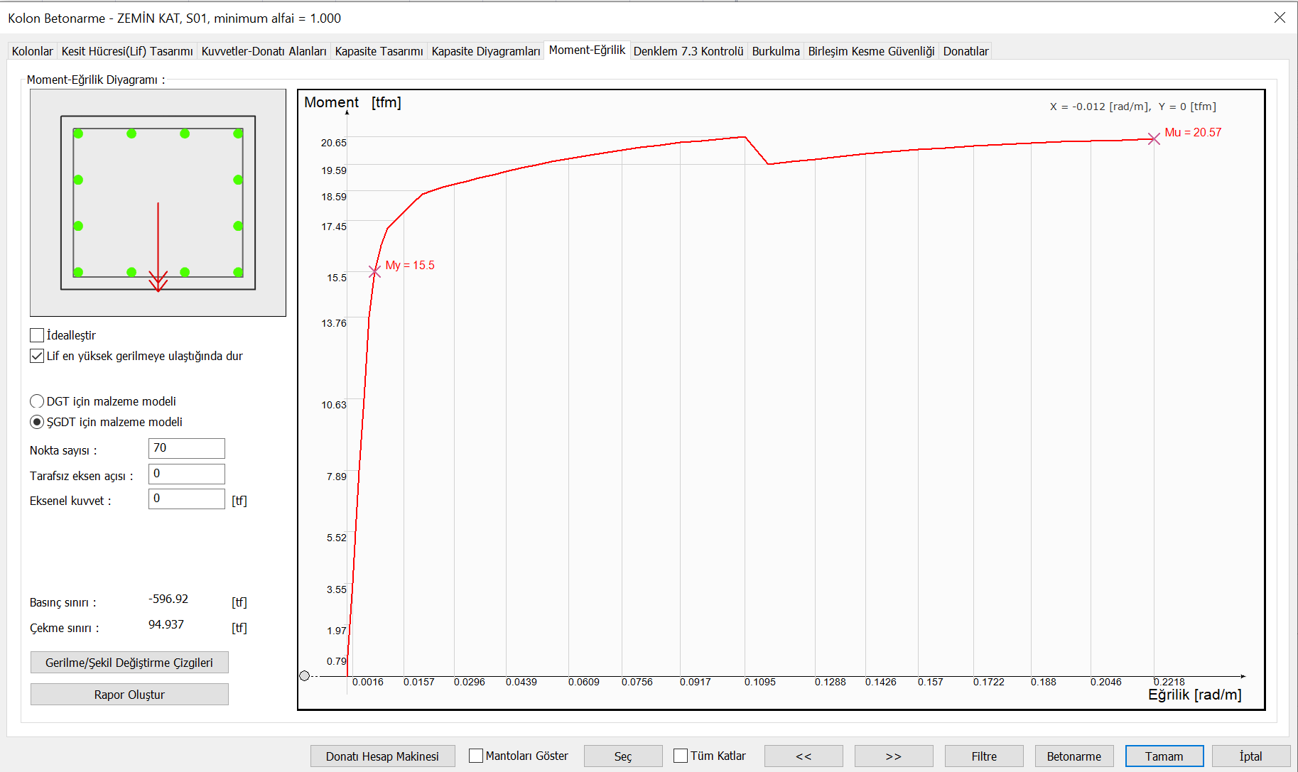
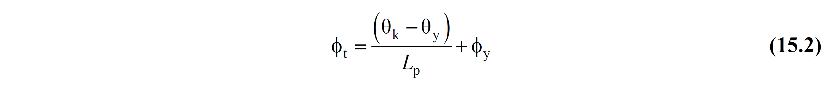
In this graph, the yield moment M y and the curvature at this point are defined as the yield curvature ϕ y . This point is the point where the reinforcements that receive tensile force according to the moment direction reach the yield stress. This value is the ϕ y value specified in Equation (15.2) described in TBDY Section 15.5.4.2 .
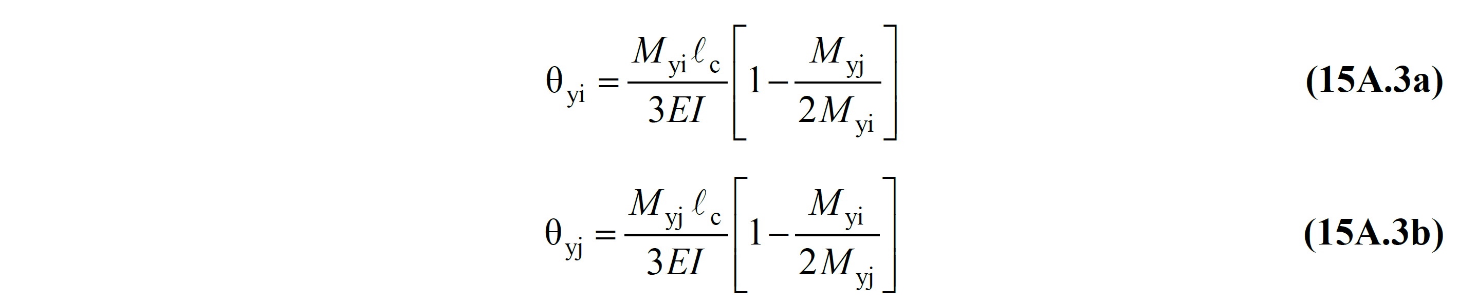
TBDY The values of M yi and M yj used in the equation in Equation (15A.3) and explained in Section 15A.3 are the torque values found as a result of the moment curvature analysis at the i and j ends of the element.
Next Topic
Related Topics