
How does ideCAD design Welded Web (WUF-W) Connections according to AISC 358-16 & AISC 360-16?
-
Design limit states of welded web connections are calculated automatically according to AISC 358-16 and AISC 360-16.
Symbols
Lh = distance between plastic hinge locations, in. (mm)
Lst = length of stiffener, as shown in Figure 6.5, in. (mm)
Mpr = probable maximum moment at the plastic hinge, kip-in. (N-mm), given by Equation 2.4-1
Sh = distance from the face of the column to the plastic hinge, in. (mm)
Vgravity = beam shear force resulting from 1.2D + f1L + 0.2S (where f1 is a load factor determined by the applicable building code for live loads, but not less than 0.5), kips (N)
Vu = shear force at the end of the beam, kips (N)
bbf = width of beam flange, in. (mm)
d = depth of connecting beam, in. (mm)
tp = thickness of end-plate, in. (mm)
S1 = distance from face of column to nearest row of bolts, in. (mm)
Ze = Effective plastic modulus of section (or connection) at the location of a plastic hinge, in.3 (mm3)
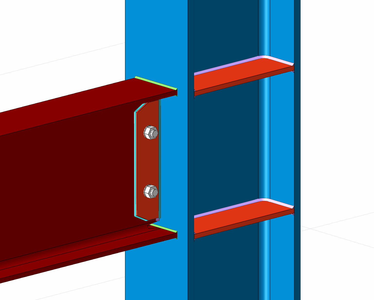
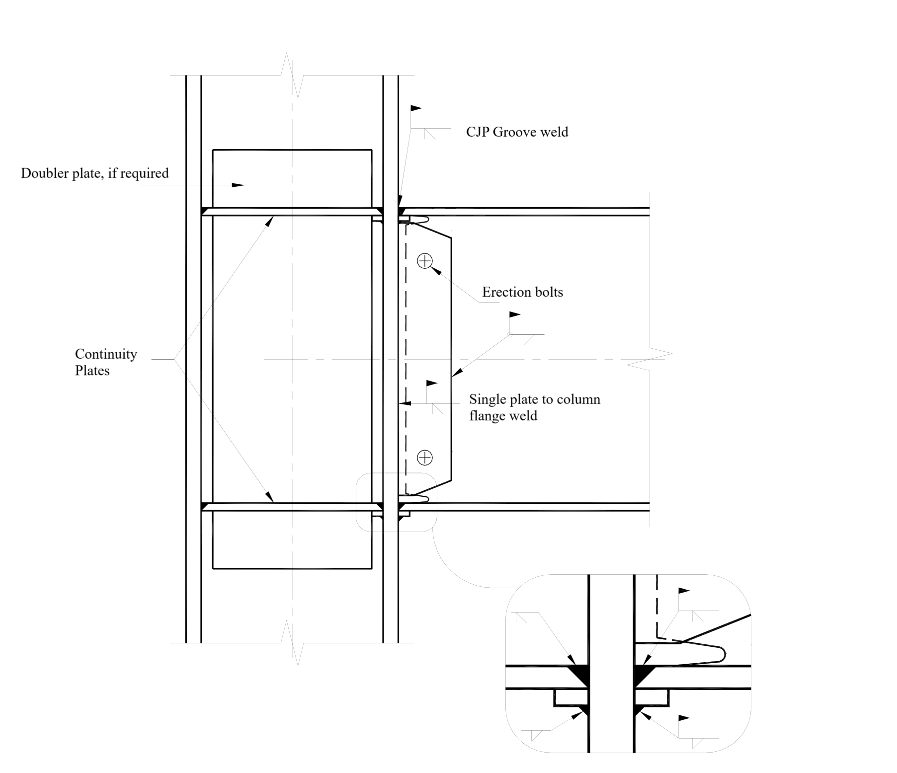
Welded web moment connections consist of welds joining the beam flanges to the column
flange, and the welds joining the beam web to the column flange. Welded Web (WUF-W) Connections are prequalified for use in seismic effects within the limits of these provisions.
Connection Design Parameters
Resistance factor for ductile limit state (Yielding Limit State):
Resistance factor for Non-ductile limit state (Rupture Limit State):
Distance from the face of the column to the plastic hinge, Sh, for bolted flange plate moment connections, is calculated by using the equation given below according to AISC 358-16 Eq. 7.6-5.
PREQUALIFICATION LIMITS
Beam Limitations
-
Beam depth is limited to a maximum of 36 in. (920 mm) for rolled shapes. The depth of built-up sections does not exceed the depth permitted for rolled wide-flange shapes.
-
Beam flange thickness is limited to a maximum of 1 in. (25 mm).
-
The clear span-to-depth ratio of the beam is limited as follows:
-
For special moment frame systems, 9 or greater.
-
For intermediate moment frame systems, 7 or greater.
-
-
The protected zone consists of the portion of the beam between the face of the column and a distance of one beam depth, d, from the face of the column.
Column Limitations
-
The beam is connected to the flange of the column.
-
Rolled-shape column depth is limited to a maximum of 36 in. (920 mm) when a concrete structural slab is provided. In the absence of a concrete structural slab, the rolled-shape column depth is limited to a maximum of 14 in. (360 mm).
Flanged cruciform columns don’t have a width or depth greater than the depth allowed for rolled shapes. Built-up box columns don’t have a width or depth exceeding 24 in. (600 mm). Boxed wide-flange columns don’t have a width or depth exceeding 24 in. (600 mm) if participating in orthogonal moment frames.
The probable maximum moment at the plastic hinge is given below, according to AISC 358-16.
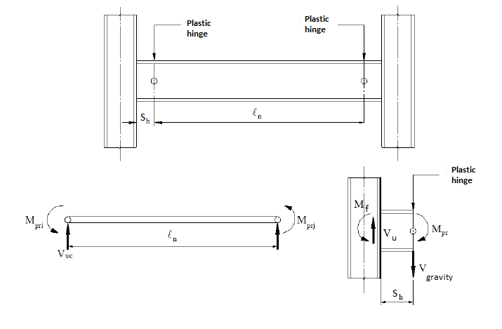
The value of Ze shall be taken as equal to Zx of the beam section, and the value of Cpr is taken as equal to 1.4.
The moment at the face of the column, Mf., is calculated according to AISC 358-16 Eq. 6.8-1 given below.
The Vu used in the dimensioning of the joint is determined according to the equation in the above image by summing the shear force determined based on the yield state and the shear force calculated from the combination of 1.2G + 0.5Q + 0.2S on the plastic joint at the end of the beam.