
-
Modal Pseudo-Acceleration and Modal Displacements are calculated automatically.
ICONS
a 1 (X,k) = modal pseudo-acceleration [m/s2] of the first mode modal single degree of freedom system at the kth push step for earthquake direction [m/s2]
d 1 (X,k) = (X) earthquake modal displacement of the modal single degree of freedom system belonging to the first mode in the kth thrust step for the kth thrust for the earthquake direction[m]
m i = the total mass of the i th floor
m ix1 (X,1) = (X) the first thrust in the x-axis direction for the earthquake directionith floor modal effective mass [t]
m tx1 (X,1) calculated accordingto the constant mode shape determined in step and never changed during the thrust calculation
= (X) modal effective mass of the base shear force calculated according to the constant mode shape determined in the first thrust step in the x-axis direction for the earthquake direction and never changed during the thrust calculation [t]
m iy1 (X,1) = (X) for the earthquake direction i'th floor modal effective mass calculated according to the constant mode shape determined in the first thrust step in the y-axis direction and never changed during the thrust calculation [t]
m iθ1 (X,1) = (X) for the earthquake direction in the first thrust step around the z-axis The ith floor calculated according to the fixed mode shape determined and never changed during the thrust calculation
modal effective mass moment of inertia [tm2]
u ix1 (X,k) = (X) displacement calculated in the x-axis direction at the ith floor at the kth thrust step for the earthquake direction [m]
u Nx1 (X,k) = (X) k earthquake directions lactide pushing step in the Nth floor (top of the building) the displacement, calculated according to the axis X [m]
V TX1 (X, k) = (X) k earthquake directions' th, calculated according to the x-axis in step push base shear [kN]
Δa 1 (X,k) = modal pseudo-acceleration increment of the first mode modal single degree -of- freedom system at the kth push step for the earthquake direction (X)[m / s 2 ]
Δd1 (X, k) = (X) k earthquake direction of the 'th pushing step the first mode of modal single degree of freedom system ' s modal displacement of [m]
Δf ix1 (X, k) = (X ) k earthquake direction of the 'th thrust step i' th floor, the x-direction acting seismic load increment [kN]
Δf iy1 (X, k) = (X) k earthquake direction of the 'th thrust step i' th floor acting along the Y axis earthquake load increment [kN]
Δf iθ1 (X,k) = (X) earthquake load increase acting in the z axis direction at the i th floor at the k th thrust step for the earthquake direction [kN]
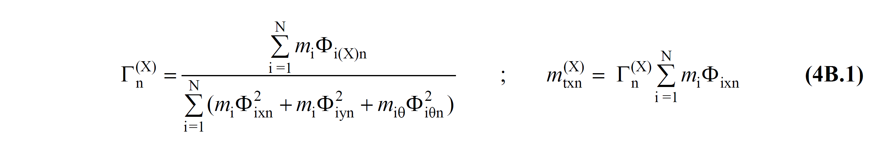
Γ 1 (X,1) = (X) determined in the first thrust step for the earthquake direction and never changed during the thrust calculation modal contribution factor calculated according to fixed mode shape
TDY Equation 5B.1 from the Δ located one (X, k) two successive hinge formation defined between the k 'th thrust unknown size in step second order effects the consideration to be the initial step in the modal analysis of the first mode (the dominant mode) of the modal single degree of freedom system 's Modal so-called Growth Acceleration is.

The modal pseudo-acceleration increment is calculated from the yield condition defined in TDY 5.3.1 of a new plastic hinge formed at the end of each step . This value also determines the iteration level of the impulse analysis . The resulting modal pseudo acceleration increment, Δa 1 (X,k) , is added to the pseudo acceleration value found at the end of the previous step to obtain the cumulative modal pseudo acceleration a 1 (X,k) at the kth step . In your cumulative modal, acceleration a 1 (X,k) value can be written as given in TDY Equation 5B.3 .

In this equation, in the kth step (X) of the thrust analysis, the base shear force in the earthquake direction is expressed as V tx1 (X,k) , and the base shear force is expressed as modal effective mass m tx1 (X,1) .
m tx1 (X,1) is the modal effective mass obtained in the first mode of the modal analysis , the value of which is taken into account in the initial step where second-order effects are taken into account, and it is found by TDY Equation 4B.1 . The value of m tx1 (X,1) is calculated only for the first step and is the sum of the floor modal effective masses m tx1 (X,1) values taken as constant throughout the entire thrust calculation .
For the earthquake direction ( X ) given in TDY Equation 5B.3 , the base shear force V tx1 (X,k) calculated in the kth step of the thrust analysis is calculated cumulatively for each thrust step. Therefore, the so-called modal acceleration a 1 (X,k) is obtained cumulatively. In this case, the modal pseudo-acceleration increment, Δa 1 (X,k) , can also be calculated from the base shear forces that change at each thrust step.
As a result of the modal analysis performed in the initial step , TDY Equation 5B.4 is used to calculate the modal displacement d 1 (X,k) of the system with one degree of freedom belonging to the first mode .

In this equation, the Nx1 (X, k) , (X) of the push analyzed for earthquake directions k 'th calculated in step N' peak displacement of the fifth floor 'of the latter. Φ Nx1 (1) is the mode amplitude at the Nth floor obtained in the first mode of the modal analysis performed in the initial step . The values in the denominator of TDY Equation 5B.4 are the values obtained in the first mode of the modal analysis performed in the initial step, where second-order effects are taken into account, and these values are used in all push steps.
With the value of u Nx1 (X,k) and V tx1 (X,k) , a thrust curve whose coordinates are base shear force-peak displacement is obtained. To find the performance point, the V tx1 (X,k) term TDY Equation 5B.3 and the u Nx1 (X,k) term TDY Equation 5B.4 are applied.