
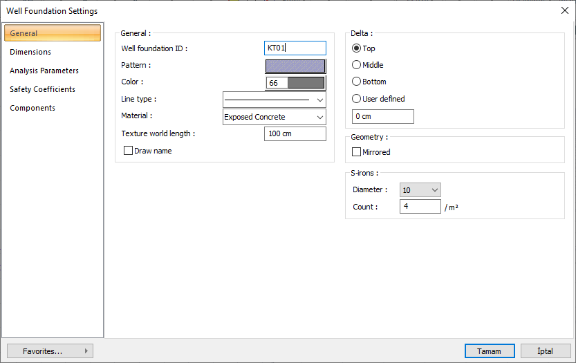
With the Well Basic Settings command, settings such as dimensions, crosstie, drawing, material selection, structural material can be accessed.
Location of Well Foundation Settings Dialog
Toolbar that appears after the well foundation command is run is also available in the auxiliary toolbar.
General Tab
|
Specifications |
|---|
|
Well foundation ID Well is the name of the well foundation that will appear in the meter and report. |
|
Pattern It is the hatching type of well foundation. When the scan box is clicked, the appropriate hatch type is selected from the window that opens. |
|
Color Well is the color of the foundation visible in the plan and in the 3-dimensional model. When the color box is clicked, the appropriate color is selected from the window that opens. |
|
Line type When clicked, the line type of the line that appears in the well base plan is selected from the drop-down list. |
|
Material Select element texture for use in solid model. If the texture is not selected, the well foundation's own color is used in the solid model. |
|
Texture world length Texture length is entered. For example; If the length is entered as 1 meter, the selected material texture is taken as 1 meter and covered on the selected object. If the texture is considered to be in the form of a square, the object surfaces are covered with 1x1 textures arranged side by side. |
|
Draw name If the option is checked, it will appear on the well foundation ID on the plan screen. |
|
Delta 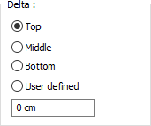
These are the options that determine from where the well foundation will be defined. If the virtual axis joining the joints at the two ends of the well foundation is to coincide with the upper edge of the foundation according to the direction of view, top, bottom edge if the well will coincide with the lower edge and middle option if it will pass through the middle option is marked. If the virtual foundation axis will pass through another line, user defined option is checked and the distance to the upper edge of the well foundation is entered in the lower data entry box. |
|
S-irons 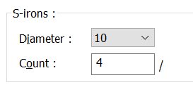
The well basically determines the diameter and number of crossties to be used. |
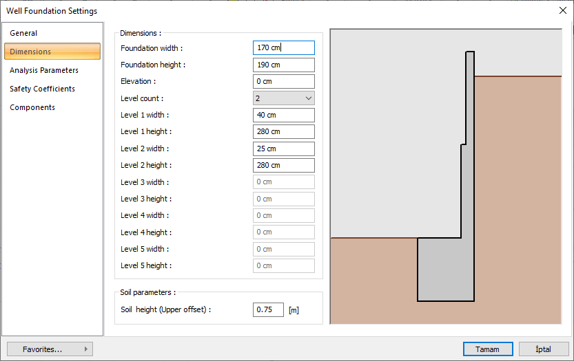
Dimensions Tab
|
Specifications |
|---|
|
Foundation width The width of the well foundation is entered. |
|
Foundation height The height of the well foundation is entered. |
|
Elevation Give the base level of the well foundation. With a value of zero, the well foundation is at the zero point in the z-axis in the global coordinate system. |
|
Level count Give the count of level on the well foundation. Organize the width information at the bottom according to the number you will give. |
|
Level sizes 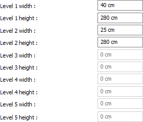
The height and width values of each level are entered. |
|
Soil height Fill (ground height) remaining on the soil side of the well foundation is given. You can watch the entered value as shown on the right. |
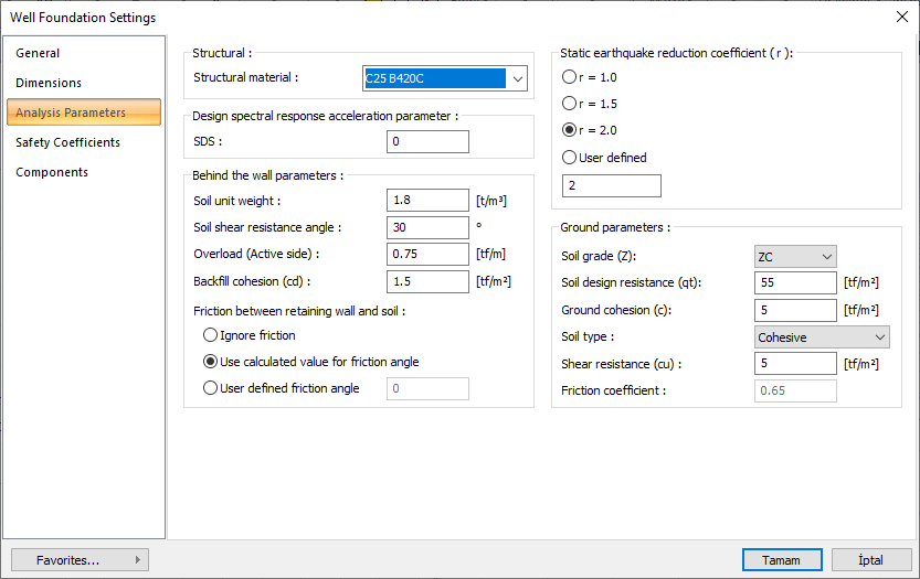
Analysis Parameters Tab
|
Specifications |
|---|
|
Structural material 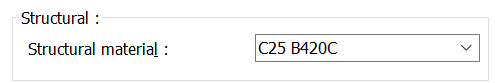
Select the reinforced concrete material to be used in the calculation and reinforced concrete of the retaining wall from the list. |
|
Design spectral response acceleration parameter 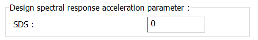
TBDY 2018 according stipulated for retaining walls SDS enter the value. |
|
Static-eqarthquake reduction coefficient 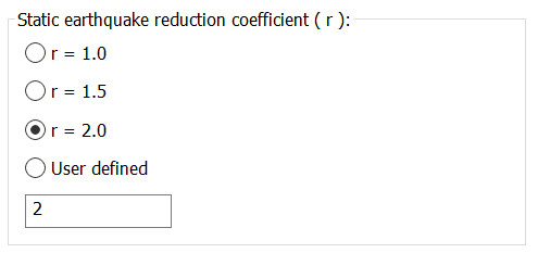
According to TBDY 2018 Table 16.7, the r coefficient to be used in the calculation of soil pressures is selected. 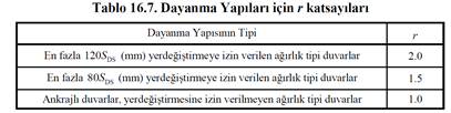
|
|
Soil unit weight
Enter the unit weight of the floor to be used as backfill. |
|
Soil shear resistance angle Enter the slip resistance angle value according to the type of backfill ground. |
|
Overload (Active side) If available, enter the overload value on the active side. |
|
Backfill cohesion (cd) Enter the cohesion value of the backfill soil. |
|
Friction between retaining wall and soil 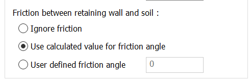
You can ignore friction, use the calculated friction value, or enter your own calculated friction angle value. |
|
Soil grade You can select the floor class determined according to TBDY 2018 from the list. |
|
Soil design resistance (qt) The basic bearing capacity for TBDY 2018 is the design strength (qt). It is determined according to the ground report. The basic load bearing design strength qt is the ratio of the soil characteristic strength qk to the strength coefficient value of 1.4. (TBDY 2018 Article 16.8.2) |
|
Ground cohesion (c) Enter the cohesion value of the soil. |
|
Soil typle The determined floor type is selected from the list |
|
Shear resistance (cu) The undrained shear strength value determined in cohesive soils is entered. |
|
Friction coefficient Give the coefficient of friction of the ground according to the soil type. |
Safety Coefficients Tab
|
Specifications |
|---|
|
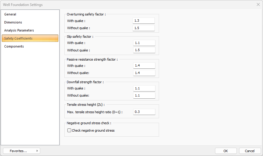
Overturning safety factor 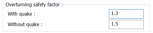
The coefficients to be used in the rollover safety calculations are determined from the relevant boxes for earthquake and non-earthquake situations. |
|
Slip safety factor 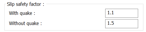
The coefficients to be used in slip safety calculations are determined from the relevant boxes for earthquake and non-seismic situations. |
|
Passive resistance strength factor 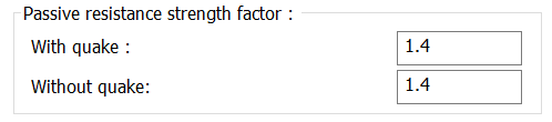
The coefficients to be used in passive resistance endurance safety calculations are determined from the relevant boxes for earthquake and non-earthquake situations. |
|
Downfall strength factor 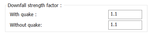
The coefficients to be used in wholesale failure safety calculations are determined from the relevant boxes for earthquake and non-seismic situations. |
|
Tensile stress height 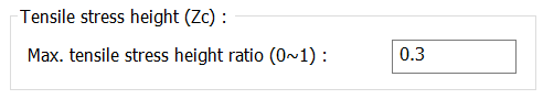
The maximum value of the crack tension crack, which is expected to occur downwards from the upper level of the soil in clayey soils, is determined here. |
|
Tensile stress height 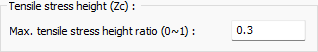
The maximum value of the tensile stress height ratio that is expected to occur from the top soil level down in clayey soils is determined here. |
|
Negative ground stress check 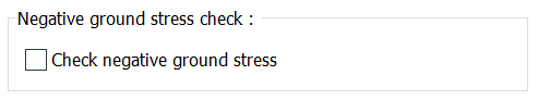
Negative ground stresses may occur as a result of the well foundation analysis. If this option is checked, the program will give a negative message as a result of the calculation if negative stress has occurred in the foundation. |
Components Tab
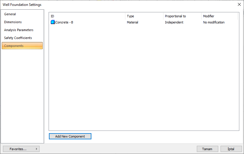
Add Building Components: Assigns the building materials defined for detailed building components metrics to the object.
-
Click on the building components button.
-
The Component Selection dialog will open.
-
In this dialog, click on the folder related to the material from the list on the left. Click on the material you want to use.
-
Set the parameters on the right.
-
Click the OK button. The "Component Selection" dialog will be closed. A summary line of the material will appear in the Building Components tab. More than one material assignment can be made to an object.
The parameters available in the Component Selection dialog are:
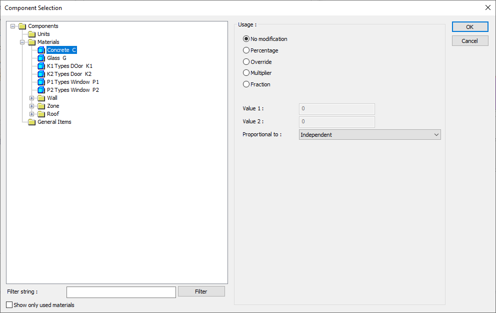
In the usage section
No modification: The amount of material to be assigned for the object in question is marked when it is desired to be used in the size that was previously specified in the material definition.
Percentage: This line is marked when it is desired to be used with the percentage of the amount previously determined in the material definition, as much as the value entered in the "Value 1" line in the same dialog. For example, if the material quantity is 70, if the line “Value 1” says 40, it means the material amount will be used up to 40 * 70%.
Override: This line is marked so that the quantity entered in the “Value 1” line in the same dialog will be used instead of the quantity previously determined in the material definition.
Multiplier: This line is marked in order to use the value found at the end of the multiplication of the value entered in the "Value 1" line in the same dialog with the amount previously determined in the material definition.
Fraction: This line is marked so that the amount determined in the material definition before will be used as the fraction value created by the values entered in the "Value 1" and "Value 2" lines in the same dialog. "Value 1" is the denominator "Value 2" is the denominator.
Proportional to: It is determined to what scale-area, circumference, length etc.-, region-side area, top, edge etc.- the material will be proportioned to. The content of the proportional list box is automatically determined according to the object and the size of the material. For example, a different list will be created if an operation is made for the column, a different list will be created for the library, a different list for the volume, and a different list for the field.
The lines that appear in the Proportion list according to the well base object and material size are as follows:
|
Well Foundation |
||
|
Measure |
Listed |
Explanation |
|
Constant |
Independent |
The fixed measure used will be used exactly as the amount. |
|
Length |
Independent |
It means that the length measure found while defining the material will be used exactly as the length value. |
|
Area |
Independent |
The area measure found when defining the material will be used exactly as the area of the material. |
|
Volume
|
Independent |
The volume measure found when defining the material will be used exactly as the volume of the material. |
|
Volume |
The volume measure found when defining the material will be used exactly as the volume of the material. |
|
|
Count |
Independent |
The count measure found while defining the material will be used exactly as the material count. |
Next Topic