
How does ideCAD design Welded Web (WUF-W) Moment Connections according to AISC 358-16 & AISC 360-16?
Design limit states of welded web connections are calculated automatically according to AISC 358-16 and AISC 360-16.
Symbols
Ag: Gross area
An: Net cross-section area
Ae: Effective net cross-sectional area
Avg: Gross area under shear stress
Anv: Net area under shear stress
Ant: Net area under tensile stress
Aw: Cross-section web area
bbf = width of beam flange, in. (mm)
bp = width of end-plate, in. (mm)
d = depth of connecting beam, in. (mm)
g = horizontal distance between bolts, in. (mm)
dh: Bolt hole diameter
Fy: Structural steel characteristic yield strength
Fu: Structural steel characteristic tensile strength
nsp: Number of slip planes
K: Effective length factor
L: Connector distance
tbf = thickness of beam flange, in. (mm)
tp = thickness of end-plate, in. (mm)
w = Size of weld leg, in. (mm)
Rn: Characteristic strength
Rnwl: Total nominal strength of longitudinally loaded fillet welds
Rnwt: Total nominal strength of transversely loaded fillet welds,
Connection Geometry
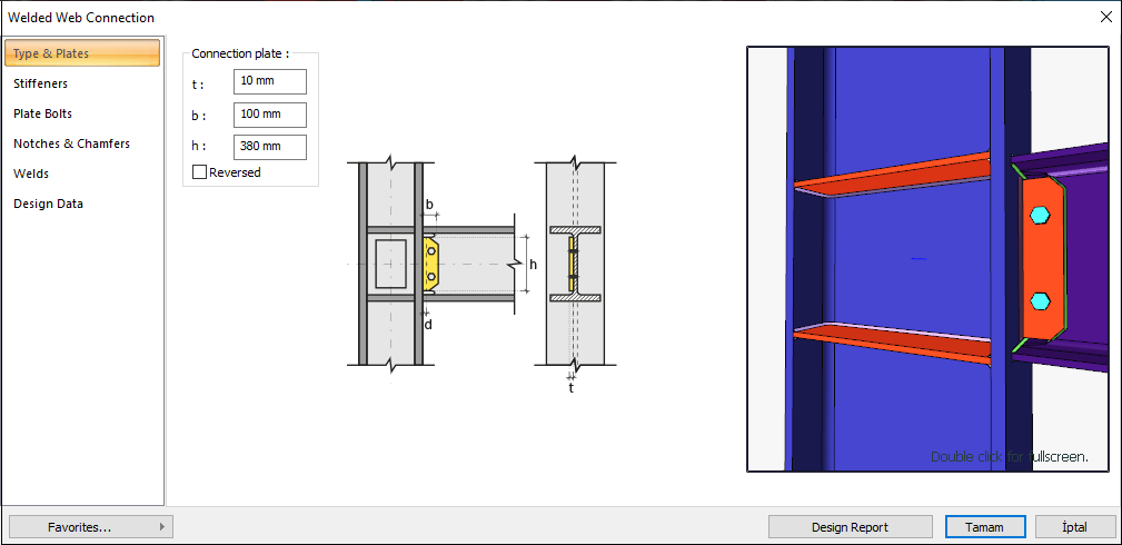
GEOMETRY CHECKS
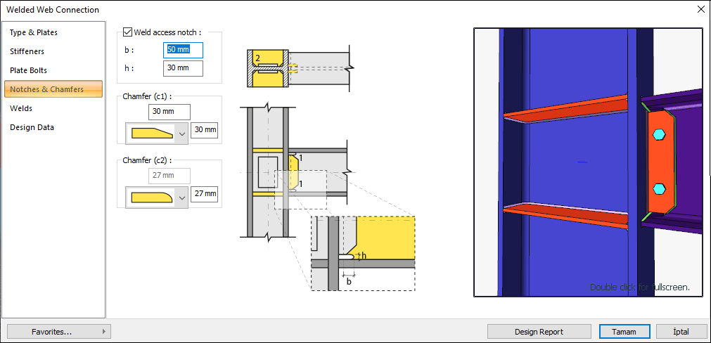
Weld Access Hole Length
The maximum weld access hole length is checked per AISC 360-16.
|
L ≥ max( 1.5tw, 38 mm ) |
AISC 360-16 J1.7 |
|
|
L |
50 mm |
√ |
|
tw |
9 mm |
√ |
Weld Access Hole Height
The maximum weld access hole height is checked per AISC 360-16.
|
H ≥ max( tw, 19 mm ) , H≤50mm |
AISC 360-16 J1.6 |
|
|
H |
30 mm |
√ |
|
tw |
9 mm |
√ |
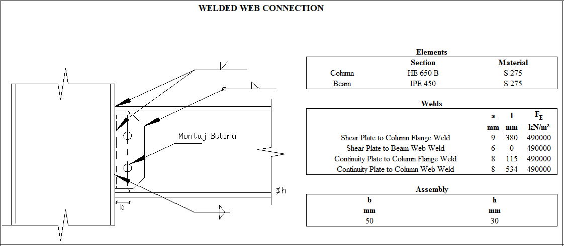
Shear Plate to Column Flange Weld Size
The minimum size of fillet welds is checked according to AISC 360-16 Table J2.4
|
w≥ wmin |
|
|
|
|
w |
12.73 mm |
|
√ |
|
wmin |
5 mm |
AISC 360-16 Table J2.4 |
√ |
Shear Plate to Beam Web Weld Size
The minimum size of fillet welds is checked according to AISC 360-16 Table J2.4
|
w≥ wmin |
|
|
|
|
w |
8.487 mm |
|
√ |
|
wmin |
5 mm |
AISC 360-16 Table J2.4 |
√ |
Continuity Plate to Column Flange Weld Size
The minimum size of fillet welds is checked according to AISC 360-16 Table J2.4
|
w≥ wmin |
|
|
|
|
w |
11.315 mm |
|
√ |
|
wmin |
6 mm |
AISC 360-16 Table J2.4 |
√ |
Continuity Plate - Column Body Welding Thickness
The minimum size of fillet welds is checked according to AISC 360-16 Table J2.4
|
w≥ wmin |
|
|
|
|
w |
11.315 mm |
|
√ |
|
wmin |
6 mm |
AISC 360-16 Table J2.4 |
√ |
PREQUALIFICATION LIMITS
|
Beam span / Beam cross-section height |
9144 mm /450 mm=20.32 |
≥9.0 |
|
Beam cross-section |
450 mm |
≤ 920 |
|
Beam head thickness, tbf |
15 mm |
≤25 |
|
Column cross-section height |
650 mm |
≤ 920 mm |
|
Flange plate weld |
CJP |
CJP |
|
tp |
10 mm |
≥9 mm |
|
a |
10 mm |
6≤a≤12 |
|
d |
50 mm |
≥50 mm |
|
Shear plate beam web weld size |
6 mm |
=6 mm |
|
Flange plate weld |
CJP |
CJP |
STRENGTH CHECKS
Beam Shear Yield
The nominal and design yield strength of the web plate is checked according to AISC 360-16
|
Ag |
|
|
|
Fy |
275 N/mm2 |
|
|
Rn |
|
AISC 360-16 J4-3 |
|
ΦRn |
|
|
|
Required |
Available |
Ratio |
Control |
|---|---|---|---|
|
265.569 kN |
534.6 kN |
0.497 |
√ |
Shear Plate to Column Flange Weld Strength
The nominal and design weld strength for the shear plate to column weld is checked according to AISC 360-16
|
Fe |
490000 kN/m2 |
AISC 360-16 J2-3 |
|
w |
12.73 mm |
|
|
l |
380 mm |
|
|
Rreq |
|
|
|
hp |
380 mm |
|
|
tp |
10 mm |
|
|
Ry |
1.30 |
|
|
Fyp |
275 N/mm2 |
|
|
Rn |
|
|
|
ΦRn |
|
|
|
Required |
Available |
Ratio |
Control |
|---|---|---|---|
|
815.1 kN |
904.94 kN |
0.901 |
√ |
Column Panel Zone Shear
The welded web connection's panel zone shear limit state is checked according to AISC 360-16.
|
Pr |
429.124 kN |
AISC 360-16 J10-9 |
|
Py |
|
|
|
F y |
275000 kN/m2 |
|
|
A g |
28634.759 mm2 |
|
|
dc |
650 mm |
|
|
tw |
16 mm |
|
|
Rn |
|
|
|
ΦRn |
|
|
|
Required |
Available |
Ratio |
Control |
|---|---|---|---|
|
1497.795 kN |
1716 kN |
0.873 |
√ |
Panel Zone Thickness
The required panel zone thickness for welded web connection is checked according to AISC 358-16.
|
tmin ≥u / 180 |
|
|
tmin = tw |
16 mm |
|
tw |
16 mm |
|
u |
2016 mm |
|
Required |
Available |
Ratio |
Control |
|---|---|---|---|
|
11.2 mm |
16 mm |
0.700 |
√ |