
-
Longitudinal reinforcement conditions in columns are automatically controlled and the reinforcement arrangement is done automatically.
-
The condition that longitudinal reinforcement area in columns will not be less than 1% and greater than 4% of the gross section is automatically controlled and applied.
-
The condition is not to use reinforcement less than dairesel14 in columns and less than 6 in circular columns.
-
The condition that the total longitudinal reinforcement ratio will not exceed 6% is applied automatically in the sections with lap joints.
ICONS
A c = Gross cross-sectional area of the column
A s = Longitudinal reinforcement area of the column
ϕ = Reinforcement diameter
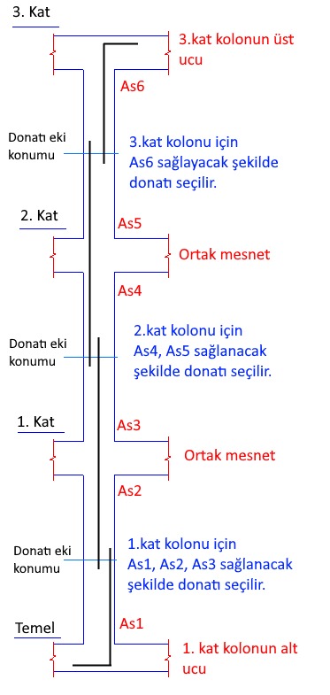
Calculation effects (M xd , M yd , N d ) used in the column reinforcement calculation are found from the combination of earthquake, vertical, wind and soil loads, if any. For each loading, column reinforcement calculation is made at the top node of the column in the same floor and at the bottom node of an upper floor. In terms of the joint support of the existing floor and the upper floor, the largest area of reinforcement found from each combination is the reinforcement amount of that floor column. The same process is applied in all layers.
The selection of reinforcement is shown schematically. A s1 , A s2 , A s3 , A s4 and A s6 represent the largest reinforcement areas found from each combination at the top and bottom joints of the column.
Taking into account 7.3.2.1 , the area of column longitudinal reinforcement is not allowed to be less than 1% of the gross section.
The condition of not exceeding 6% of the total longitudinal reinforcement specified in item 7.3.2.2 'shall be taken as half of the value (3%) for each column itself, and a control is made to be 6% in total. When the longitudinal reinforcement ratio is exceeded by 3%, it is requested to increase the column dimensions.
For each column:
As >= 0.01 Ac
As <= 0.03 Ac
In the columns thinner than ϕ14 and in circular columns less than 6 bars are not used.
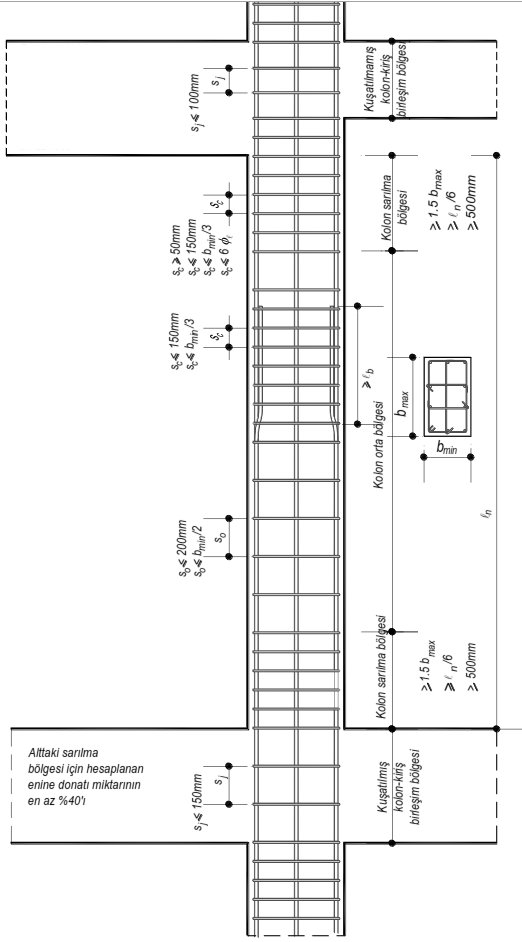
Column splices are made in the middle of the column with relatively less strain.
The principles taken into account in the detail drawings for column longitudinal reinforcements:
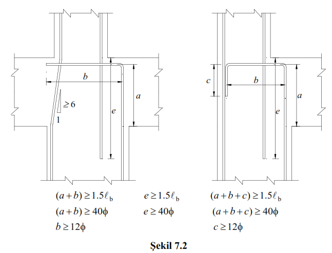
The conditions given in (TBDY, Figure 7.2) are applied while preparing the details of the reinforcements that cannot be interlocked in the upper storey column due to the change in the column cross section from floor to floor .
Next Topic