
Symbols
Ag : Gross cross-sectional area of member
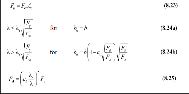
Ae : Effective area
c1, c2 : Effective width imperfection adjustment factor determined from Table 8.2
Fcr : Critical stress
Fe : Elastic buckling stress
Fe1 : Elastic buckling stress determined according to Equation 8.25,
Fy : Specified minimum yield stress of the type of steel being used,
K : Effective length factor
L: Laterally unbraced length of the member
Lc : Effective length of the member, (= KL)
i: Radius of gyration
λ: Width-to-thickness ratio for the element
λr : Limiting the width-to-thickness ratio as defined in Table 5.1a
Flexural Buckling Limit State
-
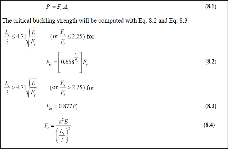
The limit state of flexural buckling is applicable for axially loaded columns with, doubly symmetric sections such as bars, circular and square HSS, I-shapes, and single symmetric sections, such as T- and U-shapes. Flexural buckling is the simplest type of buckling.

Design with ÇYTHYE 2018
-
The compressive strength of the elements is determined according to the axial force acting into the center of gravity section. According to the regulation, the bending buckling limit state is taken into account in all compression elements, regardless of cross-section properties. The equations used for this are given below in order.
-
First of all, local buckling control should be done. The calculation is performed according to whether the elements are compact or non-compact.
Flexural Buckling Members Non-Slender Elements
Flexural Buckling Members with Slender Elements
Next Topic