
-
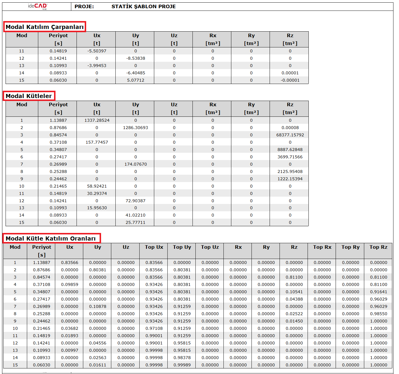
Modal Effective masses are automatically calculated and reported for each mode.
-
Modal Mass Participation Rates are automatically calculated and reported for each mode.
-
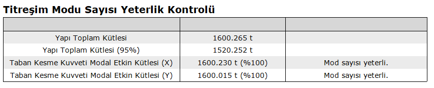
According to TBDY 4.8.1.2 (a) , the sum of the base shear force modal effective masses calculated for each mode in the (X) and (Y) earthquake directions should not be less than 95% of the total building mass , the control is automatically performed and reported.
-
Targeted Modal Mass Participation Rate value is under user control. Taking this value into consideration TBDY 4.8.1.2 (a) , the default value of 0.95 was entered.
ICONS
m i = total mass of the i th floor
m iθ = mass moment of inertia of the i th floor
m ixn (X) = (X) the i'th floor modal effective mass m of the nth natural vibration mode of the building in the x-axis direction for the earthquake direction iyn (X) = (X) earthquake direction, i'th floor modal effective mass belonging to the nth natural vibration mode of the building in the y-axis direction
m iθn (X) = (X) the nth natural vibration of the building around the z-axis for the earthquake directionth floor modal effective mass moment of inertia
m j (S) = Single mass acting at typical finite element node j
m t = Total mass of the upper section of the building above the basement floors
m txn (X) = Base shear force of the nth vibration mode of the building in the x-axis direction for the earthquake direction (X) modal effective mass
m tyn (Y) = (Y) base shear force modal effective mass of the building in the y-axis direction for earthquake direction
YM = Number of sufficient vibration modes
β mn = ratio of m and nth natural vibration periods
Φ i(X) n = nth natural vibration mode shape amplitude in the earthquake direction at i'th floor (X)
Φ ixn = nth natural vibration mode shape amplitude in the x-axis direction at i'th floor
Φ iyn = nth natural vibration mode shape amplitude in the y-axis direction at i'th floor vibration mode shape amplitude
Φ iθn = nth natural vibration mode shape amplitude as rotation around z axis at i'th floor
Γ n (X) = (X) modal contribution factor of nth vibration mode for earthquake direction
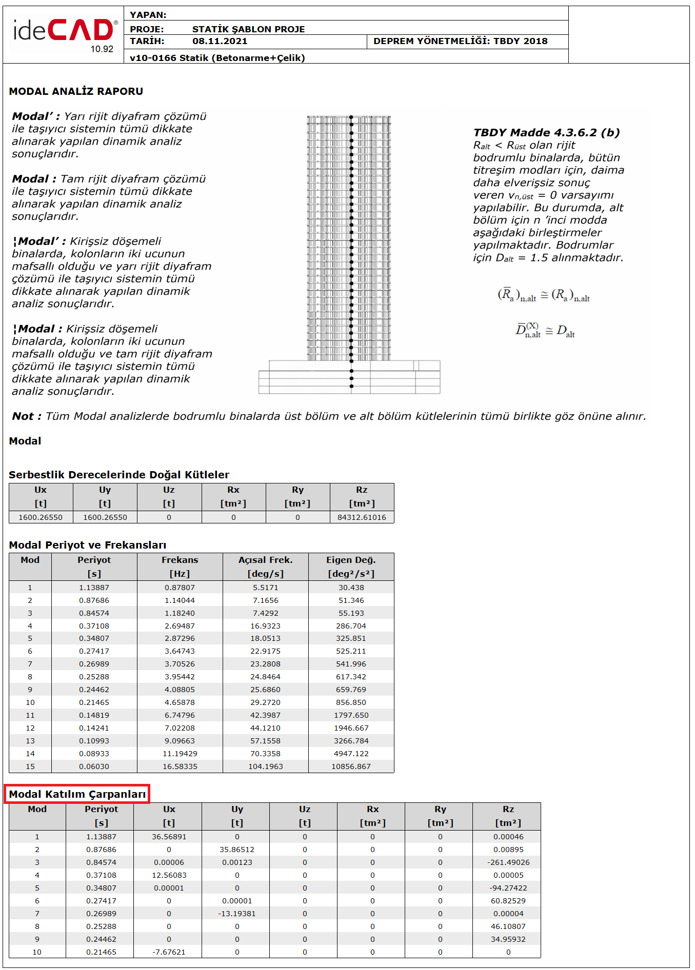
Modal calculation parameters are defined below only for (X) horizontal earthquake direction. The same parameters can be defined similarly for the earthquake direction (Y) perpendicular to (X).
The Stories Modal Effective Masses specified in TBDY 4B.1.5 are defined as follows, with the floor modal effective masses belonging to the degrees of freedom defined in 4B.1.3 above, in a typical n'th vibration mode for the given earthquake direction (X) .
In case the floor slabs are modeled as rigid diaphragms according to TBDY 4B.1.3(a) , the displacements defined in the x and y horizontal directions at the center of mass of any ith floor slab and the rotation around the vertical axis passing through the floor mass center are taken into account and the corresponding degrees of freedom are taken into account. The storey mass mi is defined by the storey mass moment of inertia miθ . In case floor slabs are not taken as rigid diaphragms according to TBDY 4B.1.3(b) and are modeled with two-dimensional sheet (membrane) finite elements to include degrees of freedom for displacements in their planes according to TBDY 4.5.6.2 , m iInstead of storey masses, m j (s) masses at finite element nodes are taken into account.
All 6 degrees of freedom together with the (X) direction are used for modal analysis in three-dimensional systems. For this reason , (Y), (Z), (RX), (RY) and (RZ) values are also calculated and reported for the (X) terms defined in TBDY Equation 4B.2 .
The modal effective masses calculated above are the modal effective masses calculated for each mode. According to TBDY 4.8.1.2 , the sufficient number of vibration modes to be taken into account in the Mode Combination Method , YM , is determined according to TBDY Equation 4.30 . In this case , the sum of the modal effective masses must be more than 95 % of the total mass mt of the structure.
According to TBDY 4.8.1.2 (a) , the sum of the modal effective masses of the base shear force calculated for each mode in the (X) and (Y) earthquake directions should not be less than 95% of the total mass of the building .
However, all mods with a contribution greater than 3% will be considered. At the same time, the largest of the YMs calculated for both directions will be taken into account in the three-dimensional calculation.
As a result of the modal analysis made in ideCAD Static, the Modal Effective Masses and Modal Mass Participation Rates calculated for each mode can be examined in the Modal Analysis Report . Also in Modal Participation Factors Γ n ( X ) can be seen from the same report.
In the Modal Masses table , the calculated values of the modal mass values defined in TBDY Equation 4B.2 for all directions (UX), (UY), (UZ), (RX), (RY) and (RZ) are shown. Also , Modal Mass Participation Rates obtained by using Modal Masses are seen for each mode.
The mass participation rate specified in TBDY Equation 4.30 is seen in the Detailed Dynamic Analysis Report .
The Modal Mass Participation Ratios table shows the mass participation ratios in the (UX), (UY), (UZ), (RX), (RY) and (RZ) directions for each mode. In this table, the direction in which the mass participation of the relevant mode is high is accepted as the dominant direction for that mode. In this case, it can be interpreted for the above table that the 1st mode is dominant in the (UX) direction, the 2nd mode is dominant in the (UY) direction, and the 3rd mode is dominant in the (RZ) direction, in other words in the torsion direction.