
|
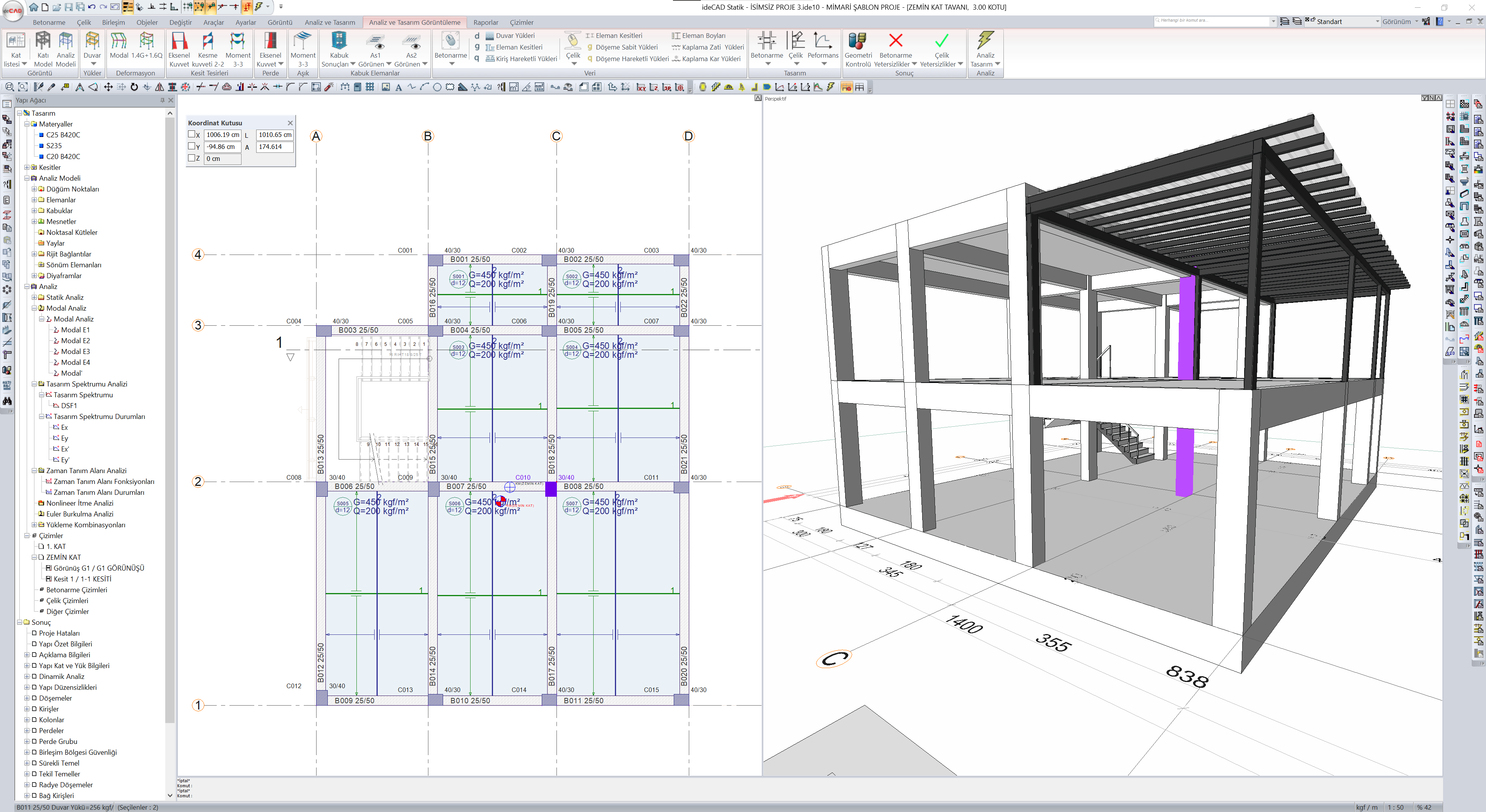
The project, which was prepared with ideCAD Architectural, was opened with ideCAD Structural. By making Analysis+Design, you can identify the failures with visualization possibilities and make the necessary intervention. |
-
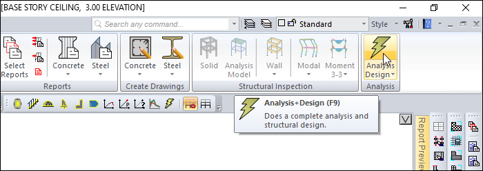
Click on the Analysis+Design (F9) command.
-
The Analysis Settings dialog will open.
-
Click the OK button to start the analysis.
-
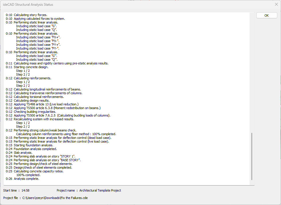
Wait for the analysis to complete in the Analysis Status window.
-
After the analysis is complete, click the OK button to close the window.

-
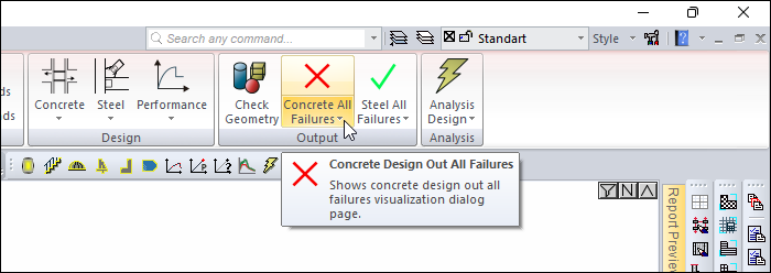
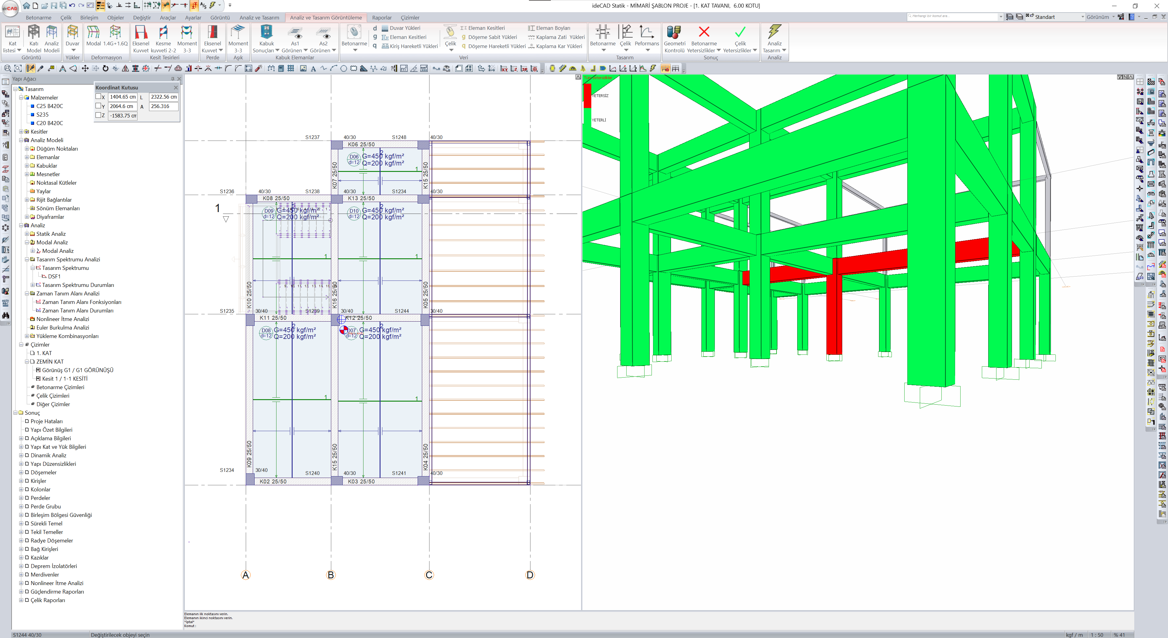
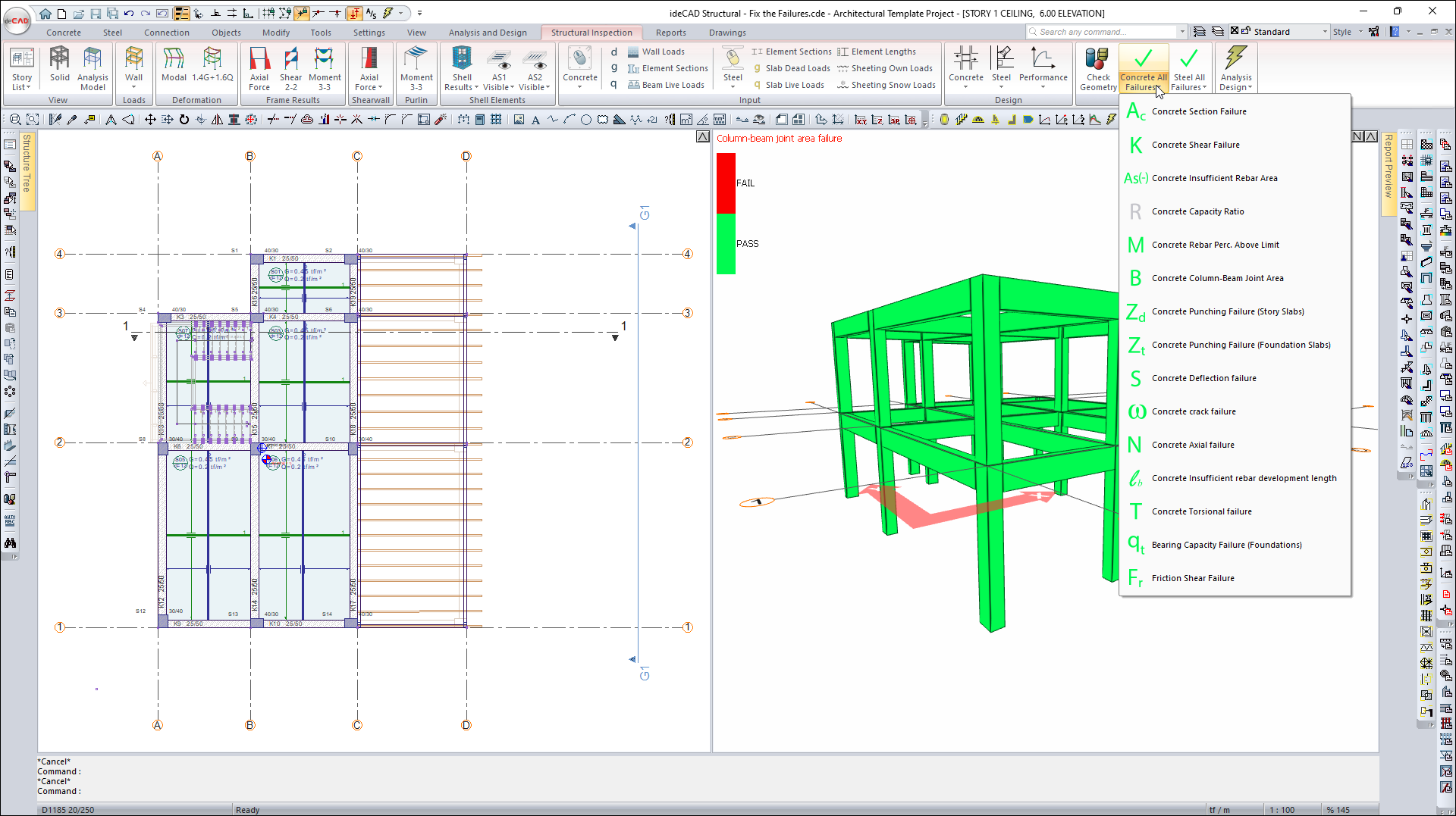
A red cross will be seen on the Output heading Concrete All Failures.
-
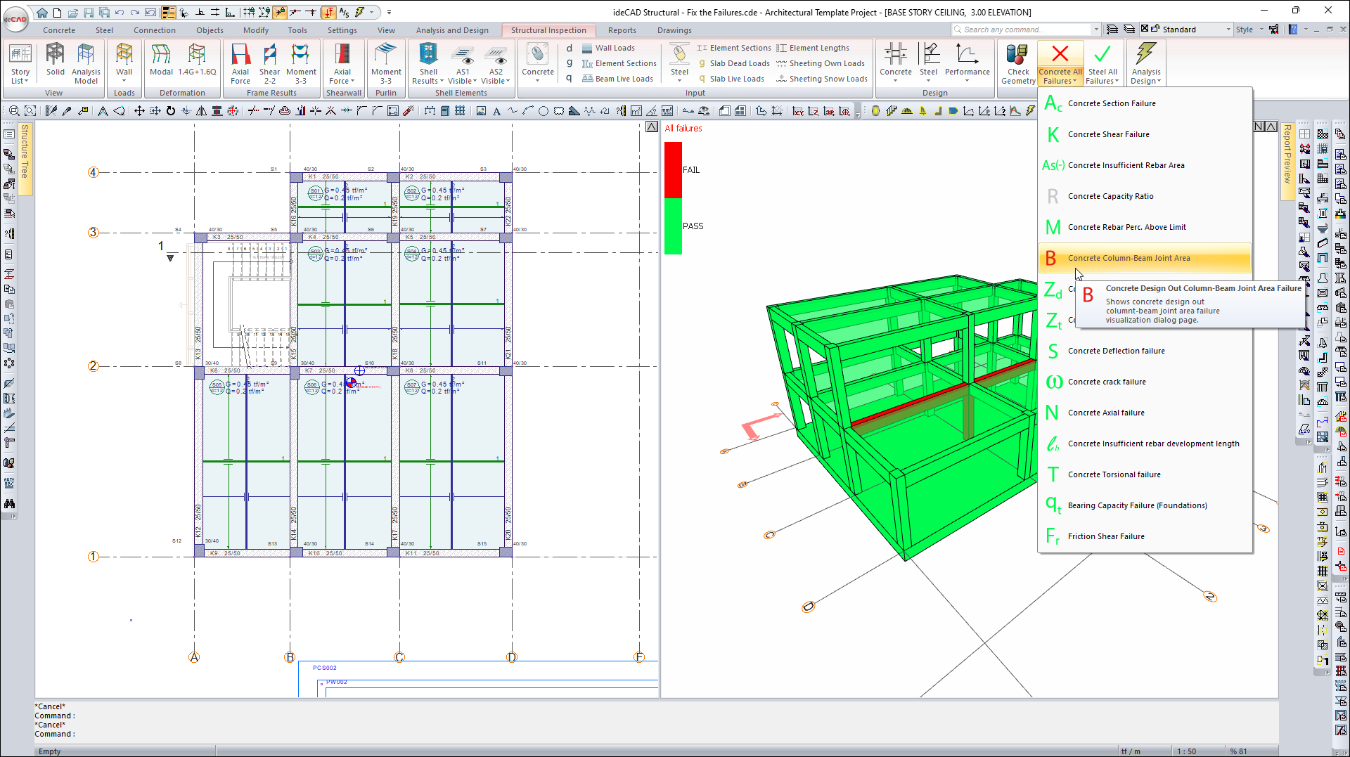
Open the Concrete All Failures list.
-
Click on the Concrete Column-Beam Joint Area.
-
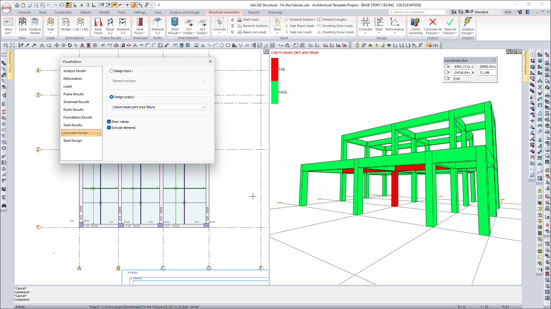
Elements with this failure appear in red in the Visualization Window.
-
Concrete Column-Beam Joint Area failure should be eliminated.
-
Close the visualization dialog.
-
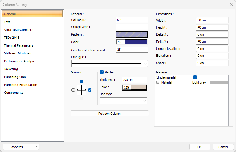
Open the Column Settings dialog by double-clicking on the S10 column.
-
In the General tab, write 30 cm for width value and 40 cm for height value.
-
Click the OK button to close the dialog.
-
Open the STORTY 1 CEILING page.
-
Open the Column Settings dialog by double-clicking on the S10 column.
-
In the General tab, write 30 cm for width value and 40 cm for height value.
-
Click the OK button to close the dialog.
-
Click the Analysis+Design (F9) command.
-
Do you want to perform analysis? question will be asked.
-
Click the Yes button.
-
Wait for the analysis to complete from the Analysis Status window.
-
After the analysis is complete, click the OK button to close the window.
-
A green tick will appear on Concrete All Failures in the Output heading.
-
This sign means that there is no failures in the project.
-
Open the Concrete All Failures list.
-
Click on the Concrete Column-Beam Joint Area failure.
-
Concrete elements will be displayed in green in the Visualization Window.
-
There is no Concrete Column-Beam Joint Area failure in the project.
Follow the steps of the video below.
Next Tutorial