
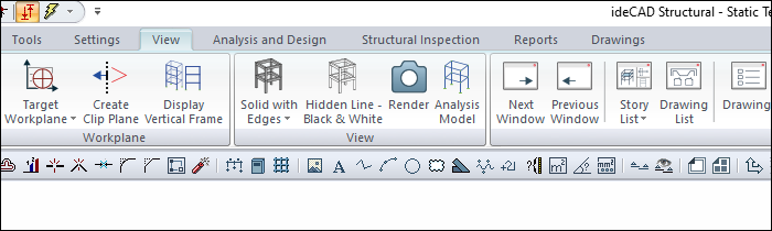
Any objects entered in the drawing area are simultaneously displayed in viewports (if viewed from the relevant viewpoint). It is possible to see the objects in these windows with Hidden Line , Black and White Hidden Line , Solid and Solid with Edges display techniques.
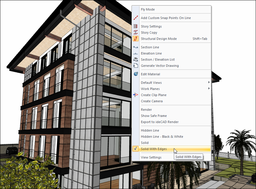
The same operations can be performed on the 3D view from the right-click menu.
To change the imaging technique;
-
Click the right mouse button on the corresponding viewport.
-
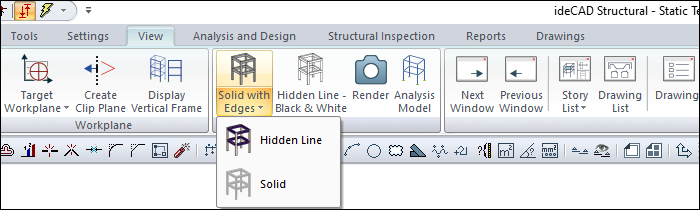
Click with the left mouse button on the lines of Hidden Line , Black and White Hidden Line , Solid Model or Solid with Edges from the menu that opens here. The relevant view window will switch to the selected display technique.
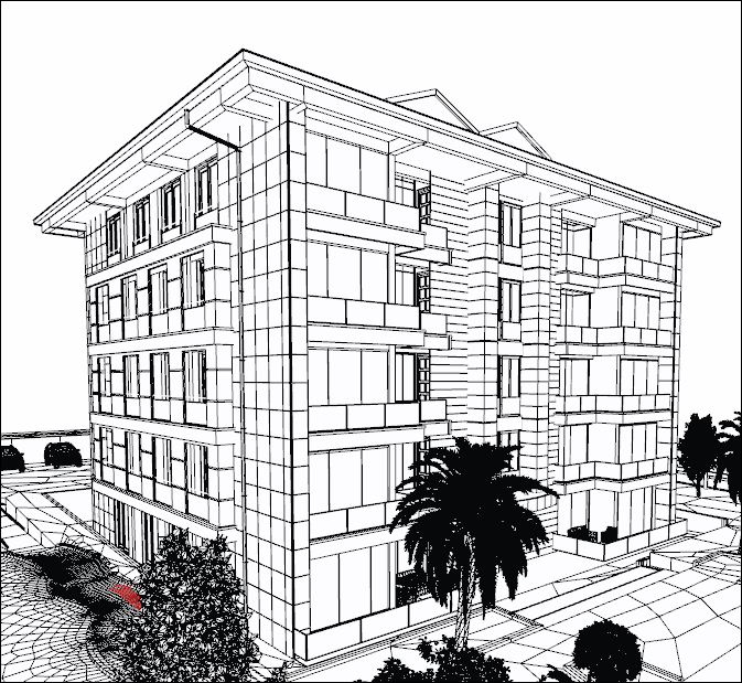
In the hidden line image technique, the object surfaces that enter the image appear with the object drawing colors selected in the relevant object settings.
In the black and white hidden line technique, objects appear in black and white.
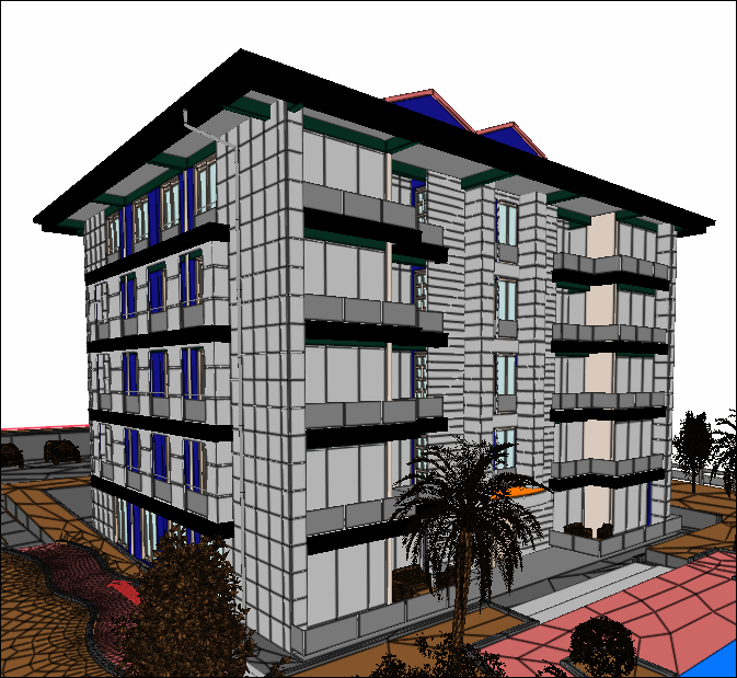
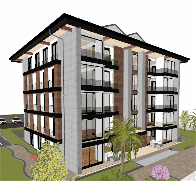
If a solid is selected, the objects entering the image are seen with the material textures assigned to the relevant objects, no boundaries appear between different objects with the same material. If no materials are assigned to the objects, the objects are made solid images with their own line colors.
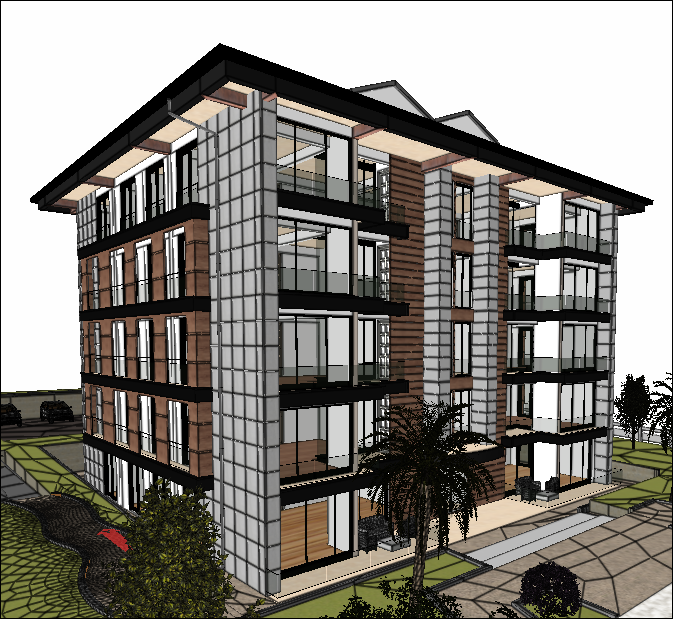
In the solid with edges technique, they are seen with the material textures assigned to the objects, and boundaries appear between different objects with the same material.
The render view of the model can be created with the Render command.
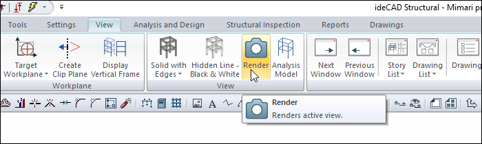
When the Render icon is clicked, the Render Settings dialog will open.
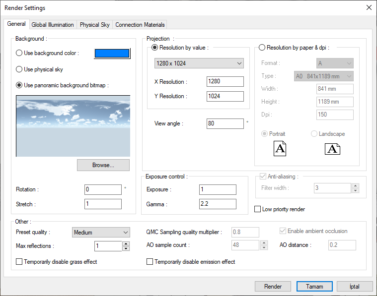
In the dialog, click the Render icon after specifying the settings for the rendering process.
For more detailed information, examine the topics given in the Visualization title.
Next Topic