
How does ideCAD calculate effective length and effective length factor for compression strength according to AISC 360-16?
-
Effective length is calculated automatically by considering unbraced length according to AISC 360-16.
-
The effective length factor, K, is calculated automatically according to AISC 360-16.
-
The effective length check KL<200 is done automatically.
-
Users can define the effective length factor, K, and effective length.
-
The compression strength of steel elements is calculated automatically according to AISC 360-16.
-
The nominal compressive strength limit states of flexural buckling, torsional buckling, and flexural-torsional buckling are controlled automatically according to AISC 360-16.
Symbols
E : Modulus of elasticity of steel = 29,000 ksi (200 000 MPa)
I: Moment of inertia
K: Effective length factor
L: Laterally unbraced length of the member
Lc=KL: Effective length of the member, (= KL)
GA ,Gb: Restraint factors
r: Radius of gyration
Download ideCAD for ACI 318-19
Effective Length
The effective length Lc is obtained by multiplying the Effective length factor, K, and the laterally unbraced member length. The effective length Lc=KL is used to calculate the slenderness of the steel member, KL/r.
For members designed based on compression, the effective slenderness ratio, KL/r, preferably should not exceed 200.
Effective Length Factor
The effective Length Factor, K, is used to compute the slenderness of the compression member. Effective
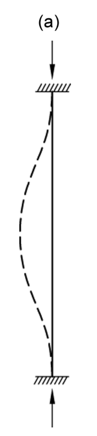
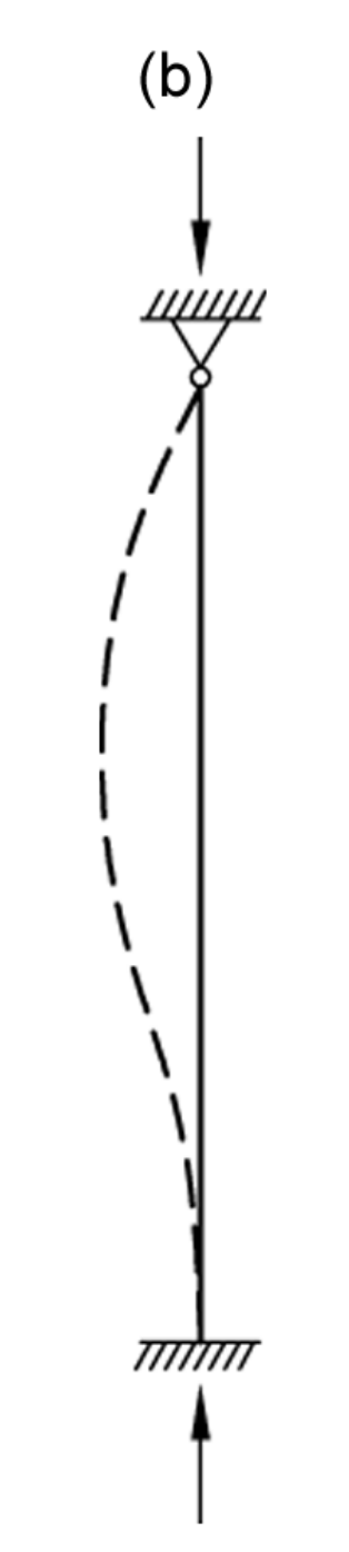
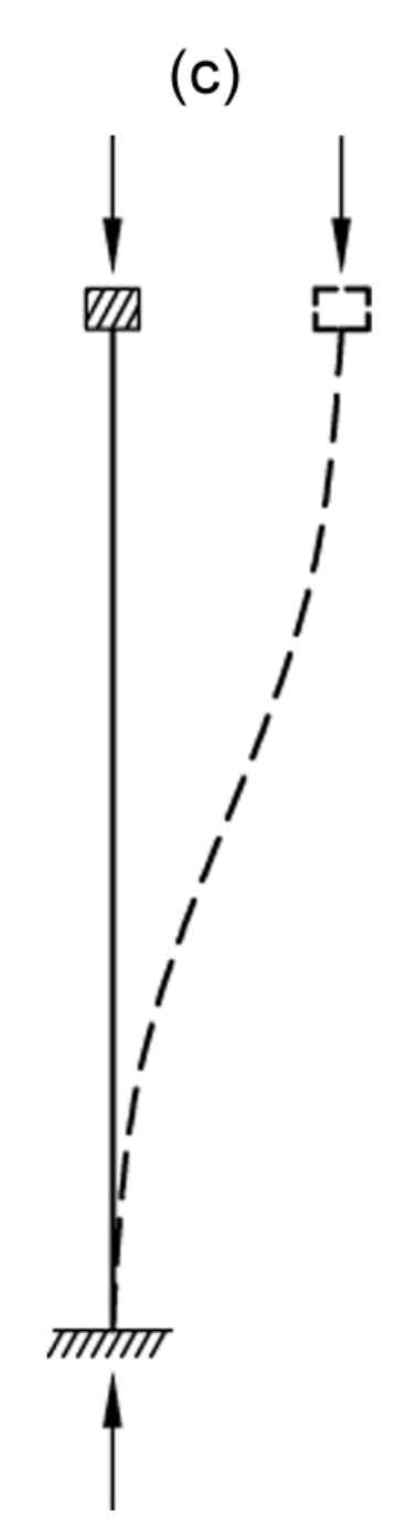
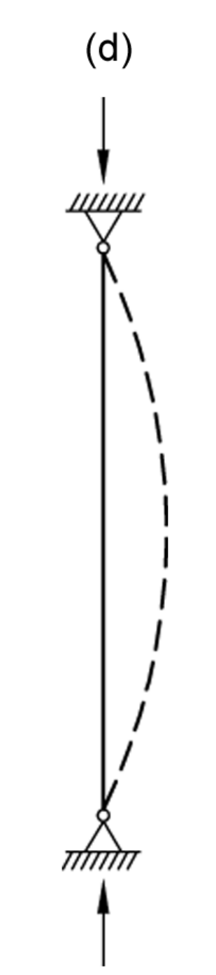
length factors, K, for centrally loaded columns having various idealized end conditions are as follows.
|
Approximate Values of Effective Length Factor, K |
||||||
|---|---|---|---|---|---|---|
|
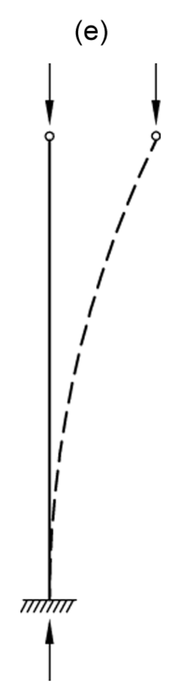
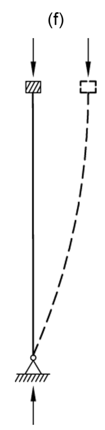
The buckled shape of the column is shown by a dashed line |
|
|
|
|
|
|
|
Theoretical K value |
0.5 |
0.7 |
1.0 |
1.0 |
2.0 |
2.0 |
|
Recommended design value |
0.65 |
0.80 |
1.2 |
1.0 |
2.1 |
2.0 |
|
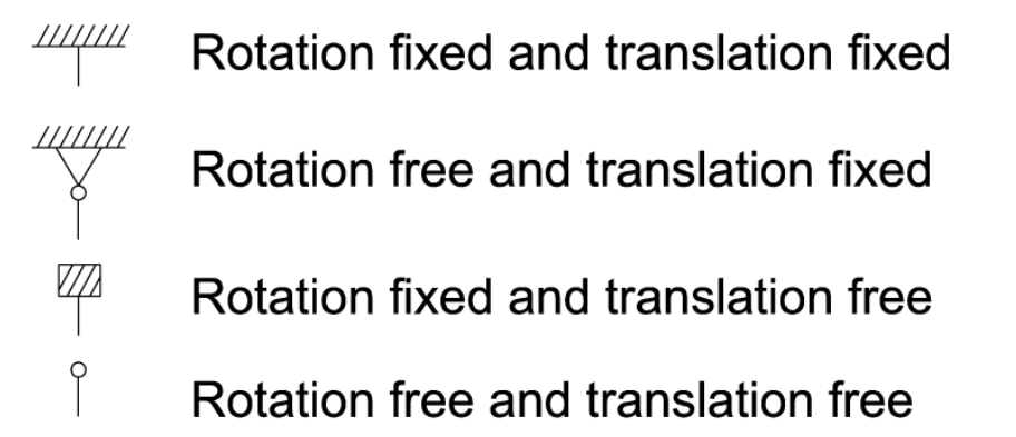
End condition code |
|
|||||
The effective length factor, K, and alignment charts are used for different end boundary conditions, given below.
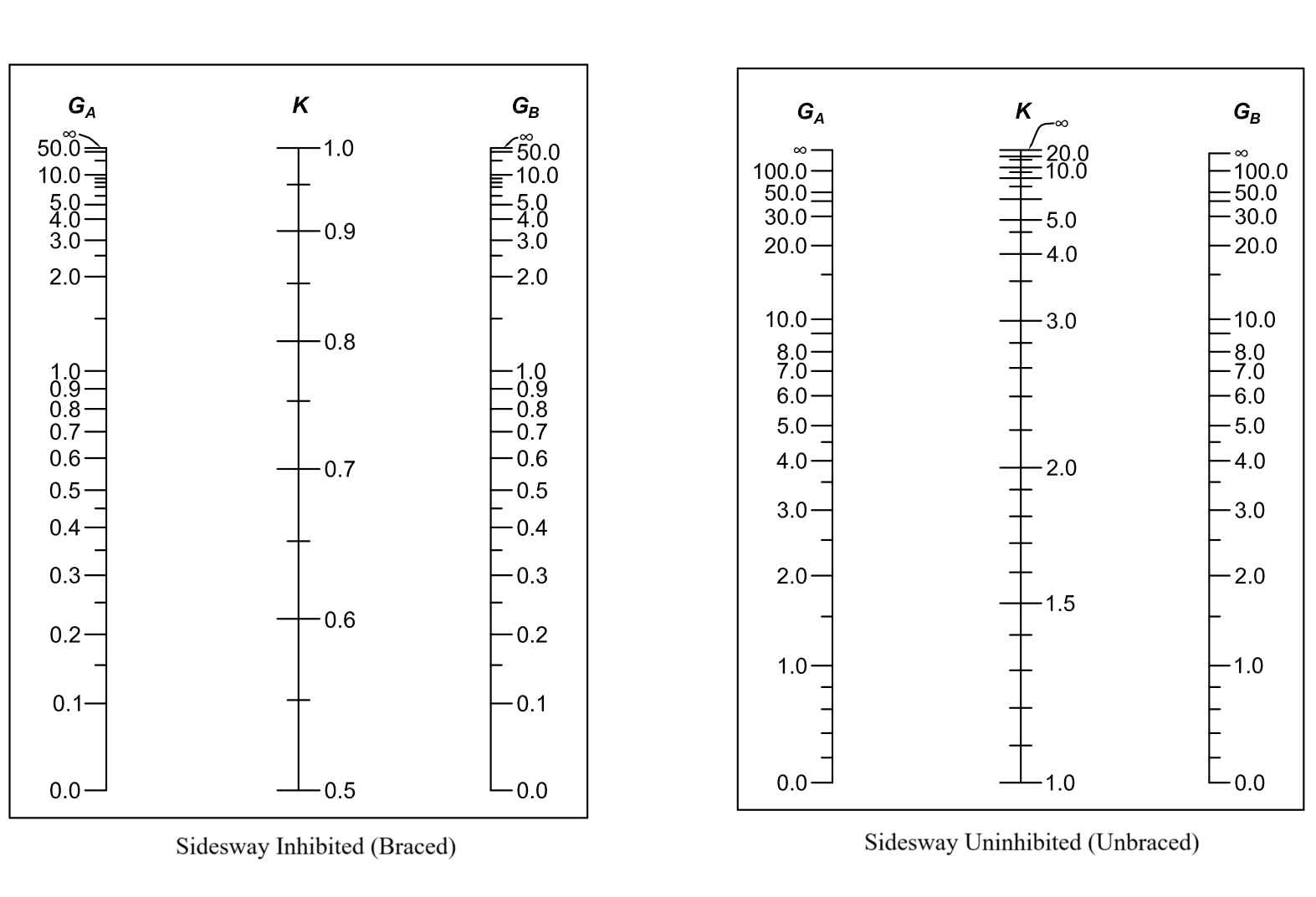
Restraint factors of GA and GB defined for either end of a steel member are obtained as follows.
The subscripts A and B refer to the joints at the ends of the column being considered. The symbol Σ indicates a summation of all members rigidly connected to that joint and located in the plane in which buckling of the column is being considered.
The effective Length Factor, K, for sidesway-inhibited frames, is obtained as follows.
The effective Length Factor, K, for sidesway uninhibited frames, is obtained as follows.