
Single footing reinforcement design results and inadequacy conditions for individual foundations are displayed in the Single Footing Reinforcement dialog. In the Single Footing Reinforcements dialog, foundation reinforcements, soil stresses and slip-punch results are given.
The Place of Single Footing Reinfocement Dialog
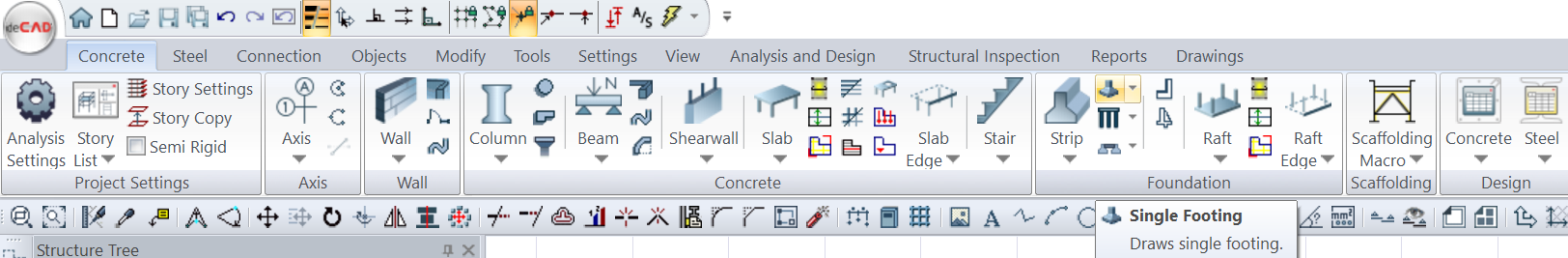
After the analysis, you can access it by clicking the Single Foundation Reinforcements command under the ribbon menu Analysis and Design tab, Reinforced Concrete Design heading .
General Specifications of Single Footing Reinforcements Dialog
|
Summary Summary information about the line where the cursor is located is given in the Name of the dialog in Solid, Name format. 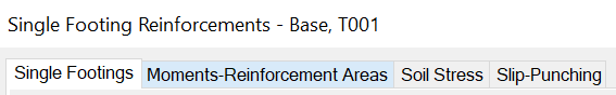
Example Base, T001 |
|
Using the Shift key In this tab, you can select more than one row with the Shift key, enter a value by double-clicking on any cell whose value is open to change, and make that value apply to all selected rows. |
|
Using the Ctrl key The Ctrl key selects the in-between lines one by one. |
|
Reinforcement calculator Calculates the amount of reinforcement in area for the selected diameter and spacing. |
|
Previous The cursor moves to the previous line. |
|
Next The cursor moves to the next line. |
|
Recalculate Rebuilds the element reinforced concrete. Regulation calculations related to reinforced concrete and reinforcement are also made again. For significant changes, it may be more appropriate to repeat the structural analysis instead of reinforced concrete. |
|
OK Saves the changes made and closes the dialog. |
|
Cancel Closes the dialog without saving the changes made. |
Insufficiency Code Description and Recommended Solution
|
Insufficiency Code |
Description |
|---|---|
|
K |
Shear safety is not satisfied.
|
|
M |
The maximum reinforcement ratio is exceeded.
|
|
Zg |
Soil bearing capacity is exceeded.
|
|
As(-) |
Provided reinforcement area is insufficient.
|
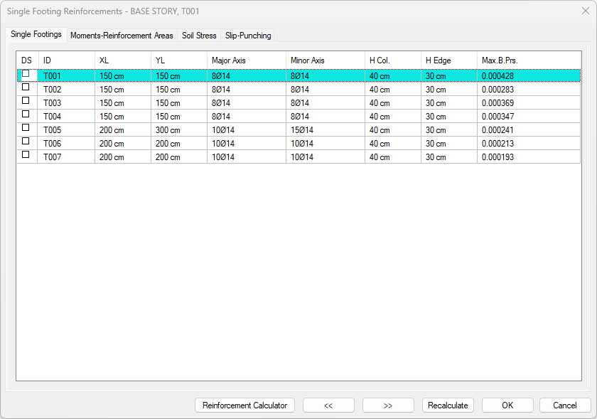
Single Footings Tab
|
Specifications |
|---|
|
DS It is the reinforcement fixing column. If marked, the reinforcements are fixed. The DS is automatically marked when changes are made to the basic reinforcements and the reinforcements remain fixed even after analysis. If DS is not marked, the reinforcements are determined again according to the reinforcement selection conditions after the analysis. |
|
ID 
It is the name of the single footing in the plan. (T001, T101, T010 etc.) In case of negativity, the negation term is added next to the name. Example: T101(Z) |
|
XL 
The dimensions of the single footing. |
|
MSc 
The dimensions of the single footing. |
|
Major Axis 
It is the number and diameter of reinforcement in the major axis direction. |
|
Minor Axis 
It is the number and diameter of reinforcement in the minor axis direction. |
|
H Col. 
It is the height of the section at the column edge. |
|
H Edge 
It is the height of the section on the basic edge. (cm) |
|
Max.B.Prs. 
It is the maximum base pressure value. |
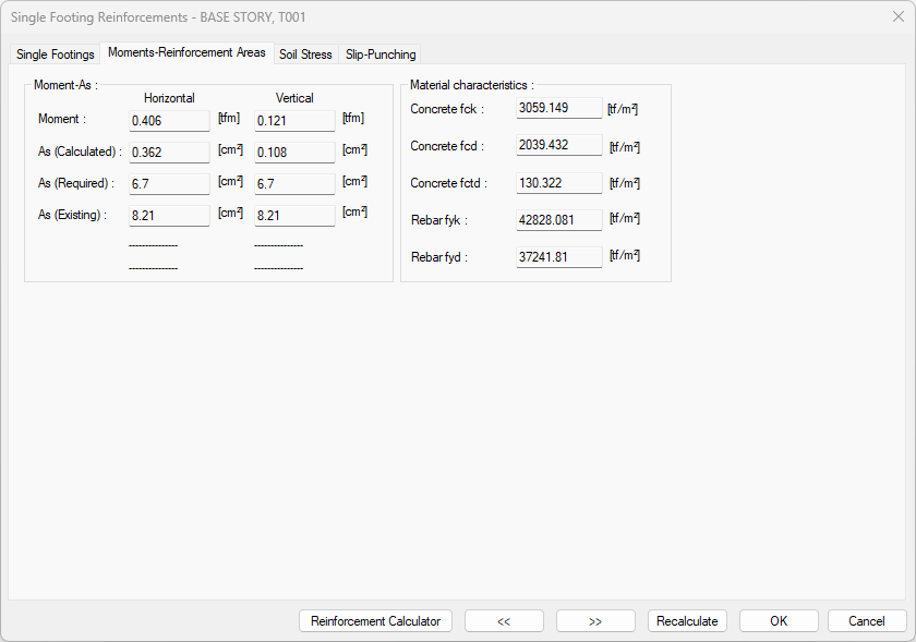
Moments-Reinforcement Areas Tab
|
Specifications |
|---|
|
Moment The design moments in the horizontal and vertical directions of the single footing are shown. |
|
As (Calculated) They are the reinforcement areas calculated from the design moment in the horizontal and vertical directions of the single footing for a width of 1 meter. |
|
As (Required) For 1 meter width, these are the reinforcement areas that should be placed in the horizontal and vertical direction of the single footing as per the specification. |
|
As (Existing) For 1 meter width, they are the existing reinforcement areas in 1 meter in the horizontal and vertical direction of the single footing. |
|
Concrete fck It is the characteristic compressive strength of concrete belonging to a single footing. |
|
Concrete fcd It is the characteristic calculation compressive strength of concrete belonging to a single footing. |
|
Concrete fctd It is the characteristic calculation tensile strength of concrete belonging to a single footing. |
|
Rebar fyk The reinforcement is the characteristic yield strength. |
|
Rebar fyd The reinforcement is the design yield strength. |
Soil Stresses Tab
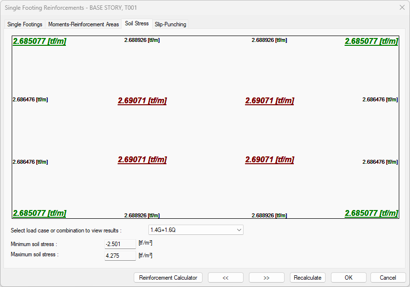
All stress values are listed, from maximum stress to minimum stress, depending on the selection of the loading combination. In some cases, the soil stress may be greater in the middle of the column in a single footing. In this case, you may not see the maximum ground stress value given at the bottom here.
|
Specifications |
|---|
|
Select load case or combination to view results The combination in which the soil stress values are shown is selected. |
|
Minimum soil stress It is the minimum soil stress from all loads. |
|
Maximum soil stress It is the maximum soil stress from all loads. |
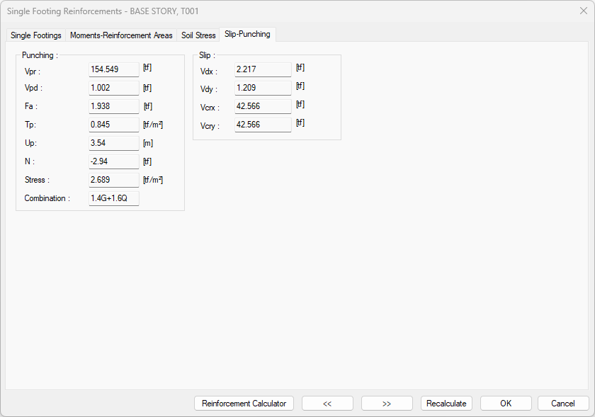
Slip - Punching Tab
|
Specifications |
|---|
|
Vpr Punching Strength. Vpr= gamma * fctd * Up * d (gamma=1 ) |
|
Vpd Punching Load. |
|
Fa Sum of plate loads inside the punching perimeter |
|
Tp Punching stress |
|
Up Punching critical section. |
|
N It is the vertical force of the column multiplied by the load coefficients. If there is no column on the upper floor, zero appears. |
|
Stress It is the soil stress value. |
|
Combination It is the combination of loading that creates the most unfavorable stapling situation. |
|
Vdx The design in the horizontal direction is the shear force. |
|
Vdy It is the design shear force in the vertical direction. |
|
Vcrx It is the shear force that creates the oblique crack in the horizontal direction. |
|
Vcry It is the shear force that creates the oblique crack in the vertical direction. |
Next Topic
Related Topics