
-
By checking the incremental spectrum scale coefficient at each step of the impulse analysis, the last step of the impulse analysis is automatically calculated.
In the Incremental Mode Combining Method, the modal displacements reach their maximum values together in all modes. The cumulative spectrum scale coefficient calculated at the end of each i th thrust step, Whether it exceeds the unit value with the highest value is checked by the following equation. In step (i), it expresses the constant incremental spectrum scale coefficient for all modes.
:art_ölç_kat::f_cizgi_i:
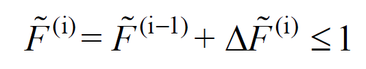
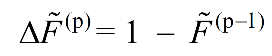
At the end of each step, it is checked whether it exceeds the maximum unit value or not. If the value does not exceed the highest value, the repulsion analysis is continued by going to the next step. If it exceeds, the push step reached is represented by the superscript (p), which is defined as the last push step. Considering that = 1, the incremental spectrum scale coefficient of the last step is calculated with the following equation.
:f_cizgi_p::f_cizgi_i:
However, for ( X ) and ( Y ) earthquake directions, the modal displacements Δd yn(p)and Δdxn(p)in the nth mode described in Determination of Modal Pseudo-Acceleration, Modal Displacement Increment and Constant Scale Factor, need to be redefined in the final push step as follows.
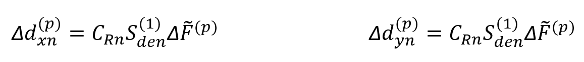
Any mode in C Rn case of> 1 S as the earthquake data from (1) instead of C R S de (1) received. This situation is shown in the above equation. Since the earthquake data is taken from C Rn S as (1) , the and Their size should be calculated using (1) from C Rn S. In this case, the displacement, plastic deformation or internal force values calculated for the last step (X) and (Y) are calculated for earthquake loads as shown in the following equation.
:r_cizgi_yi::r_cizgi_xi:

C Rn denotes the spectral displacement ratio of the nth mode. TBDY is calculated as defined in Annex 5B.3.4 of Chapter, as follows.

In this relation, T 1 is the natural vibration period belonging to the 1st mode. However, since the ARSA method is a multi-mode impulse analysis, C Rn values should be calculated using the vibration periods of each nth mode .
The T B value is the horizontal elastic design acceleration spectrum corner period value TBDY described in Section 2.3.4.1 .
R y expresses a magnitude depending on the yield strength obtained directly from the thrust calculation. TBDY is calculated for each nth mode with the following equation as stated in Annex 5B.3.2 .
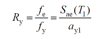
In this relation, f e and S ae (T 1 ) represent the elastic strength demand and the corresponding elastic spectral acceleration, f y and a y1 represent the yield strength and the corresponding pseudo-acceleration of yield. The graph below shows the required values (S ae (T 1 ) and a y1 ) to obtain R y , with the vertical axis spectral acceleration and the horizontal axis spectral displacement .

Next Topic
Related Topics