
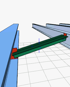
With the Stay Connection (Secondary Beam) command, beam-beam or beam-secondary beam connection is defined.
Opposing steel beams or steel beams connect the secondary steel beams with angle plates.
Location of the Defining a Stay Connection (Secondary Beam) Command
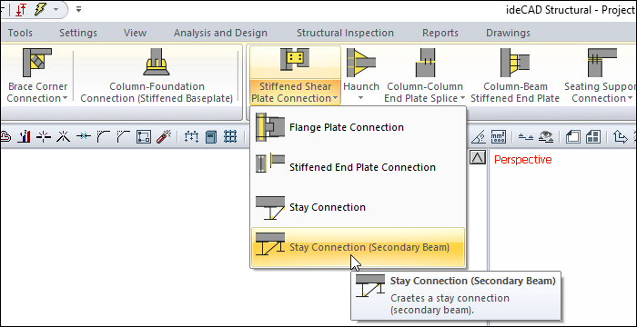
You can access it under the Ribbon menu, Connection tab, Experimentals title.
Usage Steps
-
From the Connection menu, click the Stay Connection (Secondary Beam) icon.
-
First choose the main beam. Then choose the other beam or subsidiary beam parallel to it.
-
The program will ask the distance to start. The value to be given is the distance to the left end.
-
If the distance is given and OK is clicked, the connection will occur with default settings.
Location of the Stay Connection (Secondary Beam) Settings Dialog
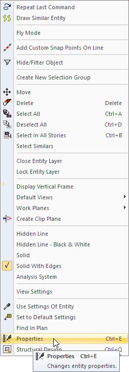
Select the connection and click the right mouse button. Click the Properties line from the right click menu that opens.
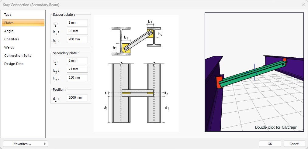
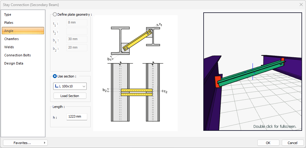
Stay Connection (Secondary Beam) Settings Dialog
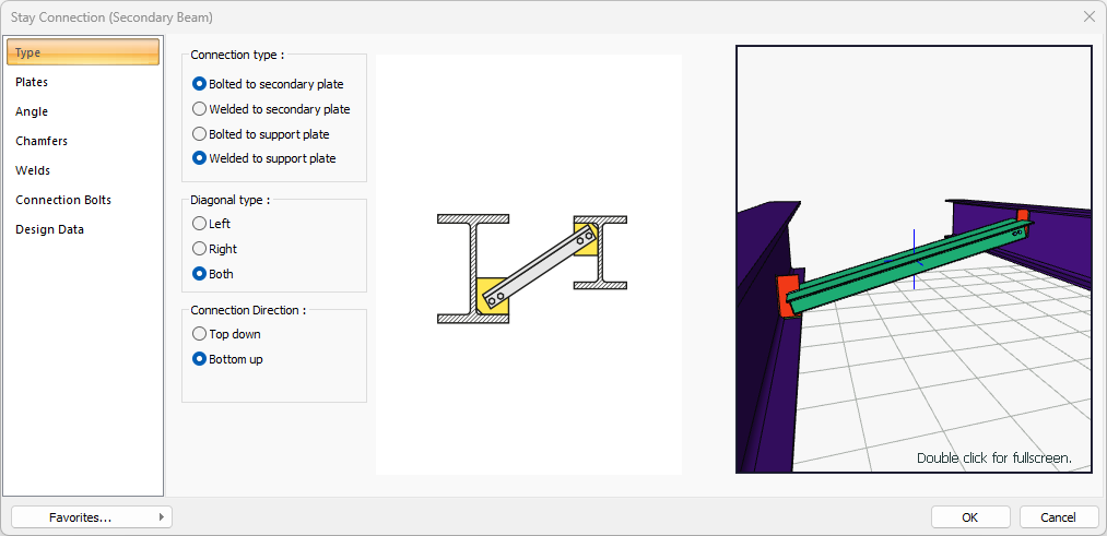
Type Tab
|
Specifications |
|---|
|
Connection type 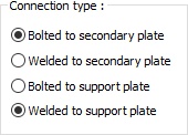
Connection type is selected for support and secondary plate. |
|
Diagonal type 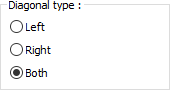
It is chosen whether the diagonal will be on the left or right or both sides. |
|
Connection direction 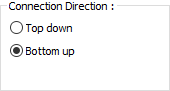
It is selected whether the connection will be from top or bottom. |
|
Schematic drawing 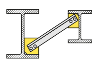
Connection and placement values are shown on the schematic drawing. |
|
Preview 
There is a preview of the connection. The selection made and the entered values can be followed simultaneously in the preview. |
Plates Tab
|
Specifications |
|---|
|
Support plate 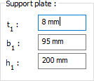
The support plate is determined by entering the value. The values to be entered are shown in the schematic drawing. |
|
Secondary plate 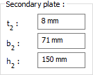
The secondary plate is determined by entering the value. The values to be entered are shown in the schematic drawing. |
|
Position The location of the secondary beam is determined by entering the value. The values to be entered are shown in the schematic drawing. |
|
Schematic drawing 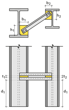
Connection and plate values are shown on the schematic drawing. |
|
Preview
There is a preview of the connection. The selection made and the entered values can be followed simultaneously in the preview. |
Angle Tab
|
Specifications |
|---|
|
Define plate geometry 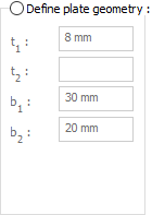
If the option is selected, it is determined by entering the angle values. The values to be entered are shown in the schematic drawing. |
|
Use section 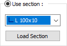
By selecting the option, one of the ready-made L profiles is selected from the list as an angle. By clicking on the load section button, you can reach the ready section library and reach the list of American and European finished rolling sections and select from the list. |
|
Length 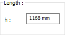
The angle length to be used is determined by entering the value. |
|
Schematic drawing 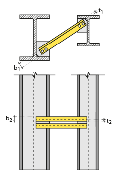
Connection and plate values are shown on the schematic drawing. |
|
Preview
There is a preview of the connection. The selection made and the entered values can be followed simultaneously in the preview. |
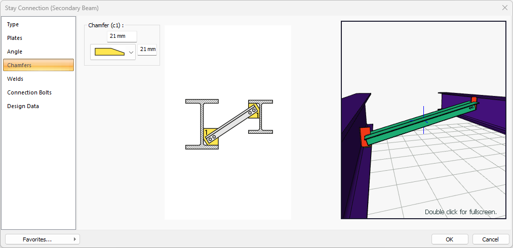
Chamfers Tab
|
Specifications |
|---|
|
Chamfer (c1) 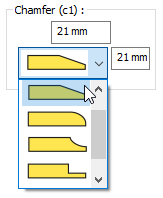
For easy assembly of the plates in the field, the use of slope, slope type and geometric properties are determined by entering the value. |
|
Schematic drawing 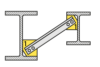
Connection, notching and cutting values are shown on the schematic drawing. |
|
Preview
There is a preview of the connection. The selection made and the entered values can be followed simultaneously in the preview. |
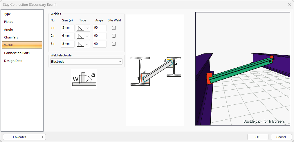
Welds Tab
|
Specifications |
|---|
|
Welds 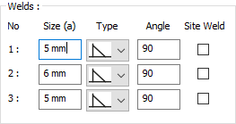
The thickness, type and angle values of the welds to be made at the connections are given. The information on whether it will be done on the construction site or not is entered. |
|
Weld electrode The strengths of the welding electrodes are defined in the design inputs. The strength of the main element in the weld joint is controlled under the condition that it has less strength than the weld strength. If necessary, click the list and define "Create New…". To create the welding electrode, give the information "Name" and "Weld metal tensile strength" in the dialog that opens after clicking "Create New". Welding geometry is determined automatically by the program. These properties can be changed to easily determine the connection properties. Geometry features are in accordance with industry standards and in the form specified in AISC. |
|
Schematic drawing 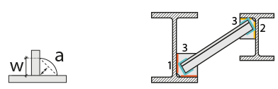
Connection and weld values are shown on the schematic drawing. |
|
Preview
There is a preview of the conection. The selection made and the entered values can be followed simultaneously in the preview. |
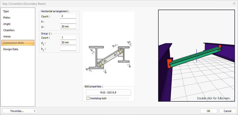
Connection Bolts Tab
|
Specifications |
|---|
|
Horizontal arrangement 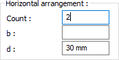
The horizontal arrangement distance value of the bolts is entered. The values to be entered are shown in the schematic drawing. |
|
Group 1 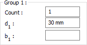
Distance values of bolts to beam and other bolts are entered. The values to be entered are shown in the schematic drawing. |
|
Bolt properties 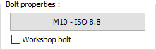
The Hole and Bolt Parameters dialog is opened by clicking on the bolt properties button. The bolt properties are set in this dialog. |
|
Schematic drawing 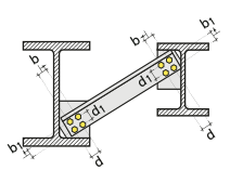
Connection and bolt arrangement values are shown on the schematic drawing. |
|
Preview 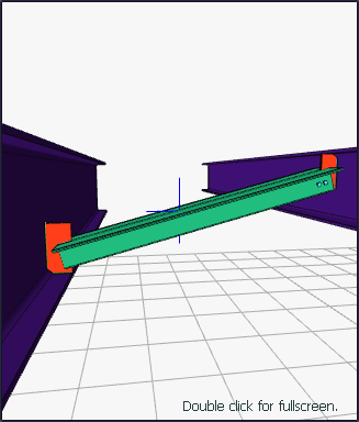
There is a preview of the connection. The selection made and the entered values can be followed simultaneously in the preview. |
Design Data Tab
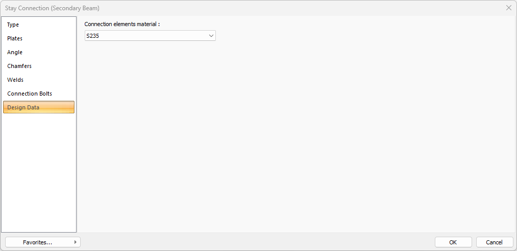
In the design data, the connection elements material is defined. The condition that the main element in the weld joint has less strength than the weld strength is controlled.
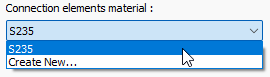
If necessary, click the list and define "Create New…". To create the connection elements material, give the information material definitions and values in the dialog that opens after clicking "Create New".
Next Topic