
-
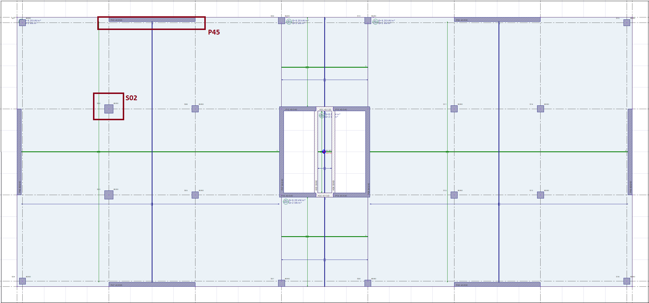
As an example, the punching calculation of the 11th-story slab S03 without internal column beams will be made. In addition, it will be shown that the seismic forces are transferred safely from the slab to the shearwall in the strong direction of the 10th-story P45 shearwall.
Punching Checks
-
In slab-column combinations in non-beamed slab systems, the value obtained by multiplying the total bending moment transferred to the column in the direction taken into account at the story level under the effects of earthquakes with vertical loads, D, together with the vertical loads according to TBDY 7.11.8, with the bending reinforcement value of 1-γf the value obtained by multiplying by the coefficient is assumed to be transmitted through the punching stresses. Accordingly, assuming that the shear stresses in the slab vary linearly with respect to the geometric center of the punching circumference in the direction of loading, the idealized distribution of shear stresses acting on the slab along the punching circumference up can be calculated. This account will be explained in detail later.
-
Since the columns in the building are square, b1 = b2 .
-
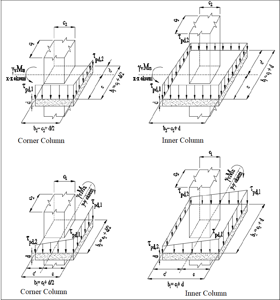
The above figure shows the unbalanced moment distribution in the corner and inner column. The drawn shear stresses are the stresses perpendicular to the floor plane.
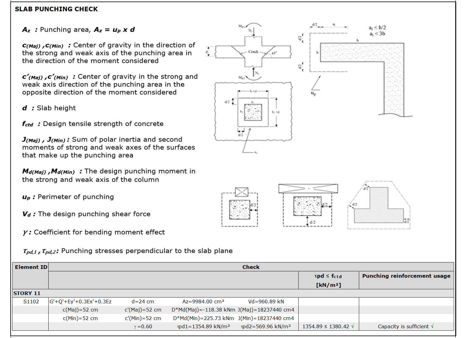
Az = Area of punching circumference up multiplied by useful height d
J = Sum of polar moments of inertia and second moments of the surfaces forming the Az field
80/80 Inner Column Punching Control
-
Slab thickness: 27 cm
-
Slab cover: 3 cm
-
Material : C35/S420
-
fctd = 1380.42 kN/m2 (Concrete design tensile strength)
The slab useful height, d, is calculated;
d = ( Slab thickness - Slab cover ) = 27 - 3 = 24 cm
Column dimensions
c1 = 100 cm c2 = 50 cm
The punching circumference (up) is calculated at a distance d/2 from the column surface and is shown in the image below. In this case, the following operations are performed to find the edges of the punching circle (b1, b2).
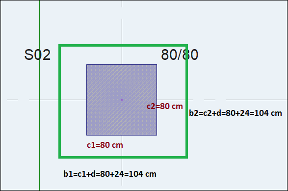
In this case, the punching area (Az) obtained by multiplying the punching circumference, (up), and the punching circumference by the slab useful height, d, is calculated as shown below.
The following operations are performed to find the J(maj) value.
c(maj) is the center of gravity distance perpendicular to the moment vector, which is considered when finding the J value (J(maj)) on the strong axis of the section. Since the stapling circumference is rectangular, the c(maj) value is calculated as follows.
The polar inertia and second moments of inertia are calculated as follows, respectively.
In this case, the sum of the polar inertia and second moments of inertia about the strong (major) axis of the section, J(maj), is found as follows.
Since it is a square column, the values calculated above will be used in both directions.
Finding Punching Stresses
The forces to be considered for punching stresses and the values obtained from the hand geometry are given below.
-
Vd = 961.65 kN
-
DMd(maj) = 118.38 kNm
-
DMd(min) = 225.73 kNm
-
Az = 0.9984 m2
-
γf(maj) = 0.6
-
γv(maj) = 0.4
-
γf(min) = 0.6
-
γv(min) = 0.4
-
J(maj) = 18237435 cm4
-
J(min) = 18237435 cm4
-
c(maj) = 0.52 m
-
c(min) = 0.52 m
-
c'(maj) = 0.52 m
-
c'(min) = 0.52 m
The punching stresses are found by substituting all the above values in the stress formulas together with the internal forces essential to the punching design.
The largest absolute value of τpd,1, τpd,2 is τpd,1 = 1354.89 kN/m2. This obtained value is compared with the fctd value, which is the concrete design tensile strength.
τpd,1 = 1354.89 kN/m2 < fctd = 1380.42 kN/m2
Upholstery stapling strength is sufficient. These values can also be compared with the report results.
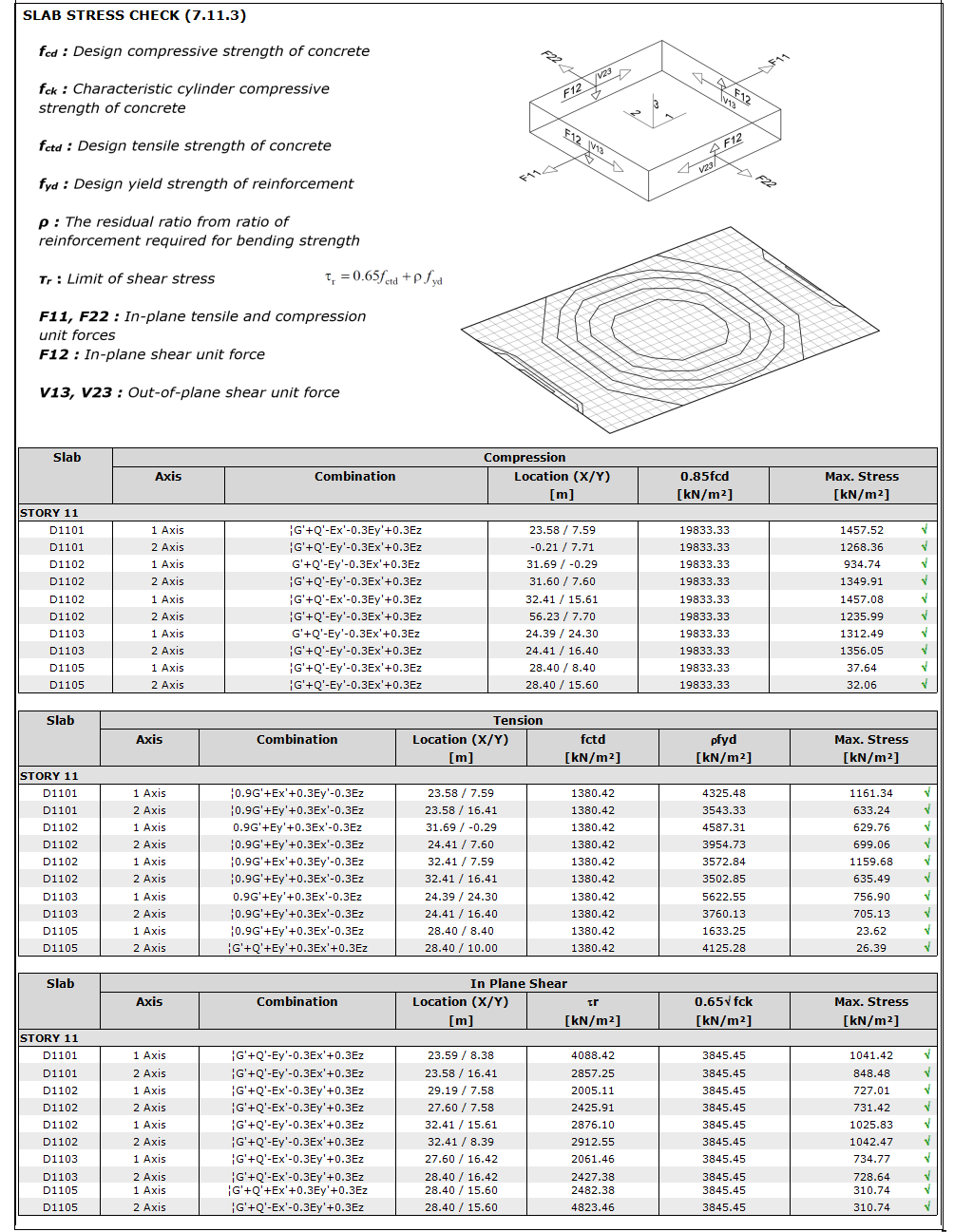
Slab Stress Control (7.11.3)
-
The slab in-plane stress limit values given in TBDY 7.11.3 are checked.
Compression Stress Control
-
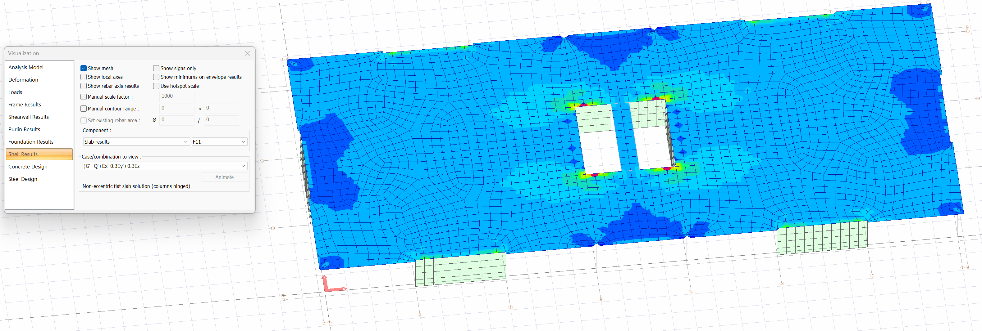
The most unfavorable situation arises in the !G'+Q'-Ex'-0.3Ey'+0.3Ez load combination obtained from the semi-rigid diaphragm solution. It is seen that the greatest stress value of the slab due to the negative Ex' seismic load is close to the core shearwall at the right edge of the slab. In this case, the F11 values on the 1 axis should be read at this point.
-
In this case, taking into account the excess strength coefficient, the F11 value formed in the load combination !G'+Q'-Ex'-0.3Ey'+0.3Ez is calculated as follows.
Compressive stress, F11/d = 385.0605/0.27 = 1457.08 kN/m2
-
According to TBDY Article 7.11.3, this value should be less than 0.85*fcd.
0.85*fcd = 0.85*23.33*103 = 19833.33 kN/m2 > 1457.08 kN/m2 √
-
The report and the manual account are consistent. The program is controlled by doing this process in reverse. In this case, F11 can be calculated by reading the load components of the most unfavorable combination written in the report over the meshes in the coordinates given in the report. In this, the XY coordinate indicator in the program is 0-0 coordinates in whichever box is in the plan. For example, the mesh to be read for this tile is marked as in the image below.
Tensile Stress Control
-
The most unfavorable results were obtained from the semi-rigid diaphragm solution under the effect of the load combination !0.9G'+Ex'+0.3Ey'-0.3Ez. The F11 value calculated by considering the overstrength factor is read as 313.1406 kN. In this case, the tensile stress is
F11/d = 313.1406/0.27 = 1159.68 kN/m2
Stress value 1159.68 <f ctd = 1380 kN / m 2 √
-
According to TBDY Article 7.11.3, if this value exceeds the fctd value, the yield strength of the reinforcement remaining from what is required for the flexural strength of the slab should not exceed the yield strength ρfyd. This ratio has not been checked as it provides a stress value.
-
In the slab report, this control is detailed as follows.
In-Plane Shear Stress Control
-
The most unfavorable situation was obtained under the effect of the load combination !G'+Q'-Ey'-0.3Ex' +0.3Ez obtained from the semi-rigid diaphragm solution. The F12 value is calculated by considering the overstrength factor. In this case, the in-plane shear stress is,
F12/d = 1042.47 kN/m2
-
According to Article 7.11.3 of TBDY, in-plane shear stress shall not exceed the limit value given by Equation 7.25.
Since calculations were made on 1 slab calculation axis, the area of reinforcement (Φ14/20) on this axis was found to be 18.47 cm2 for 1 m length. The reinforcement required for bending strength is read as 5 cm2/m in an area close to the shearwall edge. In this case, the ratio of reinforcement remaining from the required for flexural strength is ρ,
τr = 0.65fctd + ρfyd = 0.65 * 118.97 + 0.00962 * 37242.076 = 4088.42 kN/m 2.
-
According to Article 7.11.3 of TBDY, the in-plane shear stress should not exceed 0.65(fck)1/2.
0.65(fck)1/2 = 0.65*(35)1/2 = 3.845 MPa = 3845.45 kN/m2
-
In-plane shear stress value
-1041.42 kN / m 2 < 4088.42 kN / m2 and
-1041.42 kN/m2 < 3845.45 kN/m2 √
-
These values are detailed as follows in the slab report.
Control of Loads Transferred from Slabs to Shearwall (7.11.5)
-
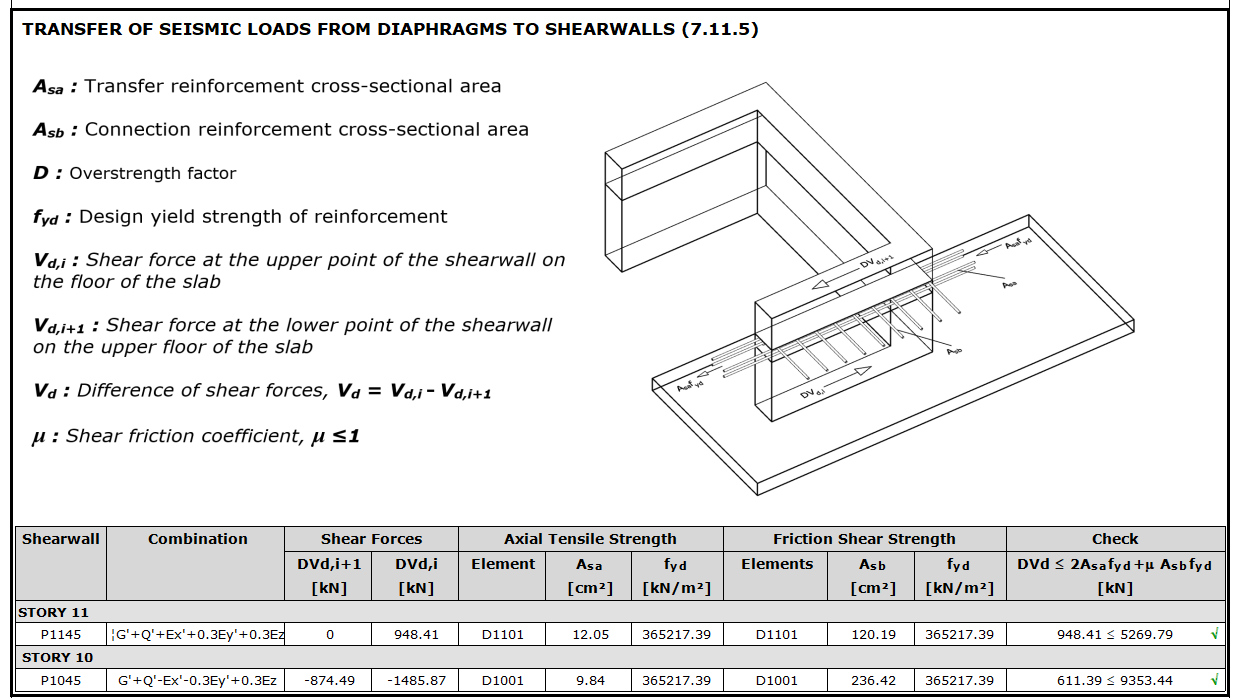
According to TBDY 7.11.5, the seismic force to be transferred from the slab to the shearwall or the shearwall arm in a strong direction in non-beam slab buildings is calculated as the difference of D*Vd shear forces that occur in the lower and upper sections of the story level and the seismic effects will be increased by D. This force difference, the sum of the axial tensile strength formed by the slab reinforcement to increase than required for shearwall potent direction from both sides of the penetrating and bending strength 2Asafyd shear consisting of the remaining floor slab reinforcement required for shearwall inflection at the junction resistance with the floor friction resistance of μAsbfyd. It will not exceed the sum of μAsbfyd.
-
The shear friction in slab and shearwall connection is calculated in accordance with TS 500, the value of μ≤1.0 is used for the friction coefficient. It is taken into consideration that the amount of transfer reinforcement can be reduced by starting from the wall surface where the reinforcement is stuck and as it moves away from the wall face.
-
As mentioned in Section 7.11.5 of TBDY, the seismic force (DVd) to be transferred to the shearwall in a strong direction, the seismic effects calculated taking into consideration the overstrength factor, D, at the lower section of the story level (DVd,i) and the upper section of the story level (DVd, i + 1). It is calculated as the difference in shear forces occurring.
DVd = DVd,i - DVd,i+1
-
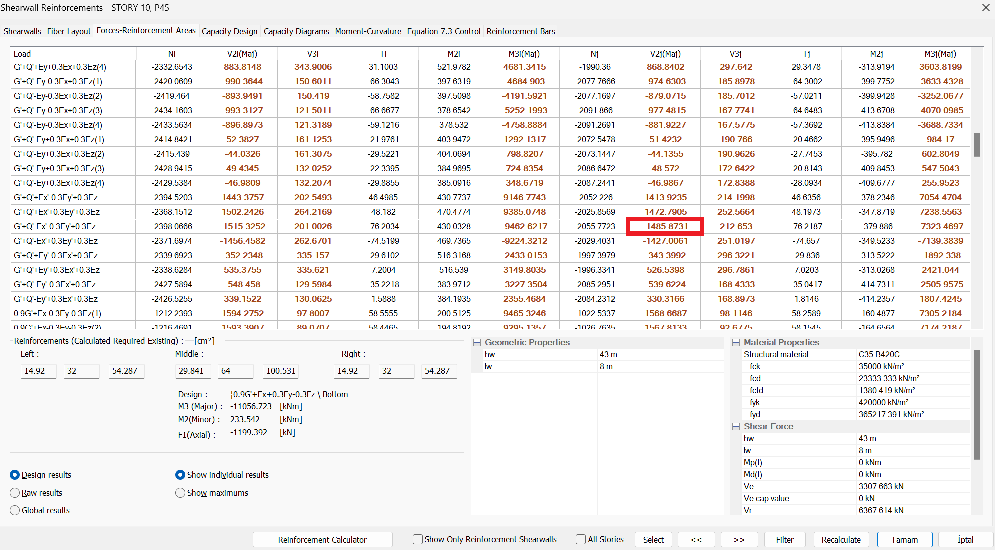
In the above image, the concrete design 10th story from the shearwall section is at the upper end of the P45 shearwall; under the effect of G'+Q'-Ex'-0.3Ey'+0.3Ez load combination, the shear force DVd calculated under the combined effect of earthquake loads calculated by taking into consideration the vertical loads and the overstrength factor, D was calculated DVd,i = -1485.87.
-
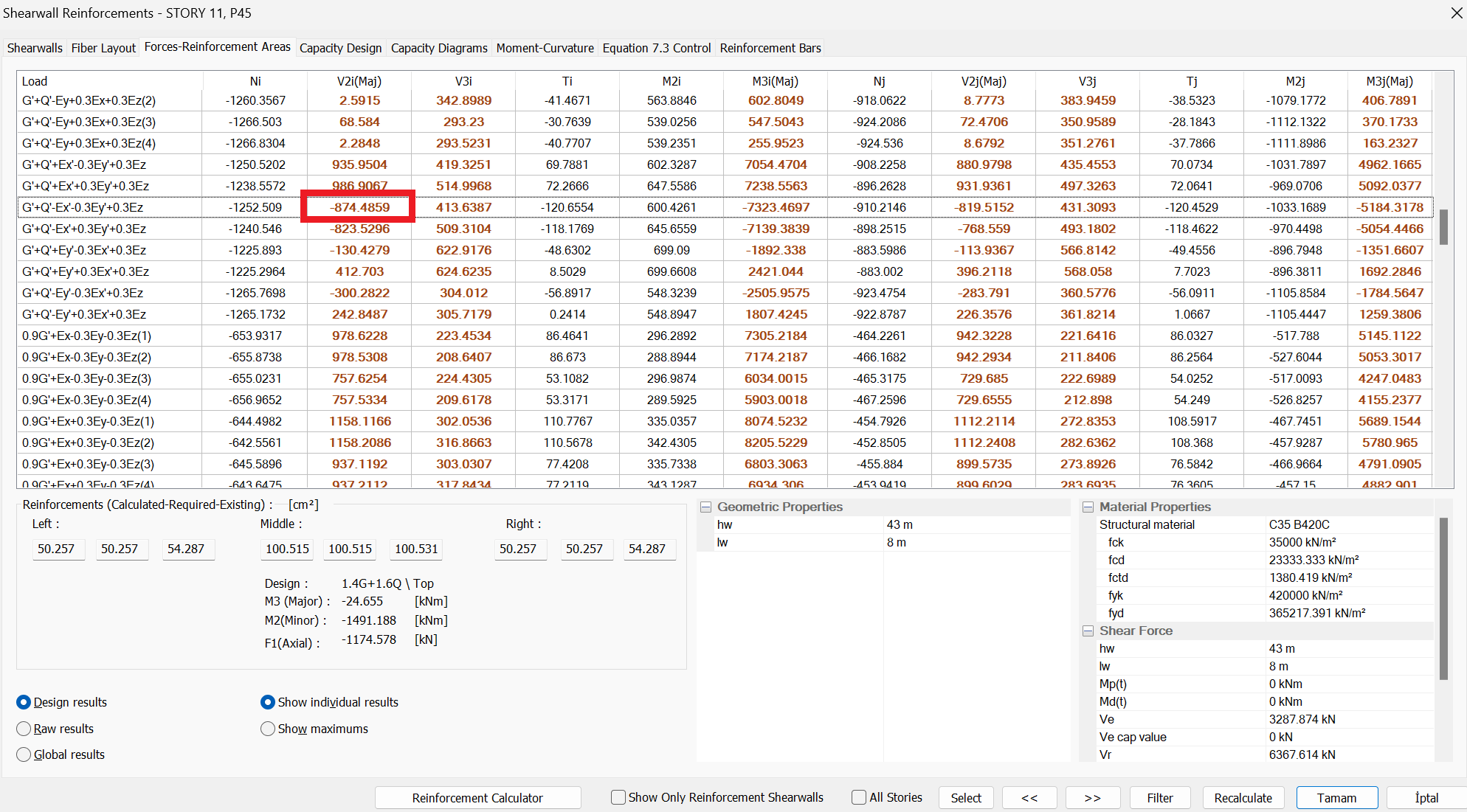
11th floor P45 shearwall at the lower end; under the effect of G'+Q'-Ex'-0.3Ey'+0.3Ez load combination, the shear force DVd calculated under the combined effect of earthquake loads calculated by taking into consideration the overstrength factor, D was calculated as DVd,i+1 = -874.48 kN.
In this case, the seismic force to be transferred to the shearwall arm in the strong direction;
DVd = DVd,i - DVd,i+1 = (-1485.87) - (-874.49) = -611.39 kN
-
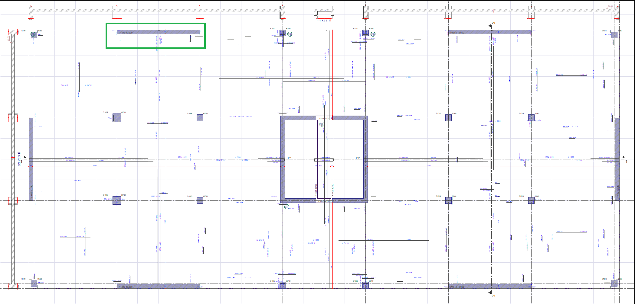
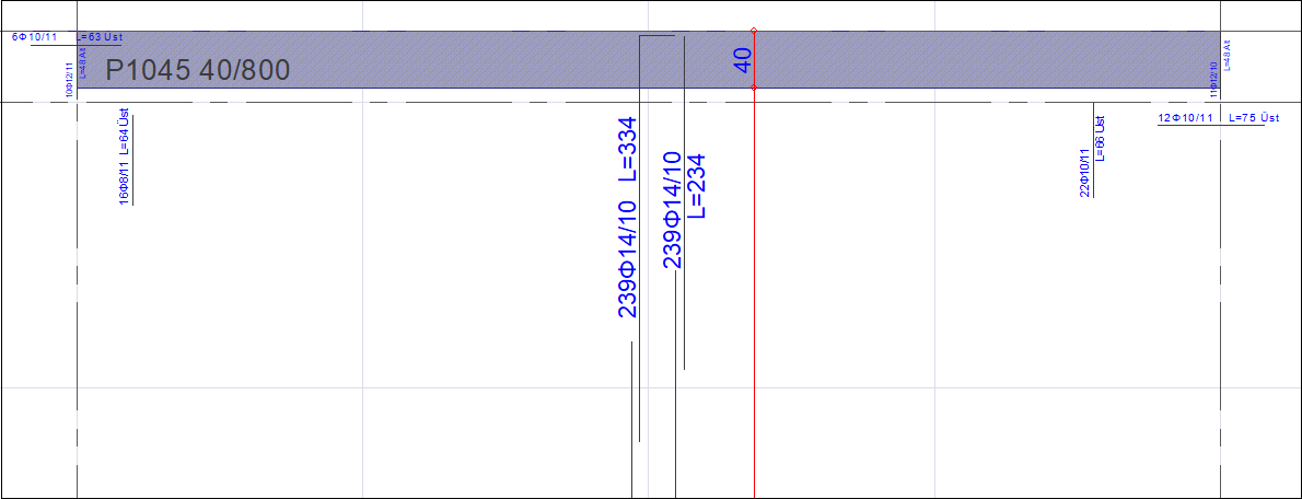
The reinforcement layout of the slab is shown in the picture below. According to this reinforcement layout, Transfer Reinforcement Area, Ahr and Connection Reinforcement Area Asb are calculated as shown below.
-
Transfer Reinforcement Area, Asa is the area of reinforcement that is stuck to the wall in a strong direction from both sides and remains from the required bending strength. It can be considered that slab reinforcements Φ14 / 10, which are connected to the P1045 shearwall from the strong and weak axis and that meet the overlap length condition, are stuck in the strong axis of the wall. In this case, it can be assumed that there are 16 reinforcements in total. In this case, the area of reinforcement obtained for 1 m length is;
16 * (π * (14 2 /4)) = 2463 mm 2 is located in.
-
In the program, from the finite element results G '+ Q'-Ex'-0.3Ey' + 0.3Ez combination, the area of reinforcement required for bending in the slab in the P1045 wall end region was read as approximately 19 cm2/m = 190 mm2/m.
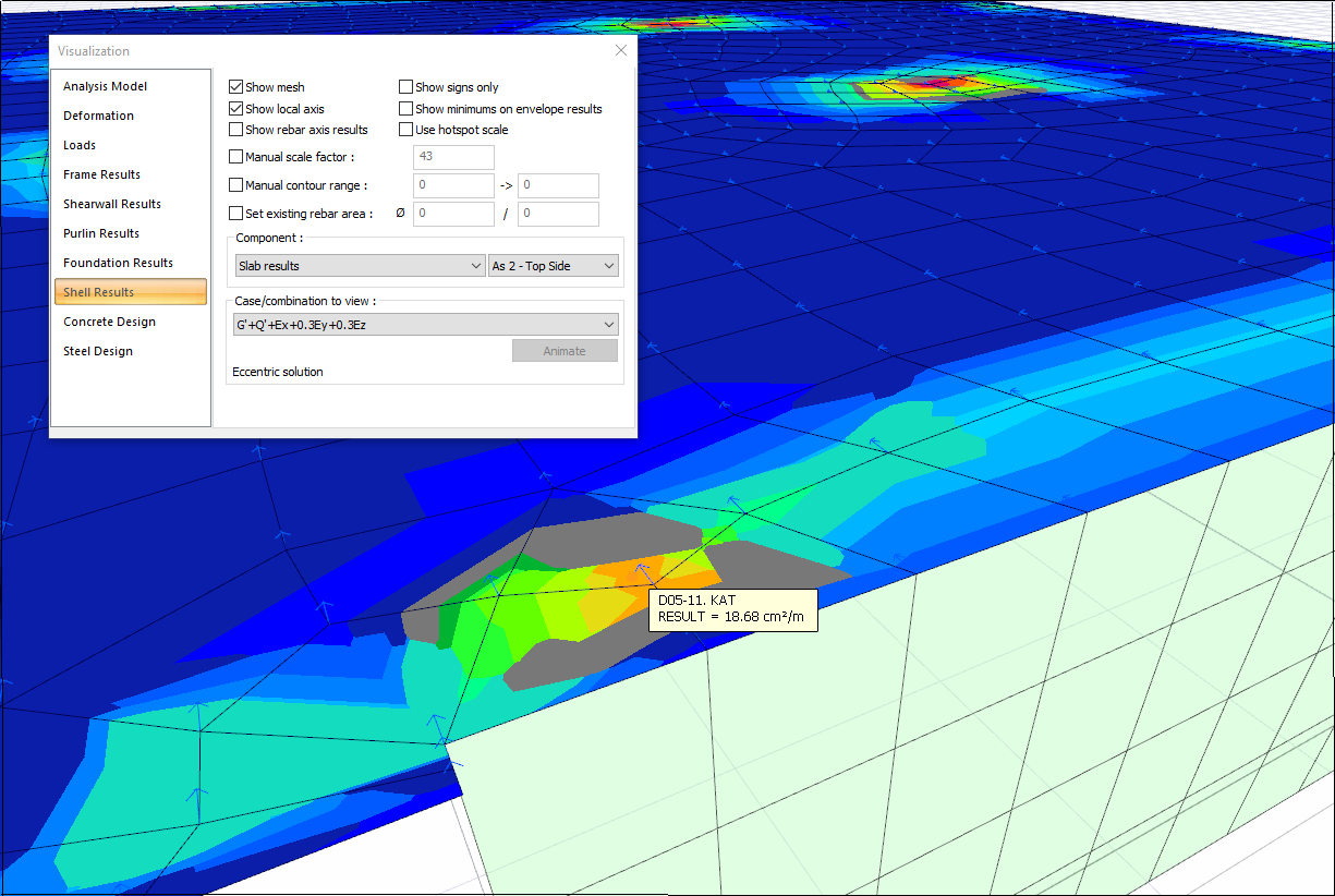
Note: Due to the difficulty of making precise readings on finite element results, it may not be possible to match the values given in the program report exactly. Because of the more precise calculation, the values given in the program report are more accurate.
-
Transfer reinforcement area, Asa and connection reinforcement area, Asb sum of the axial tensile strength produced by the network equipment after making (2Asafyd ) and the connection reinforcement formed by shear friction Strength (μAsbfyd ) The sum DVd shall not exceed.
-
µ is the shear friction coefficient. According to TS 500 Table 8.1, it is taken as µ = 1.4 for cast concrete. However, as stated in Article 7.11.5 of TBDY, the value of µ≤1 will be used, so µ = 1.0.
-
In this case, the seismic force control to be transferred from the slab to the P1045 shearwall arm located on the 10th story in a strong direction is done as follows.
2Asafyd + µAsbfyd = [ 2*9.84*10-4*365217 + 1*236.42*10-4*365217 ]= 9353.44 kN
Since DVd = 611.39 kN < 2Asafyd + µAsbfyd = 9353.44 kN, the force is transferred safely.
-
In the slab report, the relevant control is reported as follows.
Next Topic