
ICONS
A wp = Total cross-sectional area of vertical punching reinforcement on the punching perimeter
A z = Punching area
b 1 = Punching circumference length in the loading direction
b 2 = Punching circumference length perpendicular to the loading
d = Slab useful height
D = Strength Excess Coefficient
f ctd = Design of concrete tensile strength
u p = Punching circumference Shear force based on punching calculation τ pd, 1
V d =
= Design basis punching stress
τ pd, 2 = design basis punching stress
γ v = coefficient reflecting the effect of cutting the stapling account
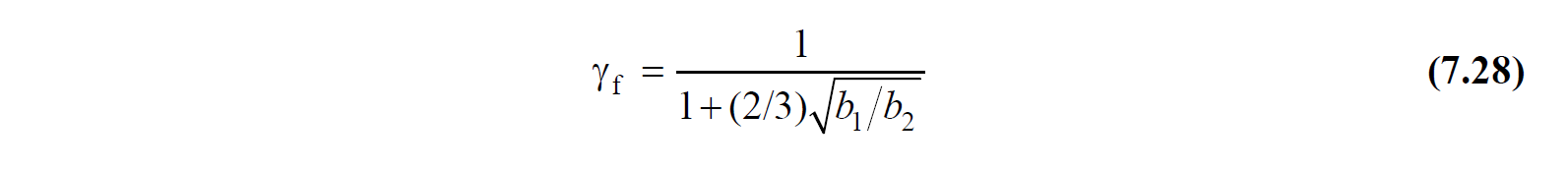
γ f = coefficient reflecting the effect of bending Punching account
ρ = Cross section area of punching reinforcement in unit area
TBDY Article 7.11.8 - without girders plaques in systems in floor-column joints, along with the vertical withstand Redundancy Factor D amplified the earthquake in the direction taken into consideration column at the floor under the effect γ of the total bending moment transferred f with the flexural reinforcement value obtained by multiplying the coefficient 1 - With the assumption that the value obtained by multiplying γ by the coefficient f is transferred by the punching (shear) stresses and with the assumption that the shear stresses in the slab change linearly according to the geometric center of the punching perimeter in the loading direction, the punching perimeter for the floor (u pThe idealized distribution of shear stresses across) can be calculated. The highest shear stress value obtained from this calculation can be used as the design basis τ pd value in the punching control of the slab.
TBDY Article 7.11.9 - In the calculation of the total bending moment transferred to the column at the floor level, the bending moment balancing the bending moments in the upper and lower column sections of the slab-column joint shall be taken into account. γ f in the coefficient calculation, rectangular dimensions of the punching environment, were taken into account in the loading direction B 1 and loading perpendicular b 2 including, Eq. (7.28) will be calculated by. Γ f = 0.60 will be used for columns of circular cross section .
If the condition of TBDY Article 7.11.10 - τ pd ≤ f ctd is not met and the plate thickness is not less than 250 mm, the punching strength of the slab can be increased by using reinforcement. However, in this case, the contribution of concrete to the punching strength will be reduced to 0.5f ctd in terms of shear stress , the contribution of the reinforcement to the punching strength will not be less than f ctd , and the punching strength of the reinforced slab will be at most 1.5f ctd . When shear wedges are used as punching equipment, the contribution of concrete to the punching strength will not be less than 0.75f ctd in will be , the contribution of the reinforcement to the punching strength f ctd terms of shear stress and the punching strength of the reinforced slab will be at most 1.75f ctd .
TBDY Article 7.11.11 - The punching strength of the reinforced slab shall be calculated with Equation (7.29a) in terms of shear stress when the punching reinforcement is used as a uniformly spaced crossover or stand reinforcements, and Equation (7.29b) when shear wedges are used .
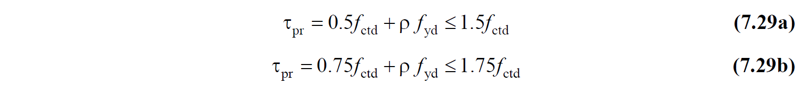
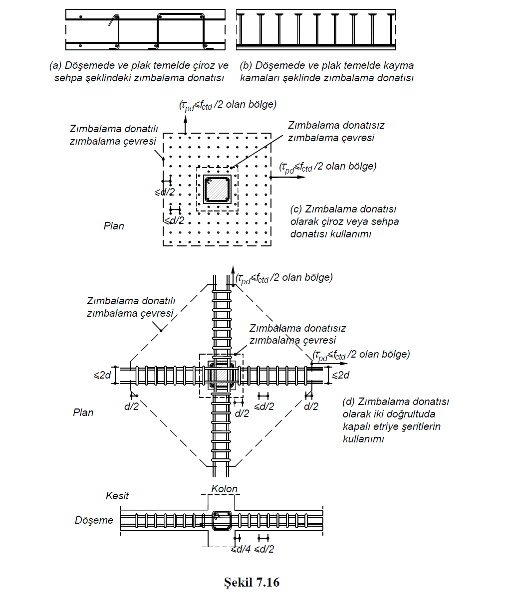
Here, ρ is the cross-sectional area of the punching weed (and / or the trestle to grasp the horizontal reinforcement) in the unit area, the punching reinforcement will be at least four pieces / m 2 , it will be placed evenly spread, starting at a maximum d / 4 distance from the column or curtain face, The distance between punching bars shall not exceed d / 2 (Figure 7.16) .
TBDY Article 7.11.12 - In cases where closed stirrup strips or sliding wedge rails are used in at least two perpendicular directions, instead of placing the punching reinforcement in a uniformly distributed manner , the punching strength of the reinforced plate in terms of shear stress Equation (7.30a) ; If sliding wedges are used, it will be calculated with Equation (7.30b) .
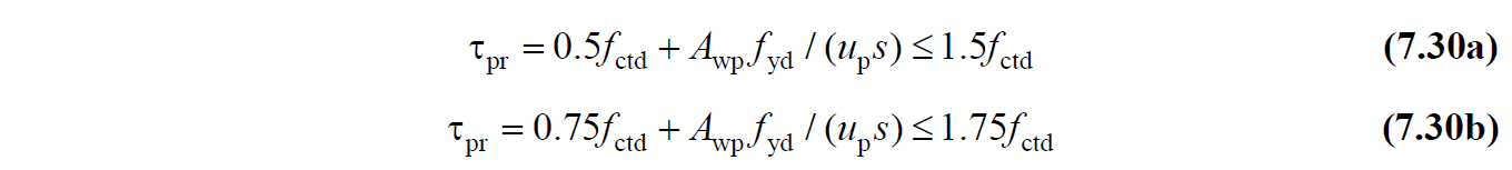
Here A wp is the total cross-sectional area of the vertical punching bars (stirrup arms or shear wedges) on the punching circumference. Punching rebars shall be placed at a maximum distance of d / 4 from the column or curtain face, the distance between stirrups or shear wedges perpendicular to the column or curtain surface shall not exceed d / 2. The distance between the stirrup arms or shear wedges parallel to the column or curtain surface shall not exceed 2d (Figure 7.16) .
TBDY Article 7.11.13 - Punching reinforcements continue to the region where the shear stress calculated at a distance d / 2 from the section where the punching reinforcement falls to f ctd / 2 , not less than four times the thickness of the slab or raft from the surface of the column or curtain . will be made.