
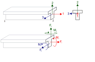
The internal forces of the rod finite elements (columns and beams) found as a result of the analysis are shown according to the local rod axis (local axis) direction assumption. A rod element analyzed in 3 dimensions has 3 local axes. These local axes may vary depending on the position and placement of the bar. An example image of local axes in frame elements is shown in the picture below.
The relationship between the numbers and colors of the local axes in frame elements is as follows.
1 direction - Red
2 direction - Green
3 direction - Blue
There are 6 freedoms in a cross section of a rod element analyzed in three dimensions. These are the translations in the directions 1,2 and 3 and rotations around 1, 2 and 3.
Direction 1 - Red indicates the axial force of the element in the direction of its axis. The force shown in the direction of axis 1 is considered as the positive direction. It also means that the force in the direction of extension of the rod is positive. On the other hand, the force in the shortening direction of the bar is considered as the negative direction. 1 In the cross section of the rod element, if the force in the direction of 1 is positive, axial tension occurs in the element, and if it is negative, axial pressure occurs. The element is indicated with "N" in the design results. "Ni" means the axial force at the i end and "Nj" means the axial force at the j end.
Direction 1 - Red , the rotation around it indicates the twisting moment of the element. The freedom of rotation around the axis 1 shown in the picture above is considered as the positive direction. The torsion moment of the element is positive if it is counterclockwise and negative torsion moment in clockwise direction, as shown in the above figure. Torsional moment is indicated by "T" in element design results. "Ti" means torsion moment at end i and "Nj" means torsion moment at j end.
2 direction - Green , the force generated in the direction of its axis is expressed as the shear force. The translational freedom indicated by 2 axis is considered as positive direction. This is also the value of the shear force in the major direction of the element. If the internal force vector in the cross section of the rod element is in the 2-axis direction as shown in the above figure, the shear force is positive, and if it is in the opposite direction of the 2-axis, the shear force is negative. In the element design results, the shear force in the 2-axis direction is shown with "V2 (maj)". "V2i (maj)" means shear force at end i and "V2j (maj)" means shear force at j end.
2 direction - Green , shown by freedom of rotation around its axis, the figure is considered to be bending moment. The freedom of rotation around the 2 axis shown in the picture above is considered as the positive direction. As shown in the figure, when the member cross section is viewed from the opposite side, if the moment around axis 2 is positive, tensile stress occurs on the left side of the section and on the right side of the section. The bending moment around the 2 axis is indicated by "M2" in the element design results. "M2i" means the bending moment at the i end and "M2j" means the bending moment at the j end.
3 direction - Blue , the force generated in the direction of its axis is expressed as the shear force. The translational freedom indicated by 3 axis is considered as positive direction. The vector of the cutting force takes positive values in the direction of the 3 axis shown in the picture above, and negative values in the opposite direction of the 3 axis. In the element design results, the shear force in the 3-axis direction is shown with "V3". "V3i" means shear force at end i and "V3j" means shear force at j end.
3 direction - Blue , the freedom of rotation around its axis is considered as the bending moment. The freedom of rotation around the 3 axis shown in the picture above is considered as the positive direction. The bending moment around the 3 axis is also called the bending moment in the major or strong axis. As shown in the figure, if the bending moment is positive, compression stress occurs in the upper part of the section and tensile stress in the lower part. The bending moment around the 3 axis is indicated by "M3 (maj)" in the element design results. "M3i (maj)" means the bending moment at the i end and "M3j (maj)" means the bending moment at the j end.
Axes and end force directions according to the local coordinate system
Beams
Looking at a beam in the plan is the axis 1 axis parallel to the beam, and the perpendicular axis 3 axis to it in the planand the vertical axis perpendicular to the working plane should be considered as the 2 axis. Left end is i, right end is j.
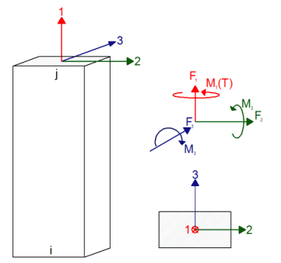
Columns and curtains
Similarly, in columns and walls, 2 axes indicating the strong direction of the column, axis 3 indicating the weak direction and vertical axis 1 axis perpendicular to the working plane should be considered. The lower end is i, the upper end is j.
In columns and beams, internal forces are either negative (-) or positive (+) according to the positive direction of the axes described above.
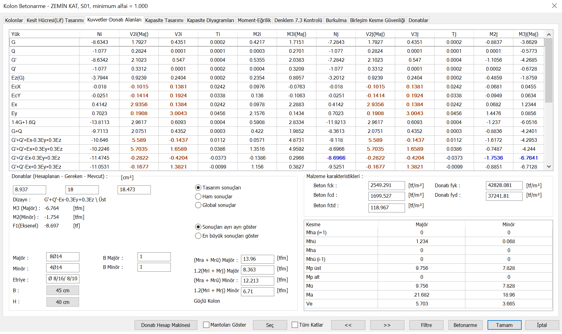
The design results of a reinforced concrete element can be seen in the picture below. The sign acceptance here is made according to the local axis of this element. At the same time, the drawings of the internal force diagrams are made according to these directions.
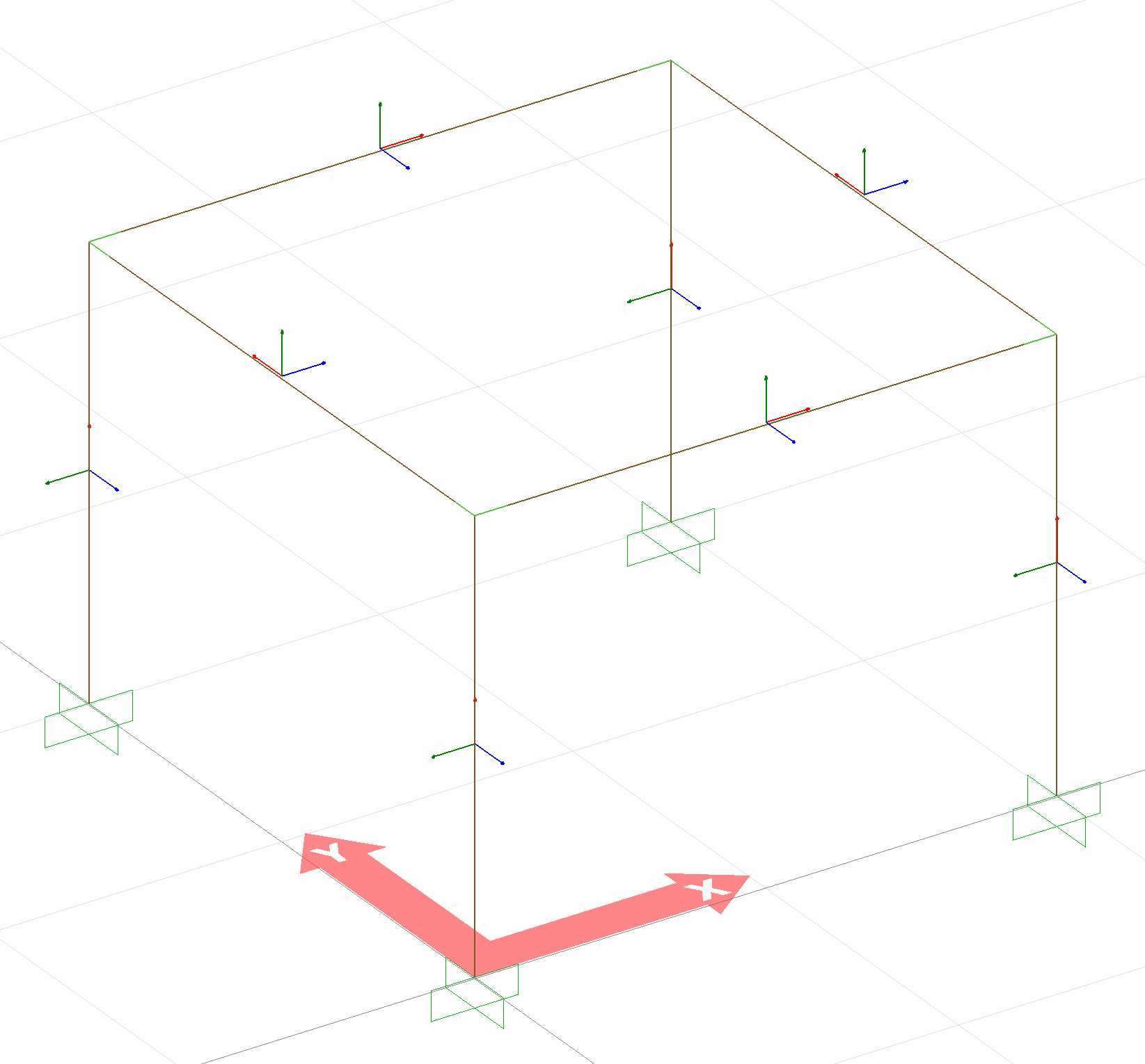
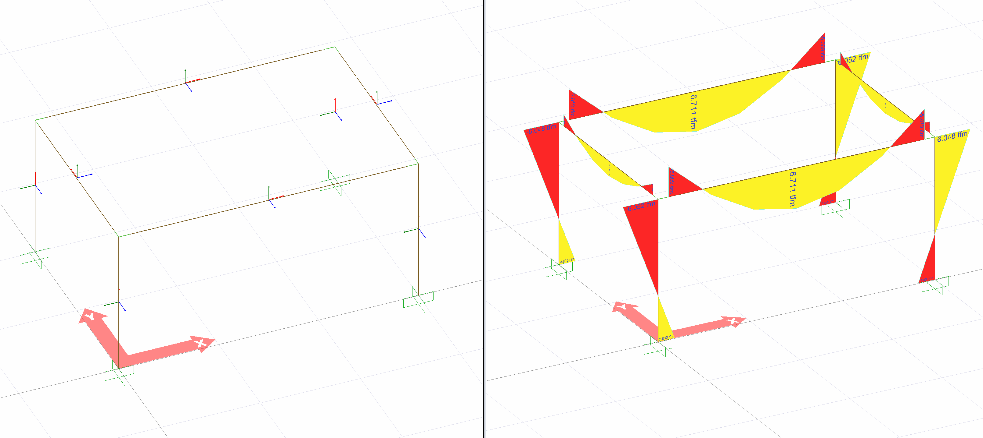
The diagram below shows the local axes and internal force [major bending moment, M3 (maj)] diagram of the elements used in the three-dimensional analysis of a simple model. According to the directional acceptance of the local axes , the forces shown in yellow are positive (+), and the internal forces shown in red are negative (-) bending moments.
Next Topic