
The support moment and support reactions of a system consisting of three rods were examined according to 3 different support collapse and compared with the results of ideCAD Structural.
Important Note: In this system solution, the effects of elongation and shear deformations are neglected for ease of manual solution. The cross-sectional area is multiplied by 10000 to neglect the elongation deformations, and the shear areas are defined as zero "0" to neglect the shear deformations.
|
Loading Status |
Controlled internal force |
ideCAD Static |
Manual solution |
Percentage of error |
|---|---|---|---|---|
|
|
N (chicken) |
-6.293 |
-6.293 |
0% |
|
M (chicken-in) |
906.250 |
906.250 |
0% |
|
|
|
N (chicken) |
-1.115 |
-1.115 |
0% |
|
M (chicken-in) |
160.492 |
160.492 |
0% |
|
|
|
N (chicken) |
18.125 |
18.125 |
0% |
|
M (chicken-in) |
-2610 |
-2610 |
0% |
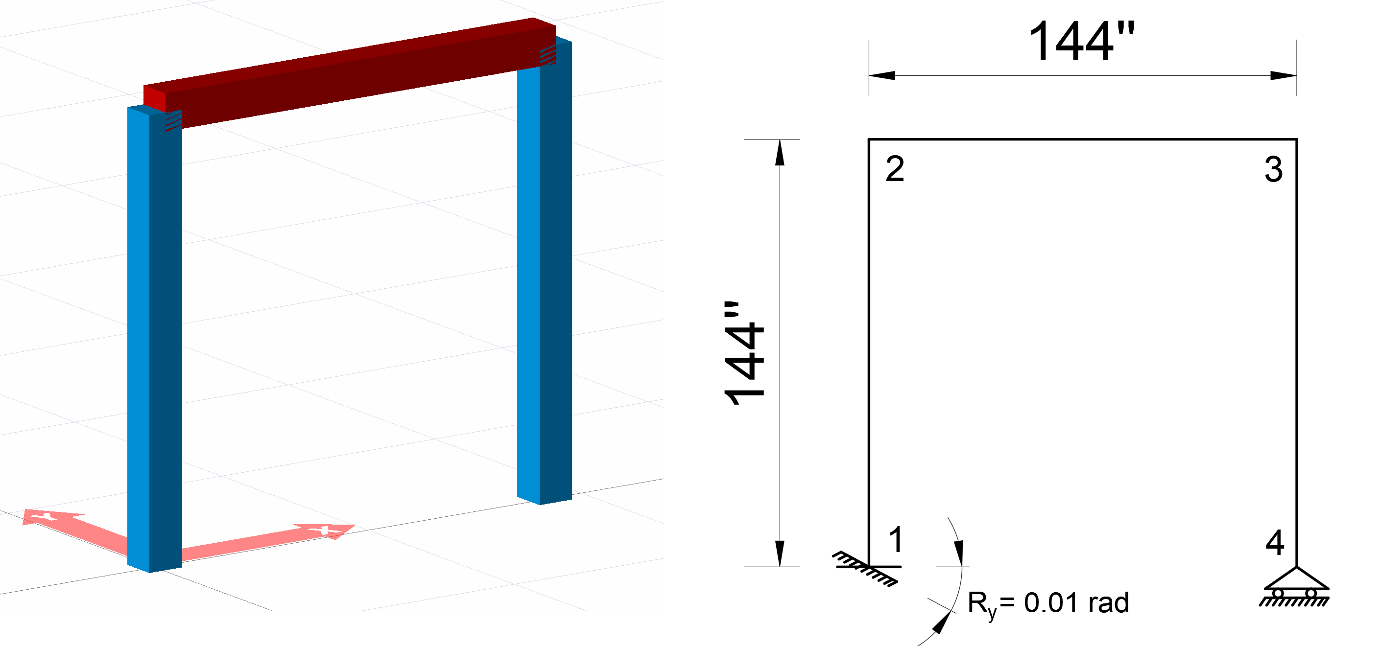
Geometric Properties and System Description
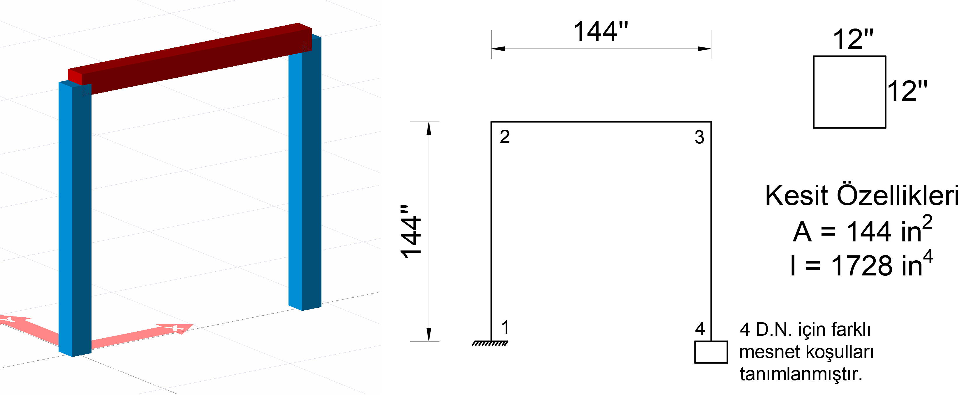
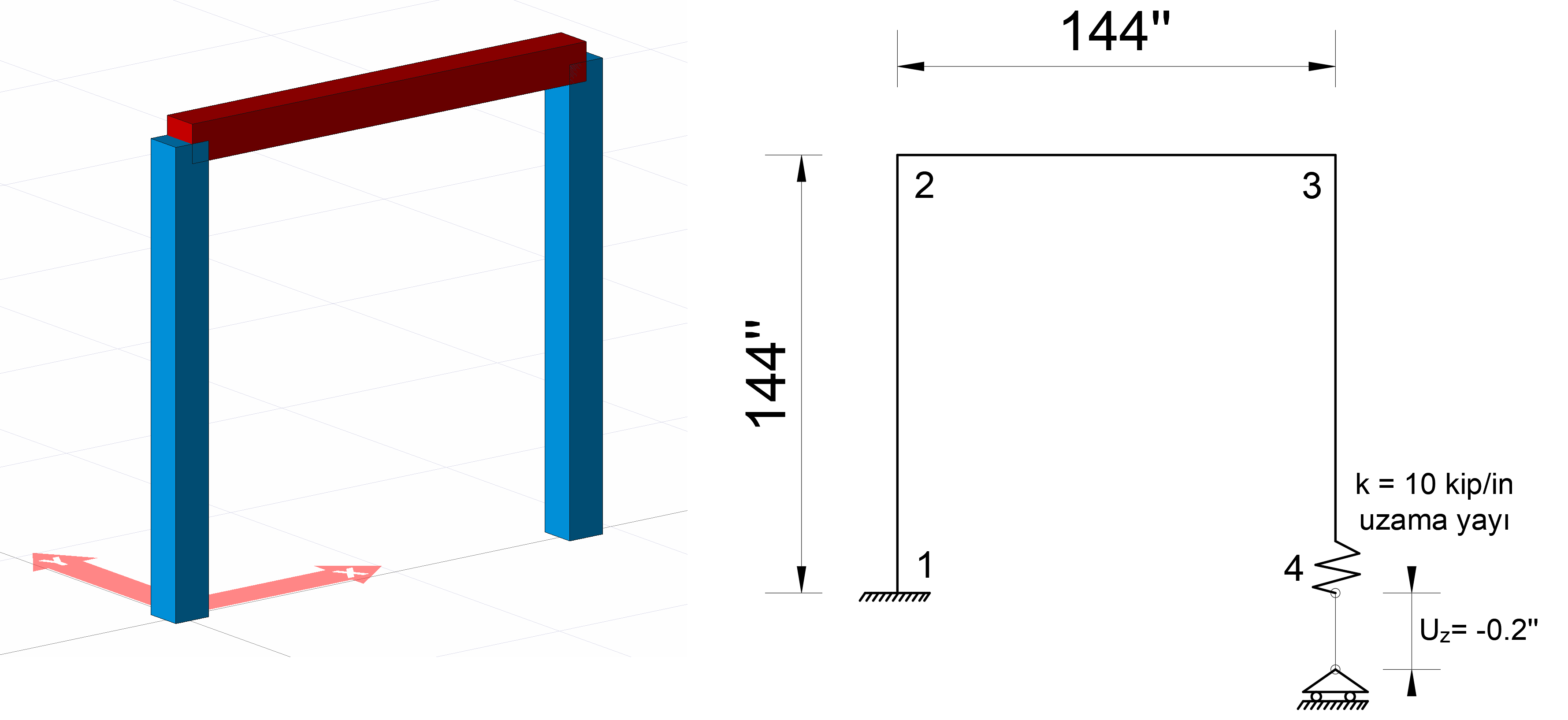
In the picture above, a system consisting of three rod elements is given. The lengths of all bars are defined as 144 inches. From 4 joints, joint 1 is defined as a built-in support, and joints 2 and 3 are freely defined. For joint 4, different support conditions will be created for three cases.
A square section with a side of 12 inches is used as a rod element.
The area of the square section is calculated as A = 12 * 12 = 144 in 2 and the
moment of inertia I = (1/12) * (12 * 12 3 ) = 1728 in 4
.
The modulus of elasticity of the material used is taken into consideration as E = 29000 k / in 2 .
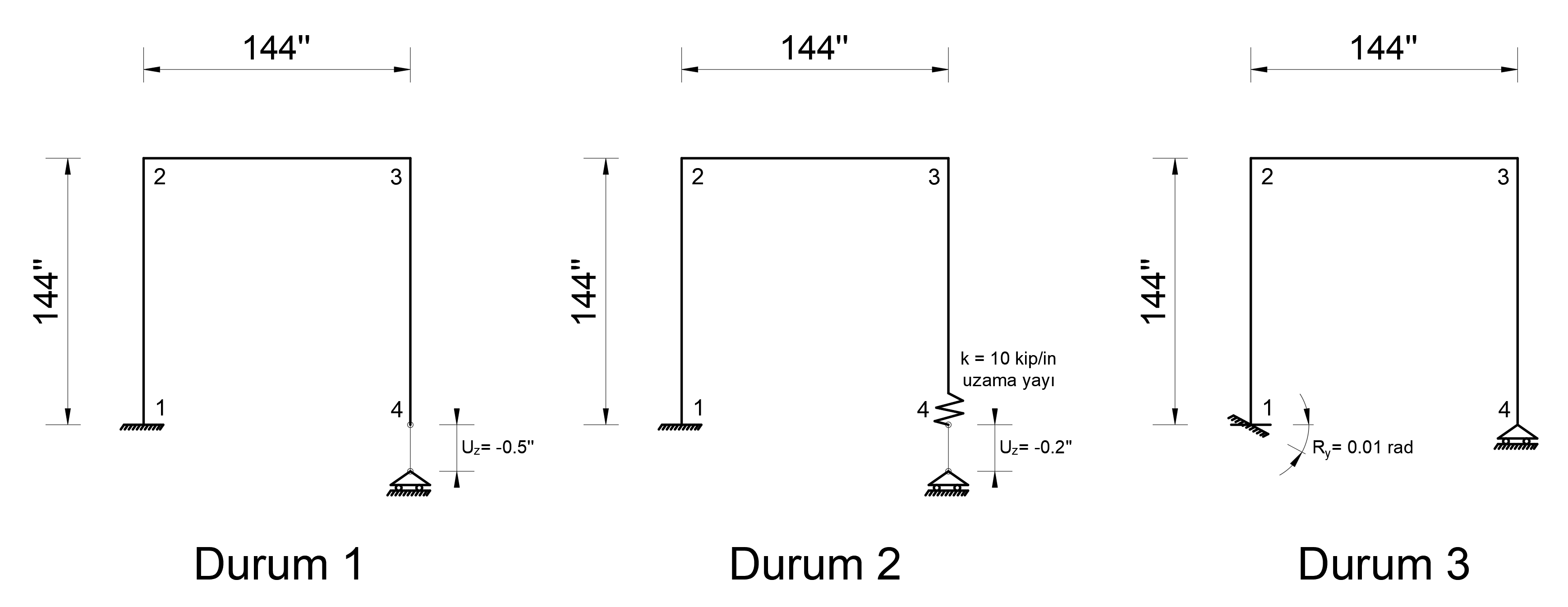
Loading Cases
In the above system, 3 loading cases are defined below. These loading states are named as State1, State2 and State3. Virtual Work Method was used to find the internal force and support reactions caused by the support collapses .
You can find the files with defined loading status below.
Durum_1_mesnet_çökmesi.rarDurum_2_mesnet_çökmesi.rarDurum_3_mesnet_çökmesi.rar
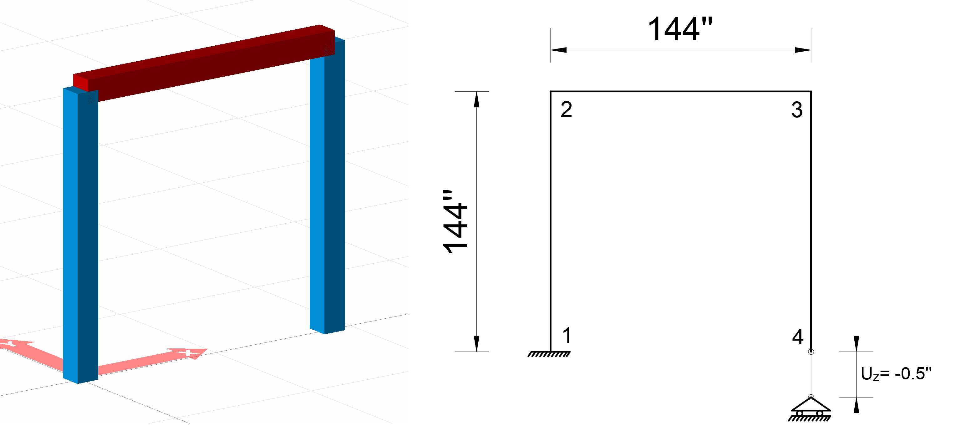
Condition 1
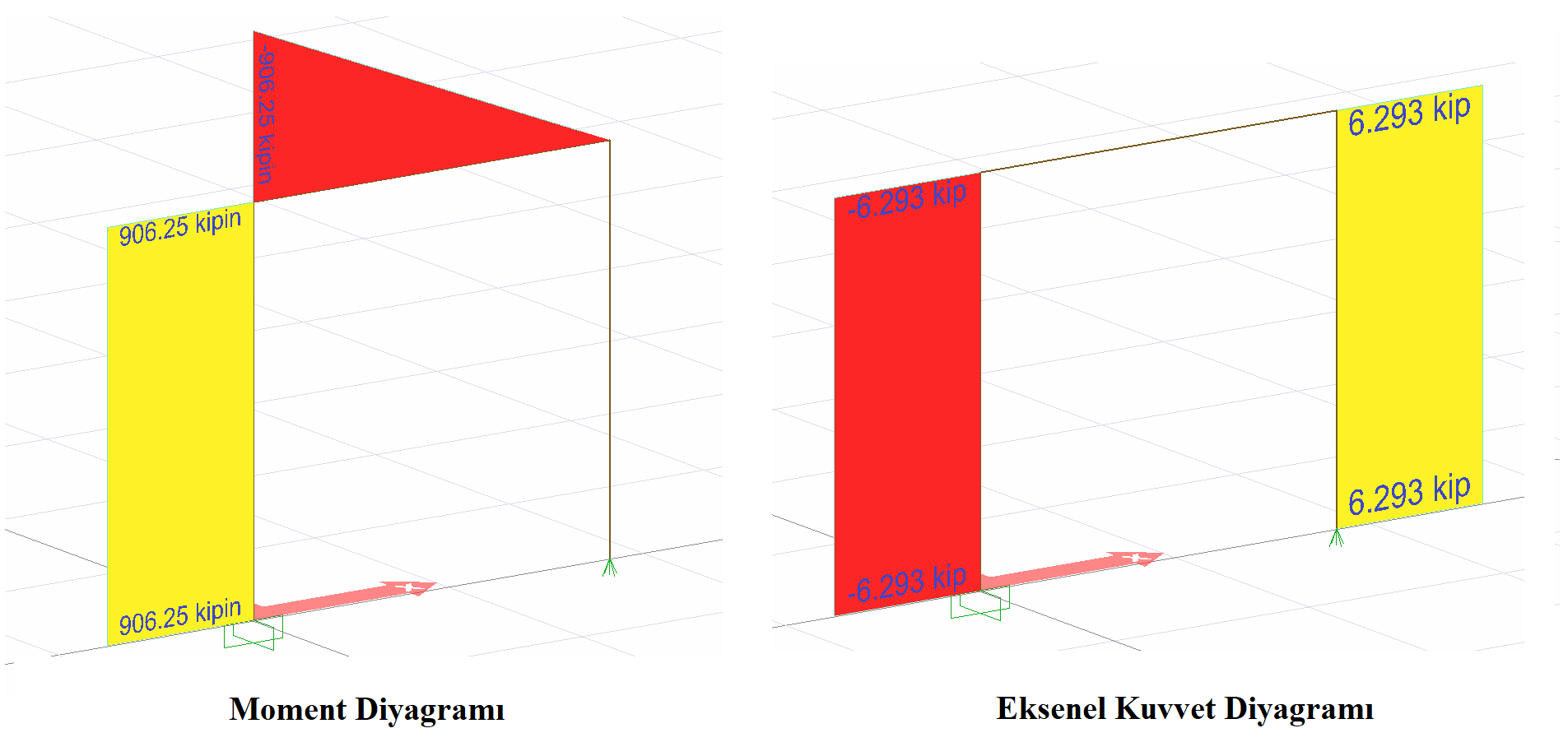
For “Case 1” loading, a sliding bearing is defined at joint 4 and a 0.5 in support collapse in the opposite direction of the Z axis is defined (UZ = -0.5 ''). There is no external load in the system. For case 1, the support reactions and the moment diagram at joint 1 will be compared with the hand solution.
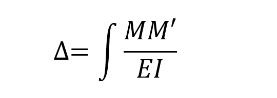
Virtual Work Method was used to find the internal force and support reactions caused by the support collapses . In the virtual work method, the moment diagram with unit loading, M 'and the moment diagram formed due to the normal loading of the system can be found by using the integral given below. In virtual work method, the following integral should be taken separately for all rods and its sign should be determined considering the moment direction.
Here, as the first step, the movement of the movable support in the Z direction at the joint number 4 is removed and a 1 unit of force is applied in the UZ direction and the function of this moment diagram connected to the x of this moment diagram is calculated as follows.
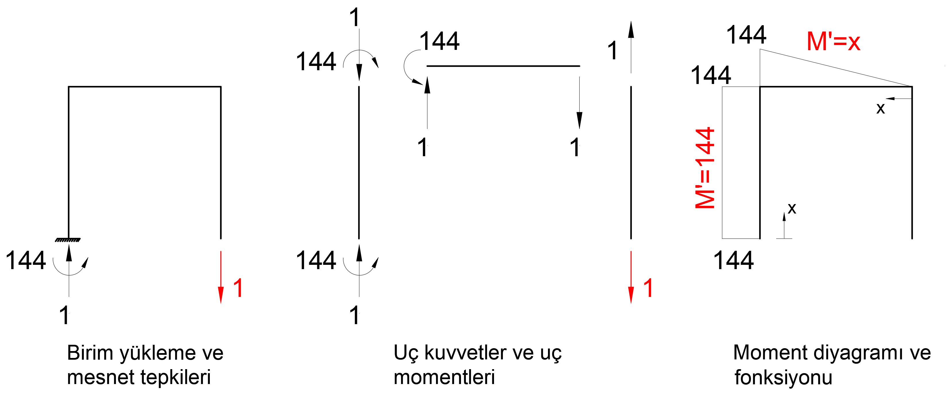
M 'moment diagram above is the moment diagram due to unit loading. Besides, to find the M moment diagram, the function of the moment diagram consisting of external loading must be calculated. However, since the loading situation is not external load but support collapse, the unit will form the same moment diagram as the loading. Here, the deformation of the system is found by accepting the support reaction of the joint number 4 as unit load. In other words, the deformation caused by one unit of loading is calculated. Then, the coefficient that will make this deformation value of 0.5, that is, the collapse value of the support, is found. With this coefficient, when the moment diagram found from unit loading and the support reactions are multiplied, the moment diagram and support reactions resulting from the support collapse are found.
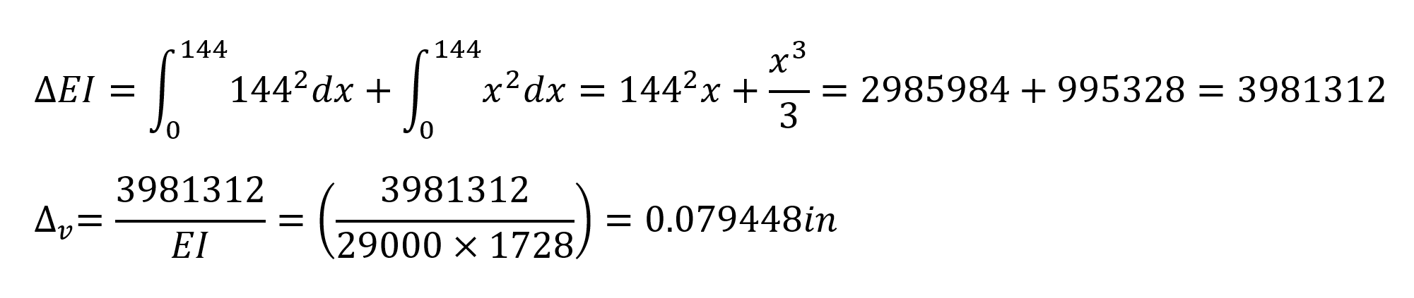
Under these conditions, the strain that will occur when 1 unit of force is applied at 4 joints is calculated as follows.
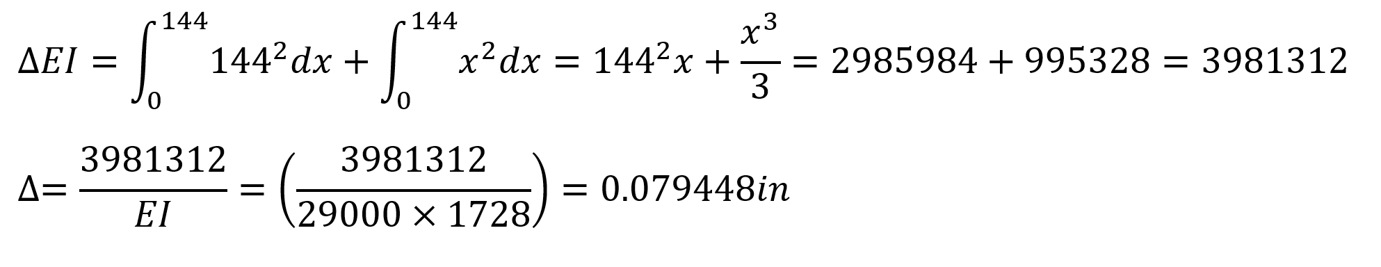
In this equation, unit represents the deformation at the point and direction of loading. In this case, the deformation obtained when 1 unit is loaded on joint 4 is calculated as = 0.079448 in. The force required for a 0.5 in support collapse of joint 4;
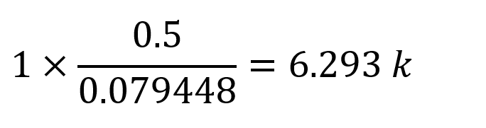
found as. Under these conditions, support reactions and moment diagram can be plotted as follows.
The moment value is calculated as 144 * 6.293403 = 906.2500 kip-in.
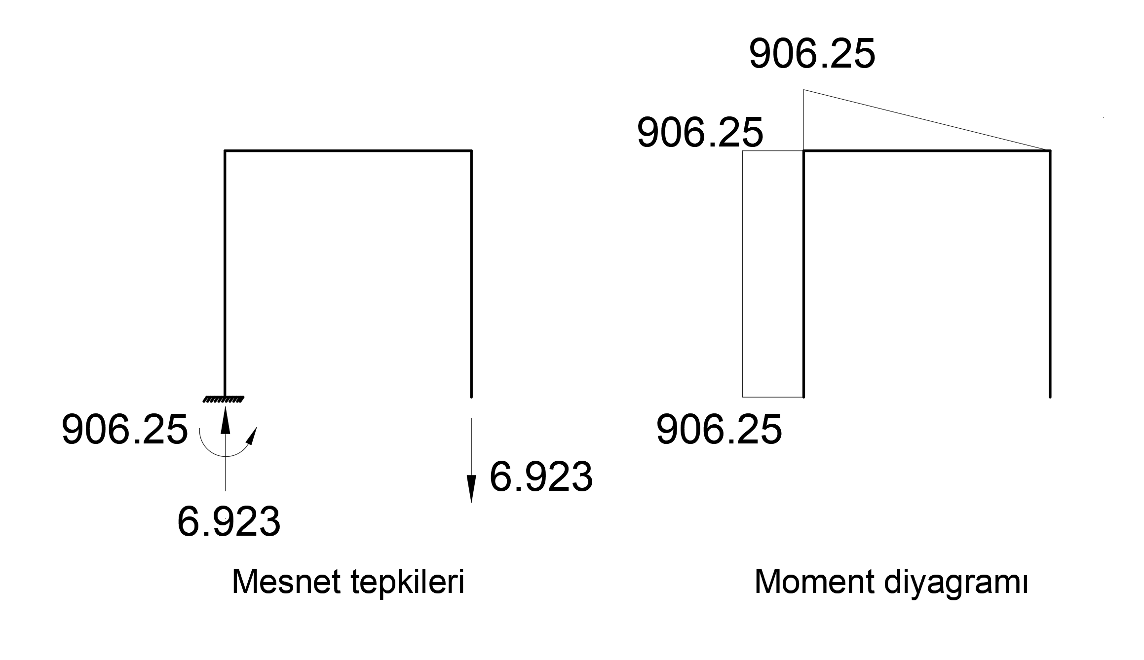
M = 906.25 kip-in and support response N = 6.923 kip. This result is exactly the same with ideCAD Structural.
Condition 2
For “Case 2” loading, a sliding bearing is defined at joint 4 and a support collapse of 0.2 inches in the opposite direction of the Z axis is defined (UZ = -0.2 ''). A spring with stiffness k = 10 kip / in is defined at the end of the element located at 4 joints between 3-4 joints. There is no external load in the system. For case 2, the support reactions and moment diagram at joint 1 will be compared with the hand solution.
Virtual Work Method was used to find the internal force and support reactions caused by the support collapses . In the virtual work method, the moment diagram with unit loading, M 'and the moment diagram formed due to the normal loading of the system can be found by using the integral given below. In virtual work method, the following integral should be taken separately for all rods and its sign should be determined considering the moment direction.
Here, as the first step, the movement of the movable support in the Z direction at the joint number 4 is removed and a 1 unit of force is applied in the UZ direction and the function of this moment diagram connected to the x of this moment diagram is calculated as follows.

The addition of a spring with the stiffness of k = 10 kip / in to 4 joints results in the calculation of another displacement value in addition to the support collapse made by Case 1. In this case , two different terms Δ v and değeri y can be written for the displacement value calculated at this point .
Δ v is the value of displacement at joint 4 resulting from unit loading resulting from removal of the bracket and spring. Virtual Work Method using Δ there is value calculated as Case 1 is calculated.
Değeri y value is the elongation value of the spring with stiffness k = 10 kip / in due to unit loading at joint 4. Elongation value for 1 unit of loading;
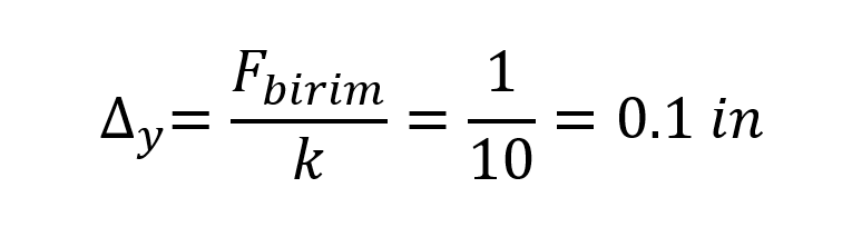
will be. In this case, the elongation value of joint 4 from the unit loading;

found as. In this case, the deformation obtained when 1 unit is loaded on joint 4 is calculated as Δ = 0.179448 in. The force required for a 0.2 in support collapse of joint 4;
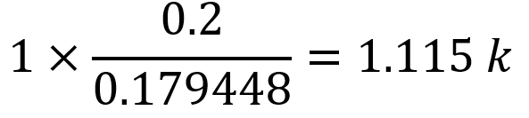
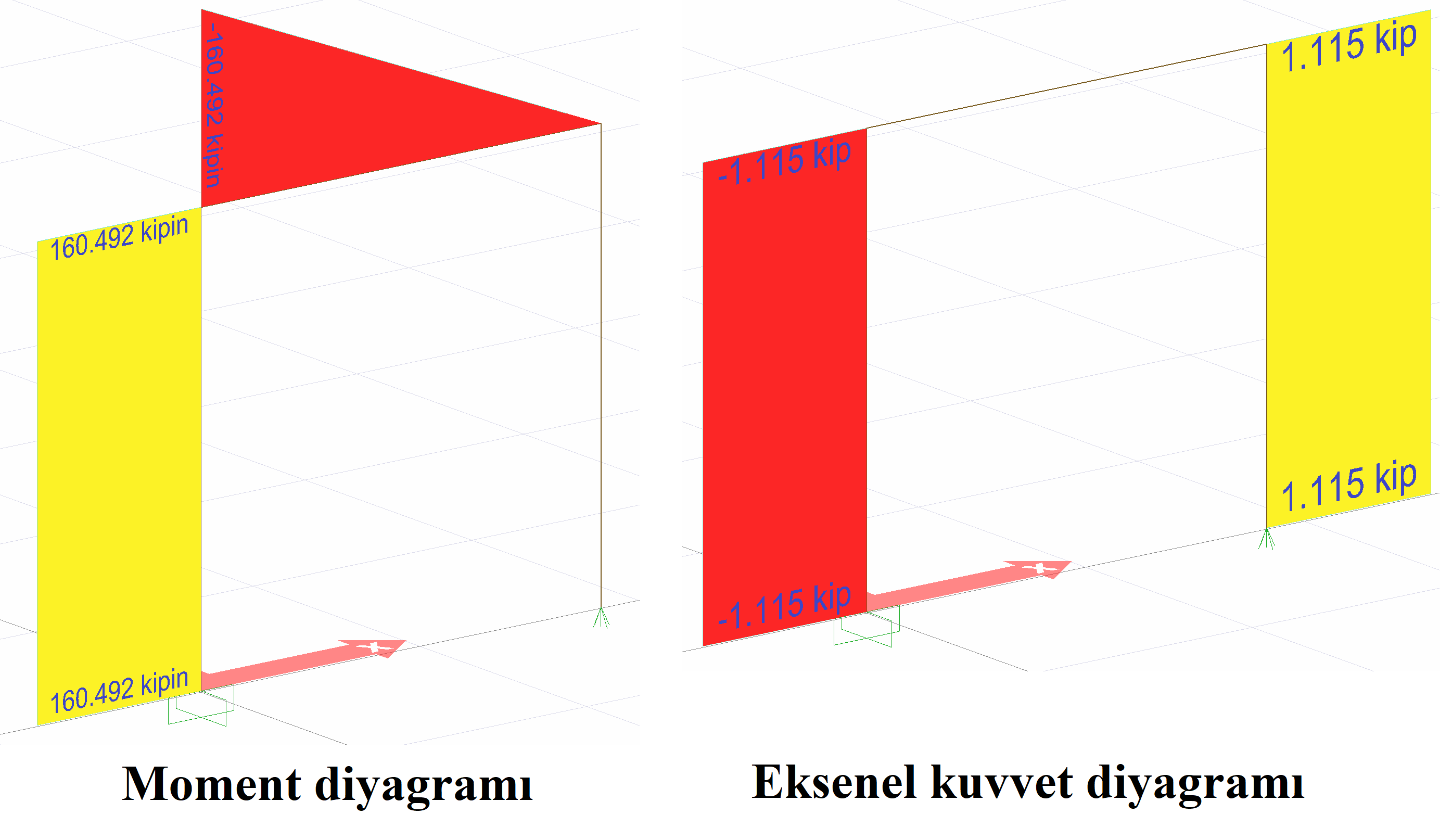
found as. Under these conditions, support reactions and moment diagram can be plotted as follows.
The moment value is calculated as 144 * 1.114529 = 160.492 kip-in.
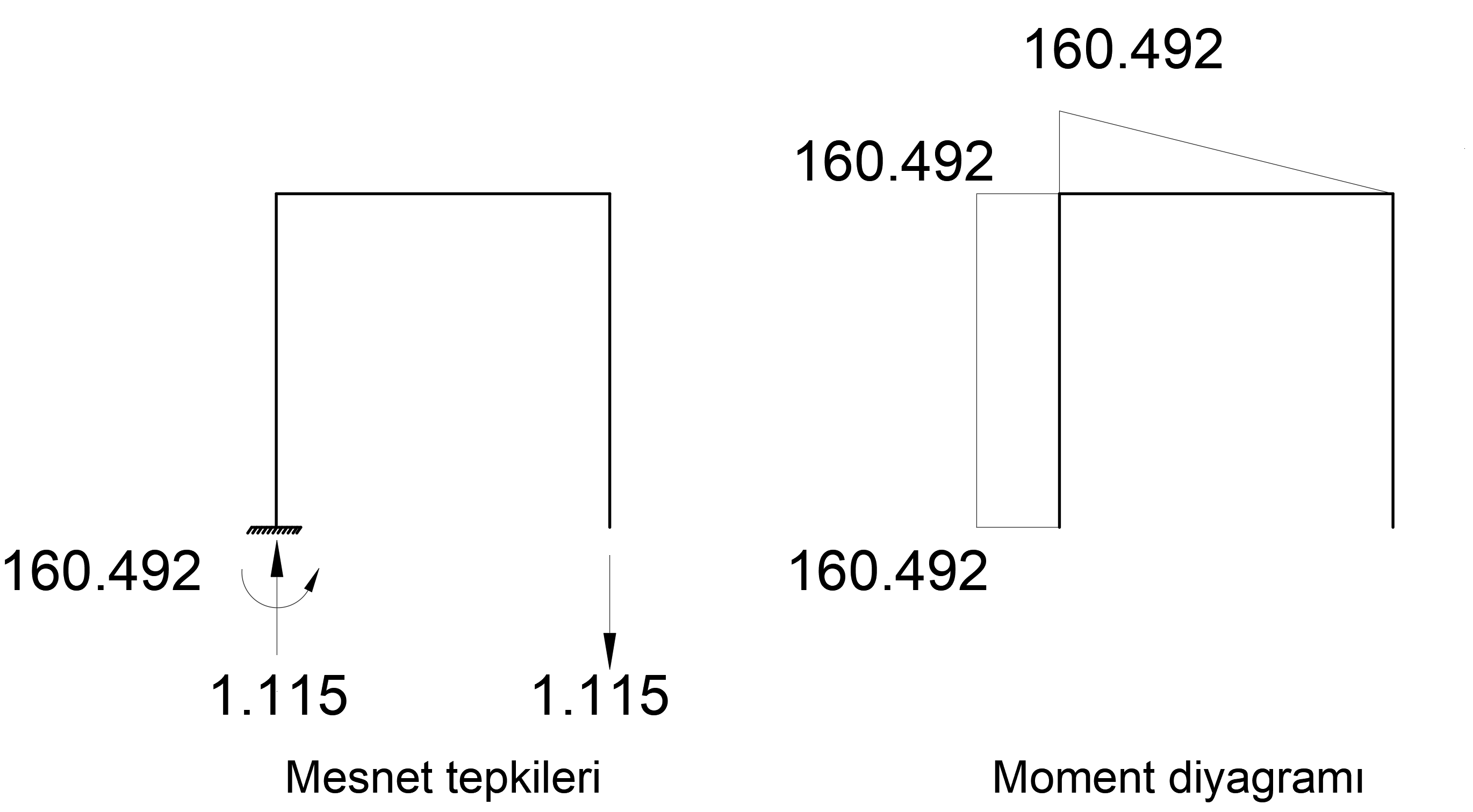
M = 160,492 kip-in and support response N = 1,115 kip. This result is exactly the same with ideCAD Structural.
Condition 3
A sliding bearing is defined at joint 4 for a "case 3" loading. A support collapse of 0.01 rad rotation around the Y axis is defined at joint 1 (RY = 0.01 rad). There is no external load in the system. For case 3, the support reactions and moment diagram at joint 1 will be compared with the hand solution.
Virtual Work Method was used to find the internal force and support reactions caused by the support collapses . In the virtual work method, the moment diagram with unit loading, M 'and the moment diagram formed due to the normal loading of the system can be found by using the integral given below. In virtual work method, the following integral should be taken separately for all rods and its sign should be determined considering the moment direction.
Here, as the first step, the rotational stiffness of the built-in support at joint number 1 is removed around the Y axis and 1 unit moment is applied in the RY direction and the function of this moment diagram is calculated as follows with the M 'moment diagram.
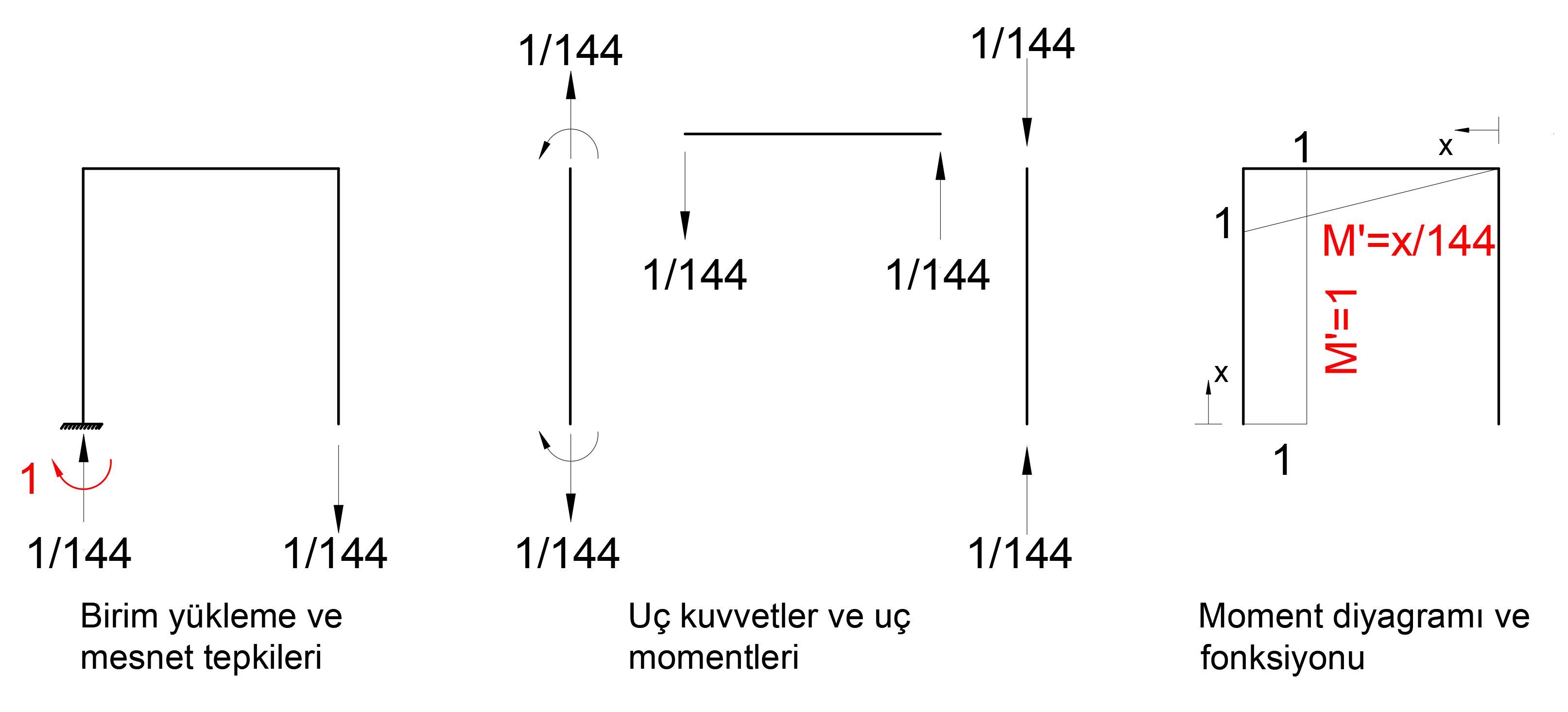
M 'moment diagram above is the moment diagram due to unit loading. In addition, to find the M moment diagram, the function of the moment diagram consisting of external loading must be calculated. However, since the loading situation is not external load but support collapse, the unit will form the same moment diagram as the loading. Here, the deformation of the system is found by accepting the support reaction of the joint number 1 as unit load. In other words, the deformation caused by one unit of loading is calculated. Then, the coefficient that will make this deformation value is 0.01 rad, that is, the support collapse value. With this coefficient, when the moment diagram found from unit loading and the support reactions are multiplied, the moment diagram and support reactions resulting from the support collapse are found.
Under these conditions, the strain that will occur when 1 unit of moment is applied at 1 joint is calculated as follows.
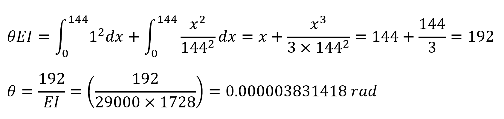
In this equation, unit represents the deformation at the point and direction of loading. In this case, the deformation obtained when 1 unit of torque is loaded on the numbered joint is calculated as θ = 0.000003831418 rad. The moment required for joint 1 to collapse at 0.01 rad;
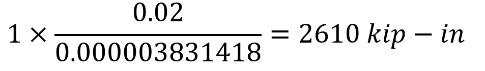
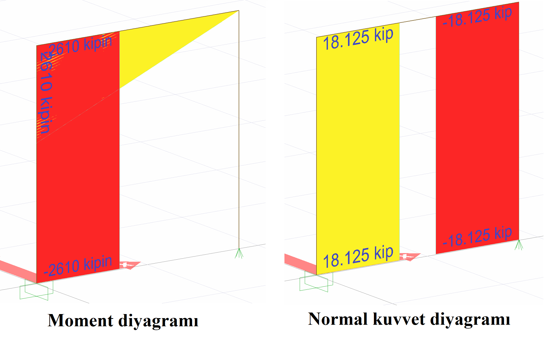
found as. Under these conditions, support reactions and moment diagram can be plotted as follows.
Normal force value is calculated as (1/144) * 2610 = 18.125 modes.
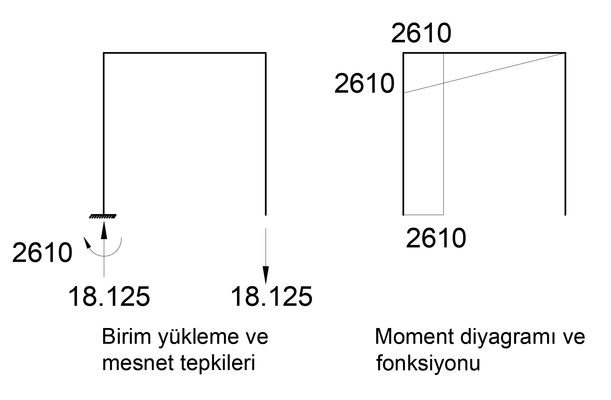
M = 2610 kip-in and support response N = 18,125 kip. This result is exactly the same with ideCAD Structural.
Next Topic