
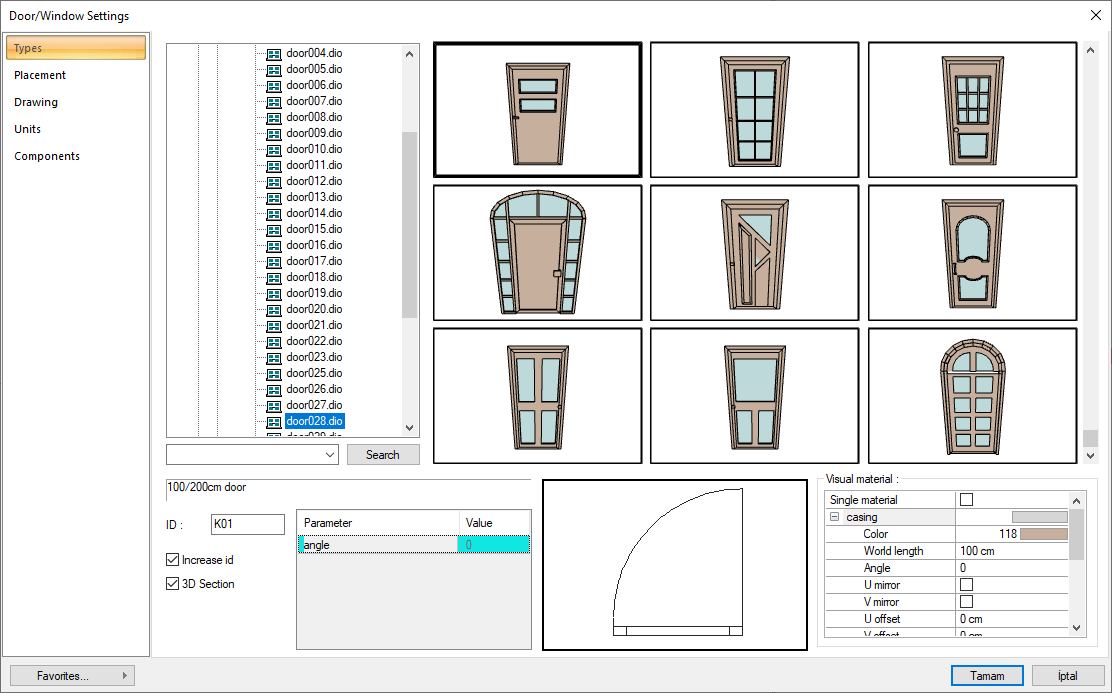
Door-window types are listed in the Door/Window Settings dialog. Settings such as width, height, elevation, label properties of the door/window are included in this dialog. Before or after creating the door/window, the settings dialog is opened and the settings are arranged in line with the architectural or structural project design.
Location of Door/Window Settings Dialog
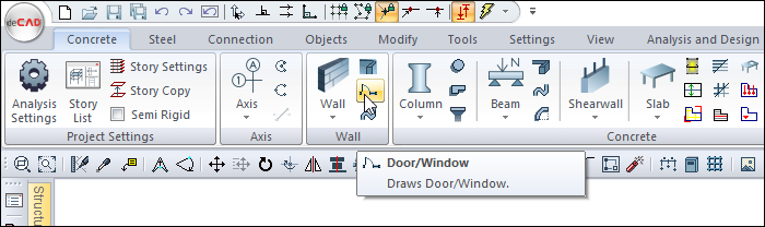
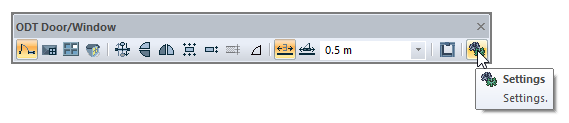
The ODT Door/Window command that appears after the Door/Window command is run is available in the auxiliary toolbar.
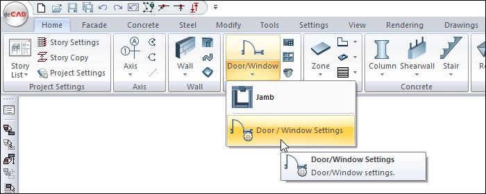
You can also access the ideCAD architectural under the Home menu, Door/Window title.
Types Tab
|
Specifications |
|---|
|
Type list 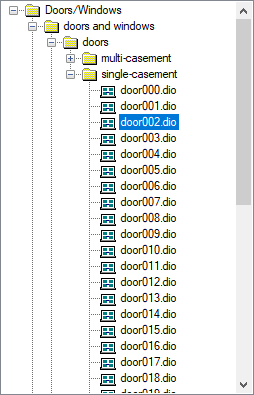
Doors and windows are divided into folders according to their types. If the + signs next to the folder icons are clicked with the left mouse button, sub-folders and door / window files are displayed. A selection is made by clicking on the door window files with the left mouse button. |
|
3D type images 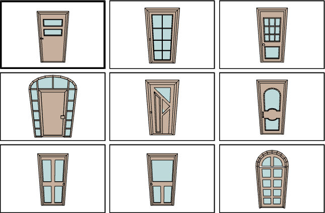
There are three dimensional images of the type list. If the mouse is moved while holding down the left mouse button, the object will be rotated. If the mouse is moved by clicking the right mouse button, the object can be zoomed in and out. In this way, it is possible to examine the door/window in three dimensions. Selection is made by clicking on the door/window image with the left mouse button. |
|
Search Provides easy access by entering the door/window name in the door/window list. |
|
Design dimensions The original design dimensions of the selected door / window appear. Dimensions cannot be changed from this line. |
|
ID Enter a name for the door/window object to be placed in the ID box. |
|
3D section If the box is marked, the openings of the doors/windows are also taken into account in the sections to be taken, and the doors/windows are displayed in this way in the sections. |
|
Parameter 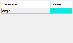
The opening parameters of the selected door/window (if any) are listed here. The opening angle of the door/window or the opening distance for sliding and guillotine doors/windows can be adjusted by changing the value in the value digit opposite the relevant parameter. Angle values are degrees and distance values are meters. Negative or positive value can be entered. |
|
Plan representation 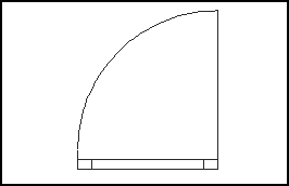
The plan view of the selected door/window appears. |
|
Visual material 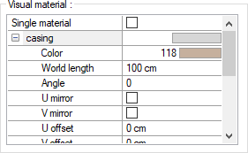
The material to be used on the front, back and other surfaces of the wall is selected from the list. Surfaces are covered with the selected material and displayed as such in renderings. Texture length is entered into the world length. For example; If 1 is entered, the selected material texture is taken as 1 meter and covered on the relevant walls. In the angle, the angle of the texture is entered. Touch the U and V offset. The motion value in the x and y plane is entered. With U and V mirroring, the texture is symmetrical with respect to the y and x planes. By selecting the single material option, the material selected in "Front material" is used on all surfaces of the wall. |
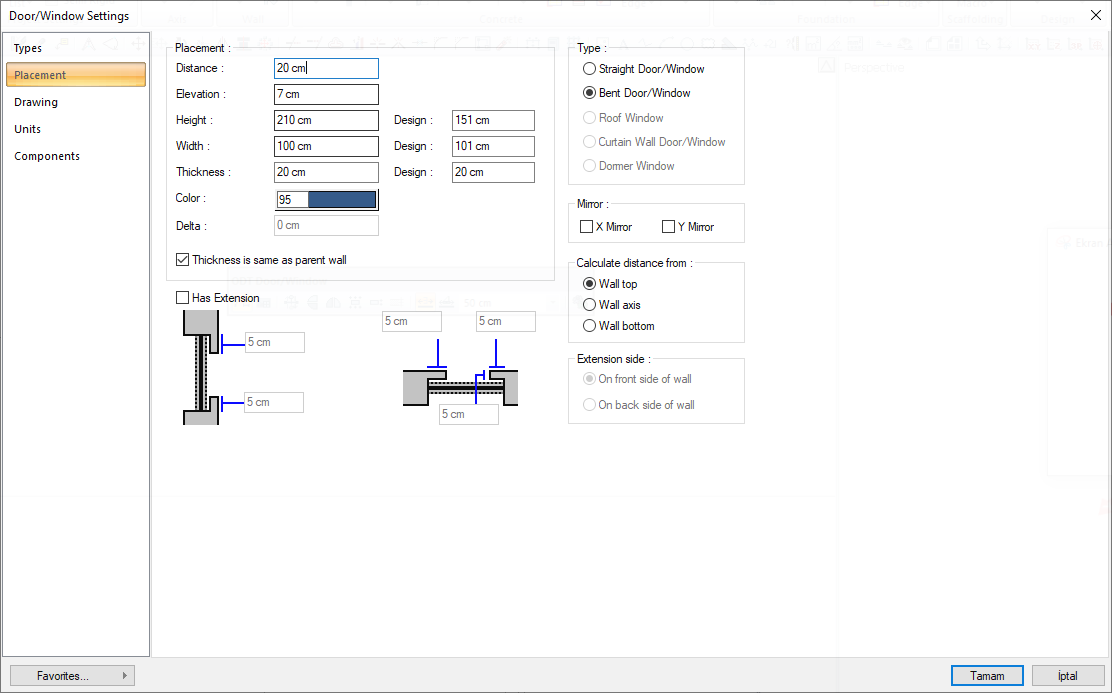
Placement Tab
|
Specifications |
|---|
|
Distance It determines the reference distance when placing the door and window. For example, if clicked near the left end of the wall, it is the distance between the left end point of the wall and the left end point of the door/window. |
|
Elevation The level of the door/window base is entered in relation to the wall base. For example, if you enter 50 cm, the height of the door/window from the base of the wall will be 50 cm. |
|
Height Door/window height is entered. The height used during the design is given in the design section. While changing the size, the ratios of the design values should not be exceeded, as this may cause unwanted deformations. |
|
Width Door/window width is entered. The width used during design is given in the design section. While changing the size, the ratios of the design values should not be exceeded, as this may cause unwanted deformations. |
|
Thickness Door/window thickness is entered. The thickness used during the design is given in the design section. While changing the size, the ratios of the design values should not be exceeded, as this may cause unwanted deformations. |
|
Color It is the drawing color of the door/window. When the color box is clicked, the appropriate color is selected from the window that opens. |
|
Delta It determines the distance of the door/window to the wall center axis. If the value is zero, the door/window is on the middle wall axis. Positive value shifts the door / window from the wall center axis upwards, negative value downwards (with respect to the viewing direction). |
|
Thickness is same as parent wall By checking the box, whatever the design thickness of the selected door/window is, the door window thickness will be the thickness of the wall on which it is placed. |
|
Has extension 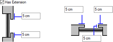
When the door/window is placed, it is marked if the wall will be toothed outward. According to the plan view (right schematic drawing) the descriptions of the parameters are: Top left line: In this line, the information about how long the wall piece will be left from the left of the door / window to the right inside the window is entered. Top right line: In this line, the information about how long the wall piece will be left from the right of the door / window to the left of the window is entered. Middle line: In this line, the information about how long the wall piece will be left from the top of the door / window towards the bottom of the window is entered. This value can only be used for rectangular doors / windows. Change can be viewed in perspective. The explanations of the parameters according to the section view (left schematic drawing) are as follows: Bottom line: In this line, the information about how long the wall piece will be left from the bottom of the door / window towards the top of the window is entered. This value can only be used for rectangular doors / windows. Change can be viewed in perspective. Top line: In this line, the information about how long the wall piece will be left from the top of the door / window towards the bottom of the window is entered. This value can only be used for rectangular doors / windows. Change can be viewed in perspective. |
|
Extension side 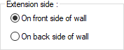
When overflow is marked, overflow direction becomes active. It determines that the overflow will be over the wall according to the plan image, and the overflow will be made under the wall if it is under the wall. |
|
Type 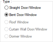
Includes the type of door / window installed. Only straight door / window and curved door / window selections can be made. Other choices will be passive. Straight door/window: Determines whether the door/window placed on the curvilinear wall will be flat or in the form of the wall on which it is located. If the "Straight Door/Window" option is selected, the door and window are placed on the curved wall with a straight form. Bent door/window: It determines whether the door/window placed on the curvilinear wall will be stright or in the form of the wall on which it is located. If the "Bent Door/Window" option is checked, the door/window takes the form of the curved wall on which it is located. Roof window : It is understood here whether the window used is a skylight or not. It is not allowed to change this option in the dialog. When the "Sky Window" command is clicked from the toolbar that opens when the door / window command is run, the selected door / window is the skylight. If the Door / Window dialog is entered while in "Roof Window" mode, this option appears checked. " Curtain wall door / window: It is understood here whether the window used is a curtain wall door / window. It is not allowed to change this option in the dialog. When the window / door command is run, when the "Curtain Wall Door / Window" icon is clicked from the opened toolbar, the selected door / window is the curtain wall door / window. Domer window: It is understood here whether the window used is an eyelet window or not. It is not allowed to change this option in the dialog. When the "Eyelet Window" icon is clicked from the toolbar that opens when the door / window command is run, the selected window is the eyelet window. |
|
Mirror With X mirror, it changes the opening direction of the door/window relative to the wall axis. With Y mirror, it changes the opening direction of the door/window relative to the axis perpendicular to the wall axis. |
|
Calculate distance from 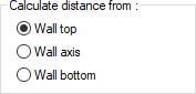
When placing the door/window at the current point of the wall joint, it is determined where the reference distance will be taken from the wall. Wall top: Place the door/window at the end of the wall (1st wall) and create a second wall away from the end of the wall (2nd wall). When this option is checked, the door / window will be placed on the 1st wall, while the distance from the end of the wall will be used based on the top of the 2nd wall according to the viewing direction. Wall bottom: Place the door/window at the end of the wall (1st wall) and create a second wall away from the end of the wall (2nd wall). When this option is selected, the door / window will be placed on the 1st wall, based on the distance from the end of the wall, based on the bottom of the 2nd wall according to the viewing direction. Wall axis: The door/window is placed at the end of the wall (1st wall) and a second wall is created at the end of the wall in another direction (2nd wall). When this option is selected, the door / window will be placed on the 1st wall, while the distance from the end of the wall will be used based on the middle axis of the 2nd wall. |
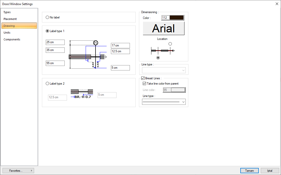
Drawing Tab
|
Specifications |
|---|
|
No label It is marked if the naming and dimensioning shown on the door window is not wanted. |
|
Label type 1 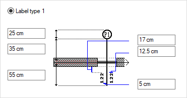
Madiran standard measurement used in Most codes. Door/window dimensioning line dimensions and text placements are adjusted by entering the wanted values in the relevant boxes on the figure. |
|
Label type 2 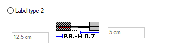
Label 2 is regulated for overseas standards. Door/window dimensioning line dimensions and text placements are adjusted by entering the wanted values in the relevant boxes on the figure. |
|
Dimensioning 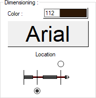
Sets the color of dimension text. When the color box is clicked, the appropriate color is selected from the window that opens. When the button just below this parameter is clicked, the "Font Settings" dialog appears. Font of information text can be set here. The wanted dimensioning direction on the shape is selected with the location. The scaling balloon is located on the side marked according to the viewing direction. |
|
Breast lines 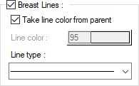
After the door/window is placed, the trace of the wall under it is marked, if desired, in the drawings. The color and type of the line is selected. If desired, the color can be made the same as the wall color. |
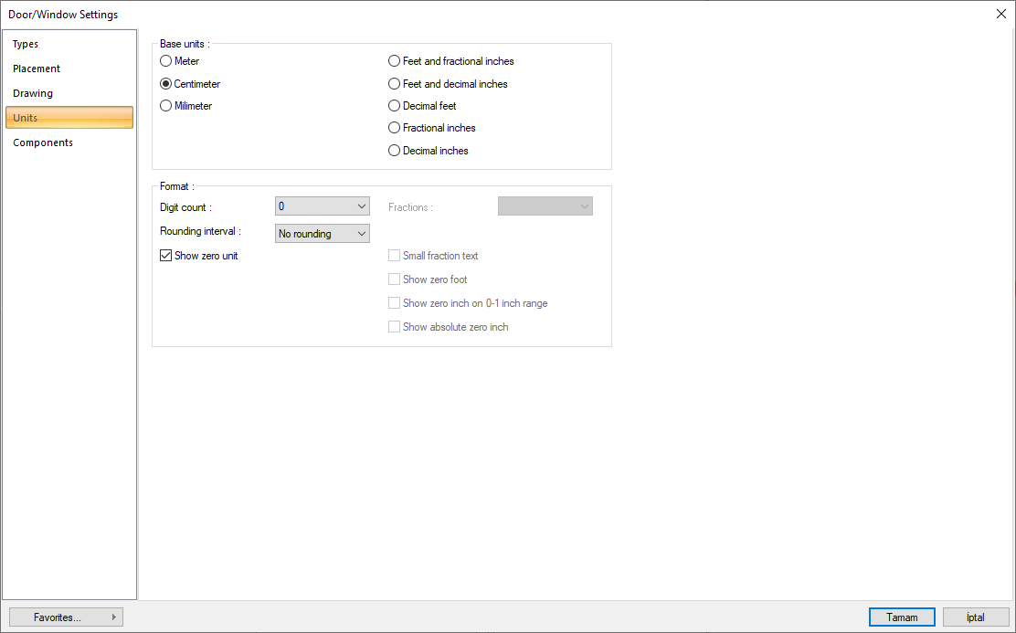
Units Tab
|
Specifications |
|---|
|
Basic units 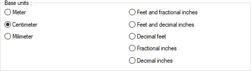
One of the selections is activated by clicking the left mouse button on the job. Meter : If checked, the unit of information text will be meters.
|
|
Digit count 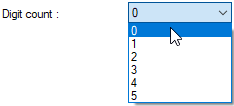
It determines how many digits will be shown after the comma. The desired number is selected from the list. For example, if 2 is selected, units will be shown as two digits after the comma. If 0 is selected, units will not be shown after the comma. |
|
Fractions 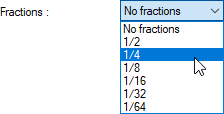
It determines the precision of the dimension to be made in fractional inch format. In the list, there are options with a sensitivity of 1/2, ¼, 1/8, 1/16, 1/32, 1/34. If "no fraction" is selected, units will appear without fractions. |
|
Rounding interval 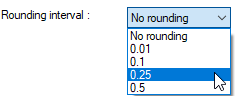
It determines the rounding range of the measurement to be made in meters, centimeters or millimeters. If No rounding is selected, the dimensioning is done at exact value. As the range gets larger, the dimensioning is rounded up to the selected range. |
|
Show zero unit If it is not checked, it does not show the zero and point on the left in dimensioning. For example, it measures 0.20 as 20. If marked, the value 0.20 is scaled as 0.20. |
|
Small fraction text When fractional inch format is selected, determines the fractional part to display in upper / lower case. If it is checked, the fraction is slightly above the integer and small, if not, the fraction is shown the same size next to the integer. |
|
Show zero foot Determines whether 0 is displayed in the 0-foot gauge (less than 1 foot gauge). For example, if it is not checked, it will show a measure of 0 '- 15 "as -15". If marked, it shows as 0'-15 ". |
|
Show zero inch on 0-1 inch range For example, a dimension inch with a value of 8'-0 1/6 "is in the range 0-1. If the option is not ticked, the value 8'-0 1/6" will be displayed as 8'-. In other words, inch values in the 0-1 range will not be displayed. |
|
Show absolute zero inch Determines whether to show zero inches in the dimension value where inches is absolute zero. For example, a dimension of exactly 10 'will be displayed as 10'-0 "if this option is selected. If not checked, it will be displayed as 10" -. |
Components Tab
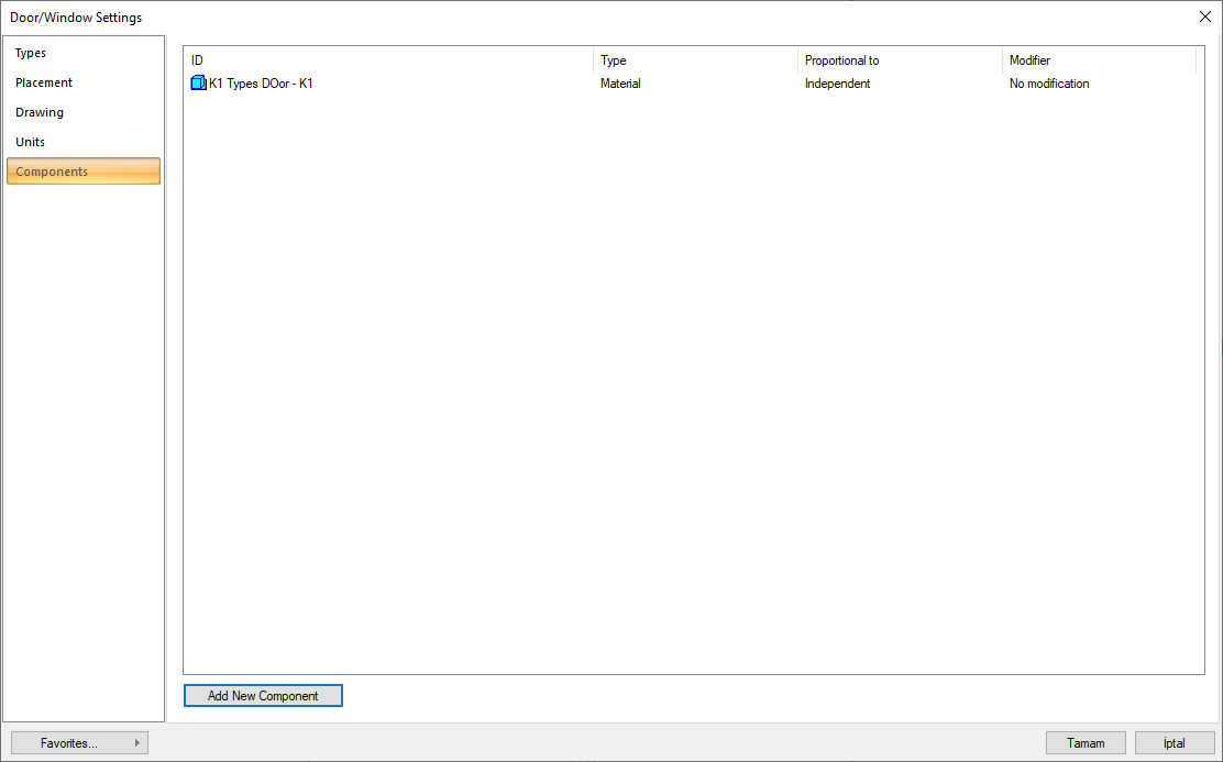
Add building components: Assigns the building materials defined for the detailed building components metering to the wall object.
-
Click the Add Building Component button.
-
The Component Selection dialog will open.
-
In this dialog, click the folder related to the material from the list on the left. Choose the material you want to use.
-
Set the parameters on the right.
-
Click the OK button. The "Component Selection" dialog will be closed. A summary line of the material will appear in the Building Components tab. More than one material assignment can be made to an object.
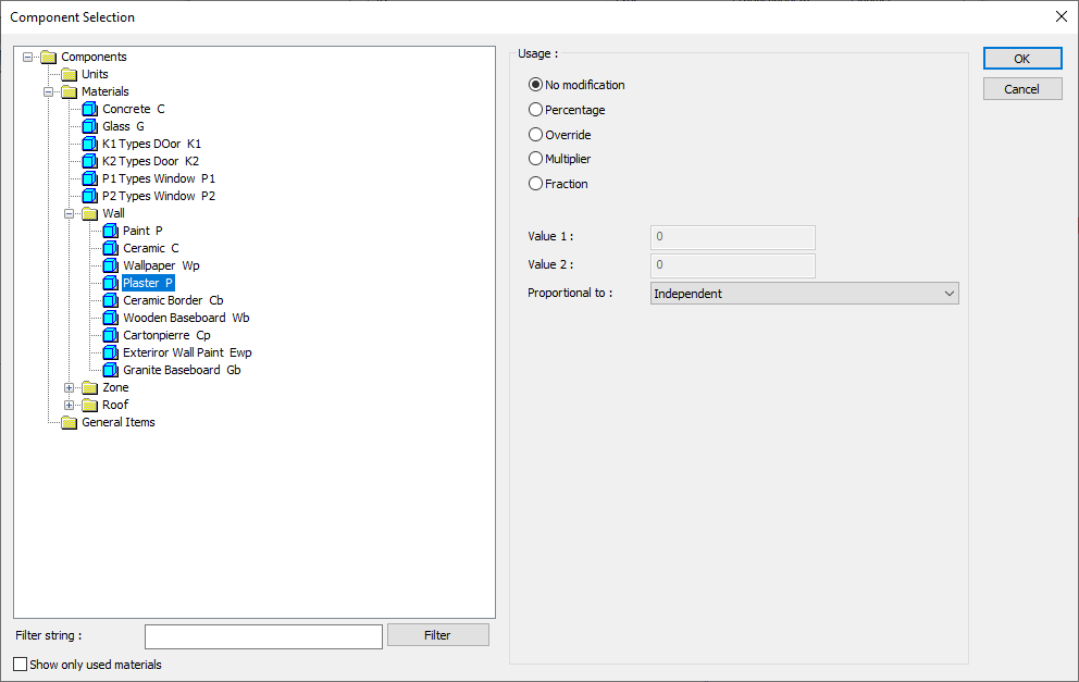
In the usage section
No modification: The amount of material to be assigned for the object in question is marked when it is desired to be used in the size that was previously specified in the material definition.
Percentage: This line is marked when it is desired to be used with the percentage of the amount previously determined in the material definition, as much as the value entered in the "Value 1" line in the same dialog. For example, if the material quantity is 70, if the line “Value 1” says 40, it means the material amount will be used up to 40 * 70%.
Override: This line is marked so that the quantity entered in the “Value 1” line in the same dialog will be used instead of the quantity previously determined in the material definition.
Multiplier: This line is marked in order to use the value found at the end of the multiplication of the value entered in the "Value 1" line in the same dialog with the amount previously determined in the material definition.
Fraction: This line is marked so that the amount determined in the material definition before will be used as the fraction value created by the values entered in the "Value 1" and "Value 2" lines in the same dialog. "Value 1" is the denominator "Value 2" is the denominator.
Proportional to: It is determined to what scale-area, circumference, length etc.-, region-side area, top, edge etc.- the material will be proportioned to. The content of the proportional list box is automatically determined according to the object and the size of the material. For example, a different list will be created if an operation is made for the column, a different list will be created for the library, a different list for the volume, and a different list for the field.
Following are the lines that appear in the proportion list according to the door/window object and material size.
|
Door/window |
||
|
Measure |
Listed |
Explanation |
|
Constant |
Independent |
It means that the length measure found while defining the material will be used exactly as the length value. |
|
Length |
Independent |
It means that the length measure found while defining the material will be used exactly as the length value. |
|
Width |
It means that the length of the material will be found by multiplying the length measurement found when defining the material and the width of the door / window. |
|
|
Thickness |
It means that the length of the material will be found by multiplying the length measurement found when defining the material and the thickness of the door / window. |
|
|
Area |
Independent |
It means that the area measure found while defining the material will be used exactly as the amount. |
|
Area |
It means that the area measure found when defining the material will be multiplied by the area of the door / window. |
|
|
Volume |
Independent |
The volume measure found when defining the material will be used exactly as the volume of the material. |
|
Count |
Independent |
The number measure found while defining the material will be used exactly as the material number. |
|
|
Count |
The number measure found while defining the material will be used exactly as the material number. |
|
|
Openings count |
When defining the material, the number measure is multiplied by the opening number (the ideCAD automatically finds it according to the structure of the door / window) and it means that the opening count will be found. |
Next Topic